

DEMO - 1969 Colorized Mustang Wiring and Vacuum Diagrams
DEMO - 1969 Colorized Mustang Wiring and Vacuum Diagrams
DEMO - 1969 Colorized Mustang Wiring and Vacuum Diagrams

Create successful ePaper yourself
Turn your PDF publications into a flip-book with our unique Google optimized e-Paper software.
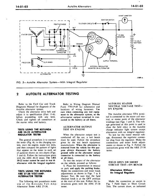
14-0 1-03 Autolite Alternators 1 4-0 1-03SHUNT AMMETER-12-VOLTBATTERYL -------------JALTERNATOR-MOUNTED ONJl409.AFIG. 3-Autolite Alternator System-With Integral Regulator2 AUTOLITE ALTERNATOR TESTINGRefer to the Ford Car <strong>and</strong> TruckDiagnosis Manual for diagnosis of theAutolite alternator system.Check the alternator drive belt <strong>and</strong>adjust it to specification (Part 13-6),before proceeding with any tests.Check <strong>and</strong> tighten all connectors atthe starter relay <strong>and</strong> battery.TESTS USING THE ROTUNDAARE 20-22 ALT ERNATORREGULATOR TESTERThe general procedure, is to connectthe tester (Fig. 4), to the charging system,start the engine, make two tests,<strong>and</strong> then comparethe pattern of lightsthat appear on the tester to each setof patterns shown on two charts (Figs.5 <strong>and</strong> 6). Follow the instructions givenwith the ARE 20-22 tester. The -ARE20-22 tester cannot be used to test thalternator with. the integral regulator.TESTS USING THE ROTUNDAARE 27-38 VOLT-AMP-ALTERNATOR TESTERTne following test procedures makeuse of the Rotunda Volt Amp-Alternator Tester ARE 27-38.Refer to <strong>Wiring</strong> Diagram ManualForm 7795-P-69 for schematics <strong>and</strong>locations of wiring harnesses. Usecare when connecting any test equipmentto the alternator system, as thealternator output terminal is connectedto the' battery at all times.ALTERNATOR OUTPUTTEST ON ENGINEWhen the alternator output test isconducted off the car, a test benchmust be used. Follow the proceduregiven by the test bench equipmentmanufacturer. When the alternator isremoved from the vehicle for this purposealways disconnect the batteryground cable as the alternator outputconnector is connected to the batteryat all times.To tesi the output of the alternatoron the vehicle, proceed as follows:1. Place the transmission in neutralor park <strong>and</strong> apply the parking brake.Make the connections <strong>and</strong> tester knobadjustments as shown in Figs. 7 or 8Output Test. Be -sure that the field'rheostat knob is at the OFF positionat the start of this test. Follow the instructionsgiven with the ARE 27-38tester.A UTOLITE STATORNEUTRAL VOLTAGE TEST-ON ENGINEThe .Autolite alternator STA terminalis connected to the stator coil neutral;or center point of the alternatorwindings (see Figs. I <strong>and</strong> 2). The voltagegenerated at this point is used toclose the field relay in the Autolitecharge indicator light system exceptalternators with an integral regulator.To test for the stator neutral voltage,disconnect the regulator connectorplug from theregulator. Make theconnections <strong>and</strong> tester knob adjustmentsas shown in Fig. 9. Follow theinstructions given with the ARE 27-38tester.FIELD OPEN OR SHORTCIRCUIT TEST-ON BENCHAlternators WithoutAn Integral RegulatorMake the connection as mown inFig. 7 Field Open or Short CircuitTest. The current draw, as indicated


