Granular Filter Design for Scour Protection at Offshore Structures
Granular Filter Design for Scour Protection at Offshore Structures
Granular Filter Design for Scour Protection at Offshore Structures
- No tags were found...

You also want an ePaper? Increase the reach of your titles
YUMPU automatically turns print PDFs into web optimized ePapers that Google loves.
For more in<strong>for</strong>m<strong>at</strong>ion contact:James Bernegger, DirectorCorpor<strong>at</strong>e Marketing and Communic<strong>at</strong>ions863-644-2431 x112E-mail: news@sun-n-fun.orgFOR IMMEDIATE RELEASESUN `N FUN RECOGNIZES 20 TH ANNIVERSARY OFOPERATION DESERT STORMSUN ’n FUN CAMPUS, LAKELAND, FL. – (February 21, 2011) – The 20 th anniversary of “Oper<strong>at</strong>ionDesert Storm” will be recognized during the 37 th annual SUN ’n FUN Intern<strong>at</strong>ional Fly-In and Expo.This year’s Fly-In will take place March 29 – April 3 <strong>at</strong> Lakeland Linder Regional Airport in Lakeland,Fla.United St<strong>at</strong>es Army Brigadier General Rhonda Cornum and her husband, United St<strong>at</strong>es AirForce Brig. Gen. Kory Cornum, both served in Desert Storm and will provide their unique perspectiveson the military str<strong>at</strong>egies and their successful conclusion during the First Persian Gulf War.“It’s hard to believe th<strong>at</strong> it’s been 20 years since Desert Storm,” said SUN ’n FUN President andConvention Chairman John Burton. “We are honored to have these two high-ranking military veteranswho so honorably served in Desert Storm and who remain in service to our country to this day. Theirprogram will be one th<strong>at</strong> SUN ’n FUN participants and guests will be talking about <strong>for</strong> a long time.”The two Generals (who are also medical doctors) will offer their insights and experiencesrel<strong>at</strong>ing to the conflict from the Army (Rhonda) and Air Force (Kory) perspectives and provideadditional in<strong>for</strong>m<strong>at</strong>ion on the critical roles played by other branches of the military. Both served inDesert Storm: Rhonda as a Flight Surgeon with the Army’s 2/229 Attack Helicopter B<strong>at</strong>talion flyingAH-64 Apaches and UH-60 Blackhawks and Kory as a Flight Surgeon with the Air Force’s 58 th TacticalFighter Squadron flying F-15s.During the last week of February 1991, while per<strong>for</strong>ming a search and rescue mission <strong>for</strong> adowned Air Force F-16 pilot, Rhonda’s Blackhawk helicopter was shot down. Five of the eight-personcrew were killed. The three survivors, including Gen. Cornum, were captured by Iraqi <strong>for</strong>ces and held<strong>for</strong> eight days be<strong>for</strong>e being rep<strong>at</strong>ri<strong>at</strong>ed.- MORE -
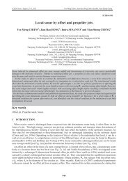
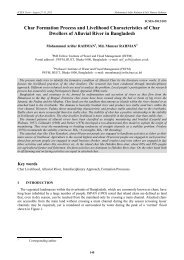
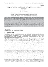
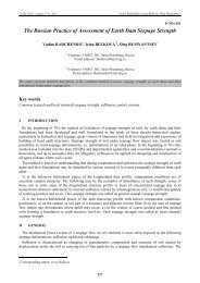
ICSE6 Paris - August 27-31, 2012David Schürenkamp, M<strong>at</strong>thias Bleck and Hocine Oumeraci - Advanced <strong>Filter</strong> <strong>Design</strong>In the following, a scour protection made of a rockarmour with a multi-layer granular filter is exemplarilyconsidered to address the a<strong>for</strong>e mentioned issues. Sucha scour protection has been tested in the ‘Großen Wellenkanal’(GWK, Hannover) as shown in Figure 1(Oumeraci et al., 2007).The failure of marine structures is often due to thefailure of their granular filters as reliable filter design<strong>for</strong>mulae are still lacking (Oumeraci, 1996). There<strong>for</strong>e,a brief critical review of the liter<strong>at</strong>ure of the presentknowledge will be conducted below to show th<strong>at</strong> theknowledge associ<strong>at</strong>ed with the hydro-geotechnicalprocesses involved in the flow-filter-interaction is stillnot sufficient <strong>for</strong> the development of such <strong>for</strong>mulae.Moreover, this review will enable through a combin<strong>at</strong>ionof the existing knowledge and <strong>for</strong>mulae to proposeand critically discuss a tent<strong>at</strong>ive approach <strong>for</strong> the designof granular filters <strong>for</strong> a scour protection around amonopile found<strong>at</strong>ion of offshore wind turbines whichFigure 1: <strong>Scour</strong> protection around a monopile found<strong>at</strong>ion,‘Großer Wellenkanal’ Hannover (Oumeraciet al., 2007)fulfils the a<strong>for</strong>e mentioned requirements with respect to hydraulic stability, constructability and cost effectiveness.Finally some recommend<strong>at</strong>ions <strong>for</strong> further research will be given.IIPRESENT KNOWLEDGE FOR THE DESIGN OF GRANULAR FILTERSII.1Types of flow conditions within a granular filterThe primary function of a granular filter of marine structures is to prevent the underlying soil layers frombeing washed outthrough the pore structurea) Parallel unidirectional flow b) Parallel oscill<strong>at</strong>ory flowof the protectivelayers. In addition,Hsufficiently thickgranular filters can alsosubstantially contributeto dissip<strong>at</strong>e pressureArmour Layer<strong>Filter</strong> Layeru wArmour Layer<strong>Filter</strong> Layer(e.g. pore pressure inthe soil, uplift pressureon the marine structure).Because of thisSubsoilc) Perpendicular unidirectional flow d) Perpendicular oscill<strong>at</strong>ory flowSubsoilsecondary function(particularly in the caseHof high interfacial pressurezgradients), butalso in view of furtherArmour LayerArmour Layeradvantages such as<strong>Filter</strong> Layer<strong>Filter</strong> Layerdurability and interlockingSubsoilSubsoilwith the pro-tective layer, granularfilters are often favouredin comparison Figure 2: Types of flow conditions within a scour protection of a monopile found<strong>at</strong>ionto geotextile filters<strong>for</strong> offshore structures(CEM, 2008).As a result of waves, currents and their combined action near shore and offshore, the sea bed and granularfilters are subject to four basic types of flow conditions, depending on the flow direction rel<strong>at</strong>ive to the interfacesof the different layers (indic<strong>at</strong>ed in red colour in Figure 2 a-d): (i) parallel unidirectional flow, (ii) paralleloscill<strong>at</strong>ory flow, (iii) perpendicular unidirectional flow and (iv) perpendicular oscill<strong>at</strong>ory flow.1028
ICSE6 Paris - August 27-31, 2012David Schürenkamp, M<strong>at</strong>thias Bleck and Hocine Oumeraci - Advanced <strong>Filter</strong> <strong>Design</strong>For parallel flow conditions, the interface between armour and filter layer is more relevant, whereas the interfacebetween filter layer and sea bed is more relevant <strong>for</strong> perpendicular flow conditions. The actual flowconditions may also result from the combin<strong>at</strong>ion of any of these four types of flow conditions (de Graauw etal., 1983). The loading conditions in a marine environment with waves and tides <strong>for</strong> a scour protection aregenerally the result of a combin<strong>at</strong>ion of types a, b and d in Figure 2. Types c in Figure 2 may occur <strong>for</strong> instanceas a result of ship-induced wave.II.2<strong>Filter</strong> design approachThere are three basic concepts <strong>for</strong> the design of granular filters: (i) geometrical filter criteria, (ii) hydraulicfilter criteria and (iii) dynamic filter <strong>for</strong> broadly graded filter (CUR161, 1993; Schiereck, 2001). Differentdesign approaches can be applied: stable filter, semi-stable and dynamically stable filter concepts (CUR161,1993). Depending on the design approach selected, different filter criteria must be fulfilled. These includesamongst others (i) retention criterion to ensure stability against contact erosion and thus prevent leaching offiner fractions through the adjacent layer, (ii) internal stability criterion to prevent suffusion, (iii) permeabilitycriterion to minimise hydraulic pressure gradient through the layer (iv) filter thickness criterion to dampsevere hydrodynamic loading. Further consider<strong>at</strong>ions such as covering sea bottom irregularities, compens<strong>at</strong>ionof differential settlements, construction method and tolerances, exposure during construction, constructionin deeper w<strong>at</strong>er may dict<strong>at</strong>e much thicker filters than required from the hydraulic stability criteria alone(de Graauw et al., 1983; Wörman, 1989). Moreover, stability against segreg<strong>at</strong>ion during construction mayalso be an important issue depending on the w<strong>at</strong>er depth and the construction methods. To reduce segreg<strong>at</strong>iongeometrical criteria are primarily applied. For a filter construction under w<strong>at</strong>er, a narrowly graded andpossibly coarser filter m<strong>at</strong>erial with a uni<strong>for</strong>mity coefficient Cu ≤ 5 is recommended by the BAW (1989).II.3Geometrically closed filterHitherto, geometrical filter criteria based on characteristic grain sizes of the filter layers and adjacent soillayers are mostly applied in engineering practice. Such an approach implicitly requires th<strong>at</strong>, irrespective ofthe hydraulic loading conditions, the filter m<strong>at</strong>erial should have openings (constrictions) sufficiently small toretain the finer particles of the soil m<strong>at</strong>erial likely to migr<strong>at</strong>e from being washing out. If the constrictions aresmaller than the characteristic grain size of the base m<strong>at</strong>erial, the filter is called geometrically closed. However,depending on the function of the filter, its applic<strong>at</strong>ion area and maintenance, the required retention mustnot be total. Generally, the primary aim of a filter is to retain the soil as a whole but not necessarily all particles.The challenge of any filter design is there<strong>for</strong>e to ensure a proper balance between soil retention andpermeability (optimum retention).Particularly when subject to highly turbulent, multidirectional and oscill<strong>at</strong>ory flow, such as filter applic<strong>at</strong>ions<strong>for</strong> coastal and offshore structures, this requirement can only be fulfilled by using a multi-layer filter(generally two or three filter layers between the base m<strong>at</strong>erial and the armour layer). The construction ofsuch filter layers is however associ<strong>at</strong>ed with considerable difficulties, including the risk of drift and segreg<strong>at</strong>ionof the granular m<strong>at</strong>erial during placement, imprecise distribution in thin multi-layers, increasederodibility around the pile structure to be protected and thus erosion of the unprotected filter layers be<strong>for</strong>ecompletion of the cover layer, etc. A further drawback of multi-layer filters in deeper w<strong>at</strong>er is the minimumlayer thickness requirement <strong>for</strong> an adequ<strong>at</strong>e construction (≥ 0.50 m) which together with all difficulties associ<strong>at</strong>edwith their construction would result in excessively high costs (Schürenkamp, 2011).Most of the geometrically closed filter criteria origin<strong>at</strong>e from dam engineering where the filter and the basem<strong>at</strong>erial are subject to non-turbulent and unidirectional flow and generally a total retention is required. Basedon the results of the labor<strong>at</strong>ory experiments of de Graauw et al. (1983) who investig<strong>at</strong>ed system<strong>at</strong>ically thestability of granular filter under both unidirectional and oscill<strong>at</strong>ory flow, Oumeraci (1996) concluded th<strong>at</strong> theapplic<strong>at</strong>ion of these criteria to filters subject to sea waves is questionable.1029
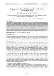
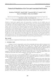
ICSE6 Paris - August 27-31, 2012David Schürenkamp, M<strong>at</strong>thias Bleck and Hocine Oumeraci - Advanced <strong>Filter</strong> <strong>Design</strong>II.4Geometrically open filterII.4.1 GeneralIn contrast to the geometrically closed filter, the hydraulic loading conditions are taken into account in orderto achieve a more economic design. The filter should sufficiently reduce the hydraulic loads <strong>at</strong> the basem<strong>at</strong>erial, so th<strong>at</strong> the base m<strong>at</strong>erial is not moved. Such a filter is called a geometrically open filter. Its applic<strong>at</strong>ionrequires however knowledge of both actual and critical hydraulic loads (critical hydraulic gradient orcritical flow velocity). The critical hydraulic loads causing failure may occur as a result of flow perpendicularor parallel to the interface between the layers of the granular m<strong>at</strong>erial as illustr<strong>at</strong>ed in Figure 3 showingtwo types of failure mechanisms.To assess such failure mechanisms andto properly design the filter, a detailedknowledge of the hydraulic processesinvolved within the filter and the basem<strong>at</strong>erial is needed. The failure andtransport mechanism in both filter andbase m<strong>at</strong>erial will depend on the type anddirection of the internal flow. As alreadyillustr<strong>at</strong>ed in Figure 2 four basic flow conditionsin the porous media may be distinguished.Perpendicular flow directed upwardswill lift the soil particles (liquefaction)while parallel flow will cause shearfailure, but both effects actually occur incombin<strong>at</strong>ion (Zichel & Oumeraci, 2012).II.4.2 Parallel flowIt is generally assumed th<strong>at</strong> mobilizing <strong>for</strong>ces on a single particle of the granular m<strong>at</strong>erial are drag, lift andinertia <strong>for</strong>ces while the resisting <strong>for</strong>ces are provided by gravity, friction and interlocking (Raudkivi, 1982;Hansen, 1985). A particulardifficulty is the determin<strong>at</strong>ionof the flow velocity and shearstress inside the filter andcover layer (see Figure 4).In order to investig<strong>at</strong>e thedamping of the flow inducedby a layer of granular m<strong>at</strong>erial,labor<strong>at</strong>ory experimentswere per<strong>for</strong>med by Booij(1998) <strong>for</strong> uni-directionalflow and by Wenka andKöhler (2007) <strong>for</strong> oscill<strong>at</strong>oryflow conditions. Several casestudies <strong>for</strong> the filter stabilityof different types of bedU (z)u fLiquefactiona) Flow profile b) Shear stress distribution1,5 ∙ D 50unidirectional flow<strong>Filter</strong> layerBase Layeri krit perpendicularscour protection and slope revetments were conducted <strong>for</strong> parallel and unidirectional flow conditions. Manyof the hydraulic filter criteria applied are based on a critical shear stress according to the Shields concept.The approaches proposed by Bakker et al. (1994), Sumer and Fredsøe (2002), Hoffmans et al. (2008) arerel<strong>at</strong>ed to scour protection of a horizontal sand bed under turbulent flow conditions. The only design <strong>for</strong>mulayet available and applicable <strong>for</strong> a scour protection around a cylindrical monopile subject to parallel and unidirectionalflow has been proposed by Wörman (1989) on the basis of hydraulic model tests. A single protectivelayer of rock embedded with the top <strong>at</strong> the bed level without any further layer was investig<strong>at</strong>ed by usingtwo cylinder diameters, five types of rock m<strong>at</strong>erial and three types of sand. The primary function of the protectiverock layer is to achieve a sufficient damping of the hydraulic gradient i within the rock layer, and thusto prevent bed scour. For this purpose, the required rock layer thickness D F depends on the velocity of theD Fτ (z)τ b1,5 ∙ D 50Shear failurei krit parallelFigure 3: Failure mechanisms induced by perpendicular and parallelflow to the filterunidirectional flow<strong>Filter</strong> <strong>Filter</strong> layer layerBase LayerFigure 4: Flow profile and shear stress distribution in a filter (Booij, 1998;Zichel & Oumeraci, 2012)D F1030
ICSE6 Paris - August 27-31, 2012David Schürenkamp, M<strong>at</strong>thias Bleck and Hocine Oumeraci - Advanced <strong>Filter</strong> <strong>Design</strong>pore w<strong>at</strong>er flow, the properties of the pore fluid, the pile diameter as well as on the size and porosity of therock m<strong>at</strong>erial. The primary objective of the analysis of the results was to obtain the rel<strong>at</strong>ionship between thepressure gradient U²/(g · D F ) within the rock layer with thickness D F and the r<strong>at</strong>io (d 85B /d 15F ) of the grain sizeof the base m<strong>at</strong>erial d 85B to th<strong>at</strong> of the rock layer d 15F . U represents the mean velocity of a the undisturbedflow (assumed as fully developed, turbulent boundary layer over the rock layer) and g gravity acceler<strong>at</strong>ion,Such a rel<strong>at</strong>ionship is intended to represent a criterion <strong>for</strong> incipient erosion-transport of the base m<strong>at</strong>erialthrough the rock layer which essentially depends on the undisturbed mean flow velocity U, the thickness D Fof the rock layer and the grain size r<strong>at</strong>io d 15F /d 85B . The obtained rel<strong>at</strong>ionship shows th<strong>at</strong> thickness D F increaseswith increasing r<strong>at</strong>io d 15F /d 85B (given same flow conditions) and with increasing flow velocity U. Moreover,it is shown th<strong>at</strong> <strong>for</strong> extremely high pressure gradients, r<strong>at</strong>io d 85B /d 15F asymptotically approaches the conditionsof geometrically closed filters.Madsen and Grant (1976) have experimentally demonstr<strong>at</strong>ed th<strong>at</strong> the Shields concept <strong>for</strong> incipient motionof granular m<strong>at</strong>erial, initially developed <strong>for</strong> unidirectional flow, can also be used <strong>for</strong> oscill<strong>at</strong>ory near bottomflow induced by sea waves. Similarly, it is assumed th<strong>at</strong> the concept proposed by Wörman (1989) <strong>for</strong> incipienterosion-transport of the base m<strong>at</strong>erial through the rock layer under unidirectional flow can also be applied<strong>for</strong> oscill<strong>at</strong>ory flow in the marine environment. In the following section, the additional flow component perpendicularto the interface between the protective coarser layer and base m<strong>at</strong>erial is considered.II.4.3 Perpendicular flowAs shown in Figures 2c & 2d, both unidirectional and oscill<strong>at</strong>ory flow perpendicular to the interface betweenfilter and base m<strong>at</strong>erial may principally occur. Actually, however, <strong>for</strong> a bed protection subject to seawaves perpendicular oscill<strong>at</strong>ory flow represent the most relevant case as compared to the perpendicular unidirectionalflow. According to the results of de Graauw et al. (1983), a smaller grain size r<strong>at</strong>io of the granularfilter and base m<strong>at</strong>erial will be required <strong>for</strong> oscill<strong>at</strong>ory flow than <strong>for</strong> unidirectional flow. This is particularlydue to stabilizing mechanism such as “arching effect” which may occur and sustained <strong>for</strong> unidirectional flowbut not <strong>for</strong> oscill<strong>at</strong>ory flow. This effect is illustr<strong>at</strong>ed in Figure 5a <strong>for</strong> a unidirectional flow where the <strong>for</strong>m<strong>at</strong>ionof an arch prevents the finer particles of the base m<strong>at</strong>erial from passing through the filter. Under oscill<strong>at</strong>oryflow conditions (Figure 5b), a smaller grain size r<strong>at</strong>io of the filter and base m<strong>at</strong>erial is required to ensurea) Arching b) Geometrically closed<strong>Filter</strong>stability. Moreover, theload exerted by the weightof the filter on the basem<strong>at</strong>erial is also important<strong>for</strong> stability. As illustr<strong>at</strong>edin Figure 5c, the unloadedarea may be subject tolocal soil liquefactionunder high pressure gradients.The processes illustr<strong>at</strong>edin Figure 5 highlightthe relevance of the oscill<strong>at</strong>oryflow in normal direction<strong>for</strong> stability analysis.Its improper consider<strong>at</strong>ionmay result in failure and thus in unsafe filter design. There the flow components in both parallel andorthogonal direction must be properly considered. The still existing knowledge gaps rel<strong>at</strong>ed to this issue andto the processes in Figure 4 may explain why process-based generic filter design <strong>for</strong>mulae are still lacking.The most urgent tasks are there<strong>for</strong>e to determine: (i) reliable prediction <strong>for</strong>mulae <strong>for</strong> the actual hydraulicgradients in the different layers, (ii) the effect of the thickness and weight of the filter and cover layers on thestability of the base m<strong>at</strong>erial and (iii) the development of pore pressure within the base m<strong>at</strong>erial and its explicitconsider<strong>at</strong>ion in the final stability <strong>for</strong>mulae <strong>for</strong> the design of filter and cover layers.<strong>Filter</strong>superimposedloadBase Base Baseunidirectional flowoscill<strong>at</strong>ory flowc) Local liquefaction<strong>Filter</strong>non-loadzoneloadedzoneFigure 5: Arching effect and further processes (modified from de Graauw et al.(1983); Zichel and Oumeraci (2012))IIISUGGESTION OF A “HYBRID” FILTER DESIGN APPROACHAt present, geometrically based criteria are generally favoured due to the uncertainties associ<strong>at</strong>ed with theknowledge particularly rel<strong>at</strong>ed to the oscill<strong>at</strong>ory flow conditions in orthogonal direction. Based on theknowledge readily available, the most reasonable altern<strong>at</strong>ive <strong>for</strong> filter design seems to be a proper combin<strong>at</strong>ionof geometrically and hydraulically based filter criteria. For oscill<strong>at</strong>ory flow in parallel direction a filter1031
ICSE6 Paris - August 27-31, 2012David Schürenkamp, M<strong>at</strong>thias Bleck and Hocine Oumeraci - Advanced <strong>Filter</strong> <strong>Design</strong>design based on the incipient motion of granular m<strong>at</strong>erial according to the Shields concept is theoreticallywell-founded, but the empirical rel<strong>at</strong>ion derived by Wörman (1989) using a similar approach to assess incipienterosion-transport offers substantially more advantages:Implicit account of hydraulic conditions, so th<strong>at</strong> only m<strong>at</strong>erial parameters of the basis and filter arerequired as inputsExplicit consider<strong>at</strong>ion of the thickness of the cover and filter layers which damps the hydraulic loadsand thus strongly affects the stability of the filter and the base m<strong>at</strong>erial Implicit account of the turbulent flow and vortex structure (e.g. horse shoe vortex) around the pilestructure.A combin<strong>at</strong>ion of geometrically and hydraulically based filter criteria is proposed, in which the stability <strong>at</strong>the interface between <strong>Filter</strong> and base m<strong>at</strong>erial can be achieved through geometrical filter criteria while th<strong>at</strong> <strong>at</strong>the interface between cover and filter layer through hydraulic filter criteria. This “hybrid filter design approach”may however result in a progressive erosion of the base m<strong>at</strong>erial under very extreme hydraulic conditionsif the commonly applied geometrical filter criteria are used. This can be slowed down by using improvedcriteria; otherwise periodic monitoring and maintenance will be required. Further uncertainties willarise if the actual conditions significantly differ from those tested by Wörman (1989). For instance, the embeddedcover layer with the top <strong>at</strong> the sea bed level which was tested offers a substantial advantage comparedto non-embedded scour protections (e.g. Figure 1) as the flow in both horizontal and vertical directionsis significantly reduced. An example applic<strong>at</strong>ion of the suggested “hybrid” approach will be given <strong>for</strong> illustr<strong>at</strong>ionin the next section.IVEXAMPLE APPLICATION OF THE SUGGESTED APPROACHThe scour protection of the seabed around a slender monopile asshown in Figure 6 is considered.The armour layer has been designedaccording to the commonly usedhydraulic stability <strong>for</strong>mulae. As aresult an armour with a mean stonediameter d 50D = 0,42 m, a densityρ s,D = 2900 kg/m³ and a thicknessD D = 0,90 m is obtained (seeSchürenkamp, 2011). For the exampleapplic<strong>at</strong>ion, this armour willthere<strong>for</strong>e be assumed as given in afirst step. Further given input conditionsare summarized in Table 1.hDLH Su cArmour Layeru w<strong>Filter</strong> LayerSubsoilFigure 6: <strong>Scour</strong> <strong>Protection</strong> <strong>for</strong> Monopile Found<strong>at</strong>ion (Sketch)Description Symbol Unit Valuew<strong>at</strong>er depth h m 20,0wave height H s m 15,0dry densitiy ρ W kg/m³ 1025stone diameter d 15D m 0,33stone diameter d 50D m 0,42stone diameter d 85D m 0,50porosity of armour layer n D - 0,40thickness of armour layer D D m 0,90dry density of armour m<strong>at</strong>erial ρ s,D kg/m³ 2900dry density of filter m<strong>at</strong>erial ρ s,F kg/m³ 2650Table 1: Input conditions <strong>for</strong> the example applic<strong>at</strong>ion1032
ICSE6 Paris - August 27-31, 2012David Schürenkamp, M<strong>at</strong>thias Bleck and Hocine Oumeraci - Advanced <strong>Filter</strong> <strong>Design</strong>First step: Applying the geometrical filter criterion according to CEM (2008) yields:d15F 4to5·d85B(1)With a grain size of the base m<strong>at</strong>erial d 85B = 0,35 mm (sand), typical <strong>for</strong> the sea bed m<strong>at</strong>erial in the NorthSea, the required grain size of the filter m<strong>at</strong>erial is obtained from equ<strong>at</strong>ion 1: d 15F = 1,40 mm to 1,75 mm. Inthis example d 15F = 1,75 mm is selected with a uni<strong>for</strong>mity coefficient Cu = 5 to reduce segreg<strong>at</strong>ion effectsand a filter layer thickness D F = 0,50 m (see BAW, 1989). The grading of the armour and filter layer (simplifiedrepresent<strong>at</strong>ion) and th<strong>at</strong> of the base m<strong>at</strong>erial are given in Figure 6, resulting in d 85F = 17 mm <strong>for</strong> the filterm<strong>at</strong>erial.Second step: The thickness of the armour layer is now recalcul<strong>at</strong>ed as a function of the properties of bothfilter m<strong>at</strong>erial (d 85F and rel<strong>at</strong>ive density of rock ρ s,F / ρ w to th<strong>at</strong> of w<strong>at</strong>er) and armour m<strong>at</strong>erial (d 15D, d 85D andrel<strong>at</strong>ive density ρ s,D / ρ w ) according to the <strong>for</strong>mula derived by Wörman (1989): sD,/ w1 nDd85D·d15DDD 0,16·· ·(2) 1sF ,/ w1 nDd85FConsidering (ρ s,D = 2900 kg/m³, ρ s,F = 2650 kg/m³ and ρ w = 1025 kg/m³), a layer thickness of the armourlayer D D = 1.2 m (instead of 0.9 m) will be required.Silt Sand Gravelfine medium coarse fine medium coarse fine medium coarseCobblesBouldersd 85B = 0,35 mmd 85F = 17 mmMass distribution in %d 15F = 5 · d 85Bd 15F = 1,75 mmSieve sizeGrain diameter in mmFigure 7: Grading of base, filter and armour m<strong>at</strong>erialThird step: For considering the accuracy of underw<strong>at</strong>er placement in offshore environment a minimumthickness of the filter layer should be met. The thickness of the filter layer D F can be chosen by the commend<strong>at</strong>ionof CEM (2008) with D F ≥ 0.50 m.Among others the stability against erosion of the uncovered filter layer during the different constructionphases should be analysed and a monitoring and maintenance programme should be elabor<strong>at</strong>ed.VCONCLUSIONS AND RECOMMENDATIONS FOR FUTURE RESEARCHA comprehensive review of the available filter criteria was per<strong>for</strong>med and those particularly suitable <strong>for</strong>scour protection of offshore structures such as monopiles were compar<strong>at</strong>ively analysed (see also details inSchürenkamp, 2011). Particularly critical is the contact erosion due to the upwards directed oscill<strong>at</strong>ory flowwhich is not or not properly taken into account in the available design <strong>for</strong>mulae. The same is valid <strong>for</strong> thecombined effect of both oscill<strong>at</strong>ory flow (waves) and unidirectional flow. Solely based on the present knowledgeand the available experience it is hardly possible to reliably design and properly construct a granularfilter <strong>for</strong> a scour protection of offshore structures such as monopiles. Since considerable research and timewill be required to achieve this goal, a “hybrid” design approach is tent<strong>at</strong>ively proposed and an example applic<strong>at</strong>ionis provided <strong>for</strong> illustr<strong>at</strong>ion. The “hybrid” approach <strong>at</strong>tempts to combine geometrical filter criteria todetermine such as the criterion recommended by CEM (2008) and hydraulically based criteria such as thosewhich are summarized by the <strong>for</strong>mula by Wörman (1989). Applic<strong>at</strong>ion of the <strong>for</strong>mer allows to design the1033
ICSE6 Paris - August 27-31, 2012David Schürenkamp, M<strong>at</strong>thias Bleck and Hocine Oumeraci - Advanced <strong>Filter</strong> <strong>Design</strong>filter according to the base m<strong>at</strong>erial while the applic<strong>at</strong>ion of the l<strong>at</strong>er allows to adjust the thickness of thecover layer according to the properties of the filter and cover layer.One of the gre<strong>at</strong>est difficulties <strong>for</strong> the development of design <strong>for</strong>mulae is the consider<strong>at</strong>ion of the oscill<strong>at</strong>oryflow in orthogonal direction. Further important issues which urgently require further research is associ<strong>at</strong>edwith the applic<strong>at</strong>ion of broadly graded m<strong>at</strong>erial, including the development of reliable <strong>for</strong>mulae <strong>for</strong> thedynamic stability (semi-stable filters), segreg<strong>at</strong>ion behaviour in large w<strong>at</strong>er depths (fall pipes), etc.Both basic and applied research are needed to enhance the process understanding, and based on this improvedunderstanding to develop design <strong>for</strong>mulae and guidance <strong>for</strong> the engineering practice. Candid<strong>at</strong>e topicsare <strong>for</strong> instance: Flow velocity and shear stress distribution in both filter and armour layer. Pore pressure distribution in the base m<strong>at</strong>erial (hydraulic gradients) Incipient motion/transport of granular m<strong>at</strong>erial under combined waves and currents <strong>for</strong> different filterand cover layer configur<strong>at</strong>ions, including internal erosion Dynamic design concept/<strong>for</strong>mulae <strong>for</strong> semi-stable filtersVIREFERENCESBakker, K.J.;Verheij, H.J.; de Groot, M.B. (1994): <strong>Design</strong> Rel<strong>at</strong>ionsship <strong>for</strong> <strong>Filter</strong>s in Bed <strong>Protection</strong>.Journal of Hydraulic Engineering, Vol. 120.BAW (1989): Merkbl<strong>at</strong>t: Anwendung von Kornfiltern an Wasserstraßen (MAK). Karlsruhe: Bundesanstaltfür Wasserbau.Booij, R. (1998): Erosie onder en geometrisch open filter. TU Delft, Hydraulic Engineering, Report 1998-2,Delft, 25 S.CEM (2008): Coastal Engineering Manual. United St<strong>at</strong>es, A. and Knovel, eds., U.S. Army Corps ofEngineers, [Washington, D.C], Online-Ressource.CUR161 (1993): <strong>Filter</strong>s in de w<strong>at</strong>erbouw. Rapport / CUR 161, Civieltechnisch Centrum Uitvoering Researchen Regelgeving, CUR, Gouda, 212 S.de Graauw, A.;van der Meulen, T.; van der Does de Bye, M. (1983): <strong>Design</strong> criteria <strong>for</strong> granular filters.Delft: Delft Hydraulics, 25 Bl.Hansen, U.A. (1985): Wasserbausteine im Deckwerksbau - Bemessung und Konstruktion. Heide i. Holstein:Westholsteinische Verlagsanstalt Boyens & Co.Hoffmans, G.;Den Adel, H.; Verheij, H. (2008): Horizontal <strong>Granular</strong> <strong>Filter</strong>s. 4rd Intern.Conference on <strong>Scour</strong>and Erosion ICSE-4, C-16, Tokyo, Japan, 480-485.Madsen, O.S.; Grant, W.D. (1976): Sediment transport in the coastal environment. Research Report.Department of Civil Engineering, School of Engineering, MIT, Cambridge, MA, USA, 105 p.Oumeraci, H. (1996): <strong>Filter</strong>s in coastal structures. Proceedings of 2nd Intern<strong>at</strong>ional Conference onGeofilters, Geofilters '96, Montreal, Canada, pp. 337-347.Oumeraci, H.;Grüne, J.;Sparboom, H.;Schmidt- Koppenhagen, R.; Wang, Z. (2007): Investig<strong>at</strong>ions on scourand scour protection <strong>for</strong> monopile found<strong>at</strong>ion of wind offshore turbines. Forschungszentrum Küste(FZK), Hannover, pp. 79.Raudkivi, A.J. (1982): Grundlagen des Sedimenttransports. Berlin [u.a.]: Springer, 255 S.Schiereck, G.J. (2001): Introduction to bed, bank and shore protection. Delft, The Netherlands: DelftUniversity Press, 397 p.Schürenkamp, D. (2011): <strong>Filter</strong>aufbauten an Sohlsicherungen von <strong>Offshore</strong>-Windkraftanlagen. Leichtweiß-Institut für Wasserbau, Fachbereich Bauingenieurwesen, Technische Universität Braunschweig,Braunschweig, Germany, 183 S., M-1/2011.Sumer, B.M.; Fredsøe, J. (2002): The mechanics of scour in the marine environment. Advanced series onocean engineering, River Edge, NJ, USA: World Scientific Publishing, 552 p.Wenka, T.; Köhler, H.-J. (2007): Simultane Druck- und 3D-Geschwindigkeitsmessungen im Porenraumeiner Kiessohle. Bundesanstalt für Wasserbau, Mitteilungsbl<strong>at</strong>t Nr. 90, Juli 2007, WasserbaulichesVersuchswesen, Karlsruhe, 119-136.Wörman, A. (1989): Riprap <strong>Protection</strong> without <strong>Filter</strong> Layers. Journal of Hydraulic Engineering, Vol. 115.Zichel, B.; Oumeraci, H. (2012): Kornfilter mariner Bauwerke. Berichte Leichtweiß-Institut für Wasserbau,Technische Universität Braunschweig, Nr. 1014, Braunschweig, Germany, 120.1034