circuit breakers, switch-disconnectors
circuit breakers, switch-disconnectors
circuit breakers, switch-disconnectors

You also want an ePaper? Increase the reach of your titles
YUMPU automatically turns print PDFs into web optimized ePapers that Google loves.
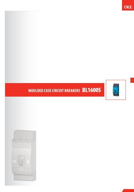
HMOULDED CASE CIRCUIT BREAKERS BL1600SH
BL1600SCOMMERCIAL INFORMATION3PSwitching units, withdrawable device, plug-in device ........................................................................................H4Overcurrent releases ...............................................................................................................................................................H5Signalling units ..........................................................................................................................................................................H5Connecting sets ..........................................................................................................................................................................H6Switches .........................................................................................................................................................................................H8Shunt trips ....................................................................................................................................................................................H8Undervoltage releases ...........................................................................................................................................................H8Hand drives ...................................................................................................................................................................................H9Mechanical interlocking .......................................................................................................................................................H9Motor drives .................................................................................................................................................................................H9Accessories ..................................................................................................................................................................................H10Purchase order example .....................................................................................................................................................H11Custom assembly of <strong>circuit</strong> <strong>breakers</strong>..................................................................................................H11TECHNICAL INFORMATIONCircuit <strong>breakers</strong>, <strong>switch</strong>-<strong>disconnectors</strong>- specifications ......................................................................................................................................H12- wiring diagram ...................................................................................................................................H13- connecting, installation .......................................................................................................................H14- deionization space ...............................................................................................................................H17- dimensions ..........................................................................................................................................H18Withdrawable device - description, specifications, wiring diagram .........................................................................................H30Overcurrent releasesGeneral information .....................................................................................................................H32DTV3 - distribution- description, specifications, tripping characteristics ...........................................................................H34MTV8 - motor- description, specifications, tripping characteristics ...........................................................................H35U001 - universal- description, specifications, tripping characteristics ...........................................................................H37Signalling unitsConnecting setsSwitchesShunt trips- description, specifications, wiring diagram .........................................................................................H40- specifications ......................................................................................................................................H14- specifications, wiring diagram ............................................................................................................H41- specifications, wiring diagram ............................................................................................................H42Undervoltage releases- specifications, wiring diagram ............................................................................................................H43Hand drives- description, specifications ...................................................................................................................H44Mechanical interlocking- description, specifications, dimensions ...............................................................................................H45Motor drives- description, specifications, wiring diagram .........................................................................................H47H2
BL1600SSUMMARY OF MODELS AND ACCESSORIESCONNECTING SETSClamp type terminals Clamp type terminals Block type terminals Block type terminals Block type terminals Rear connection Front connection Rear connection3PCS-BL-W010CS-BL-W011 CS-BL-B002 CS-BL-B003 CS-BL-B004CS-BL-A021 CS-BL-A010 CS-BL-A020HAND DRIVESRP-BL-CK10RP-BL-CP…SWITCHING UNITBL1600SE305SWITCHING UNIT -WITHDRAWABLE DESIGNBL1600SE320WITHDRAWABLE DEVICEZV-BL-1600-300RP-BL-CH10RP-BL-CN…Mechanical interlockingRL-BL-CB10Mechanicalinterlockingby BowdenMB-BL-....MOTOR DRIVESMP-BL-X…SWITCHES PS-BL-…Position signallingSO-BL-0010SHUNT TRIPOVERCURRENT RELEASESSWITCH-DISCONNECTOR UNITSIGNALLING UNITSSV-BL-X…UNDERVOLTAGE RELEASESP-BL-X…SE-BL-....-DTV3SE-BL-....-MTV8SE-BL-1600-V001SB-BL-0002SE-BL-....-U001ACCESSORIESLocking-type leverSealing insetExtension cableTerminal coverTerminal coverOD-BL-UP01OD-BL-VP01OD-BL-KA01OD-BL-KS01OD-BL-KS04Insulating barriersInsulating barriersInsulating grommetsMounting boltsOD-BL-KS02OD-BL-KS08OD-BL-KS03OD-BL-MS02H3
BL1600S - Commercial informationOVERCURRENT RELEASESDTV3 - characteristic D - distribution protecting lines and transformersI n[A] Type Product code Description Weight [kg] Packing [pc]630 SE-BL-0630-DTV3 20070 Regulation I r= 250 ÷ 630 A 0.5 11000 SE-BL-1000-DTV3 20080 Regulation I r= 400 ÷ 1000 A 0.5 11250 SE-BL-1250-DTV3 19388 Regulation I r= 500 ÷ 1250 A 0.5 11600 SE-BL-1600-DTV3 20090 Regulation I r= 630 ÷ 1600 A 0.5 1- TECHNICAL INFORMATION, see page H343PMTV8 - characteristic M - motor direct protection for motors and generators suitable also for protecting lines and transformersI n[A] Type Product code Description Weight [kg] Packing [pc]630 SE-BL-0630-MTV8 20071 Regulation I r= 250 ÷ 630 A 0.5 11000 SE-BL-1000-MTV8 20081 Regulation I r= 400 ÷ 1000 A 0.5 11250 SE-BL-1250-MTV8 19389 Regulation I r= 500 ÷ 1250 A 0.5 11600 SE-BL-1600-MTV8 20091 Regulation I r= 630 ÷ 1600 A 0.5 1- TECHNICAL INFORMATION, see page H35U001 - characteristic U - universal protecting complicated loads or those not specified in advanceI n[A] Type Product code Description Weight [kg] Packing [pc]630 SE-BL-0630-U001 20523 Regulation I r= 250 ÷ 630 A 0.59 11000 SE-BL-1000-U001 20364 Regulation I r= 400 ÷ 1000 A 0.59 11250 SE-BL-1250-U001 20521 Regulation I r= 500 ÷ 1250 A 0.59 11600 SE-BL-1600-U001 20363 Regulation I r= 630 ÷ 1600 A 0.59 1- TECHNICAL INFORMATION, see page H37SWITCH-DISCONNECTOR UNIT3PI e[A] Type Product code Name Weight [kg] Packing [pc]1600 SE-BL-1600-V001 20400 Switch-disconnector unit 0.4 1- TECHNICAL INFORMATION, see page H12SIGNALLING UNIT3PType Product code Description Weight [kg] Packing [pc]SB-BL-0002 13765 - for overcurrent releasesDTV3, DTV8 and U001- TECHNICAL INFORMATION, see page H400.67 1H5
BL1000S, BL1600S - Commercial informationCONNECTING SETS3PType Product code Description S [mm 2 ] Connection Weight [kg] Packing [set] 1)CS-BL-B002 20116 Block type terminal- for 2 cables- TECHNICAL INFORMATION, see page H15150 ÷ 300 Cu/Al cables 1.00 1CS-BL-B003 20117 Block type terminal- for 3 cables- TECHNICAL INFORMATION, see page H15150 ÷ 300 Cu/Al cables 2.00 1CS-BL-B004 20118 Block type terminal- for 4 cables- TECHNICAL INFORMATION, see page H15150 ÷ 300 Cu/Al cables 1.80 11)- One set provides for connecting one side of the <strong>circuit</strong> breaker (set includes three terminals with necessary coupling elements.)H7
BL1000S, BL1600S - Commercial informationAUXILIARY SWITCHES3PType Product code Operational voltage Contacts Weight [kg] Packing [pc]PS-BL-2200 20510 60 ÷ 500 V a.c./60 ÷ 240 V d.c. 0.041 1PS-BL-2200-Au 12808 5 ÷ 60 V a.c./d.c. 0.041 1- TECHNICAL INFORMATION, see page H41SHUNT TRIPS3PUNDERVOLTAGE RELEASESType Product code Operational voltage Weight [kg] Packing [pc]SV-BL-X024 16162 24 V a.c/d.c. 0.22 1SV-BL-X048 16161 48 V a.c/d.c. 0.22 1SV-BL-X110 16160 110 V a.c/d.c. 0.22 1SV-BL-X230 16159 230 V a.c./220 V d.c. 0.22 1SV-BL-X400 16158 400 V a.c. 0.22 1SV-BL-X500 16157 500 V a.c. 0.22 1- TECHNICAL INFORMATION, see page H423PType Product code Operational voltage Weight [kg] Packing [pc]SP-BL-X024 16168 24 V a.c/d.c. 0.22 1SP-BL-X048 16167 48 V a.c/d.c. 0.22 1SP-BL-X110 16166 110 V a.c/d.c. 0.22 1SP-BL-X230 16165 230 V a.c./220 V d.c. 0.22 1SP-BL-X400 16164 400 V a.c. 0.22 1SP-BL-X500 16163 500 V a.c. 0.22 1- TECHNICAL INFORMATION, see page H43H8
BL1000S, BL1600S - Commercial informationHAND DRIVES3PType Product code Name - description Weight [kg] Packing [pc]RP-BL-CK10 20850 Hand drive unit - lockable 0.23 1- TECHNICAL INFORMATION, see page H44Hand drive unit is necessary to be completed: for controlling using the <strong>switch</strong> unit - with the black hand drive lever RP-BL-CP for controlling through the <strong>switch</strong>gear door - with the extension shaft RP-BL-CH10- with the hand drive bearing RRP-BL-CN..- with the hand drive lever RP-BL-CP..Up to 5 hand drive units can be ordered with the same lock.RP-BL-CP10 20865 Hand drive lever - black - lockable 0.261 1RP-BL-CP11 20867 Hand drive lever - red - lockable 0.261 1- TECHNICAL INFORMATION, see page H44RP-BL-CN10 20870 Hand drive bearing - protection IP44 1.1 1- TECHNICAL INFORMATION, see page H44RP-BL-CN20 19103 Hand drive bearing - protection IP66 1.1 1- TECHNICAL INFORMATION, see page H44RP-BL-CH10 20875 Extension shaft - length 365 mm 0.352 1- TECHNICAL INFORMATION, see page H44MECHANICAL INTERLOCKINGMOTOR DRIVESTo the hand driveType Product code Description Weight [kg] Packing [pc]RP-BL-CB10 20880 For <strong>circuit</strong> breaker/<strong>switch</strong>-disconnector in fixed design 0.12 1- TECHNICAL INFORMATION, see page H45- Both <strong>circuit</strong> <strong>breakers</strong> must be equipped with hand drive (at least with a hand drive unit and hand drive lever).By BowdenType Product code Description Weight [kg] Packing [pc]MB-BL-PP07 19807 For <strong>circuit</strong> breaker/<strong>switch</strong>-disconnector in fixed design 0.4 1MB-BL-PV08 1) 20529 For one fixed and one withdrawable <strong>circuit</strong> breaker/<strong>switch</strong>-disconnector 0.4 1MB-BL-VV06 1) 20528 For <strong>circuit</strong> breaker/<strong>switch</strong>-disconnector in withdrawable design 0.4 1- TECHNICAL INFORMATION, see page H451)- Available for sale from second quarter of 2006.3P3PType Product code Name - description Operational voltage Weight [kg] Packing [pc]MP-BL-X110 11601 Motor drive 110 V a.c./d.c. 4.35 1MP-BL-X230 11600 Motor drive 230 V a.c./220 V d.c 4.35 1MP-BL-X110-P 11604 Motor drive with operations counter 110 V a.c./d.c. 4.4 1MP-BL-X230-P 11605 Motor drive with operations counter 230 V a.c./220 V d.c 4.4 1- TECHNICAL INFORMATION, see page H47H9
BL1000S, BL1600S - Commercial informationACCESSORIES3PType Product code Name - description Weight [kg] Packing [pc]OD-BL-KS02 20910 Insulating barriers - for <strong>switch</strong>ing unit in the fixed 0.264 1- In case of reversed connection (supply to terminals 2, 4, 6), must be installed also on lower side.- Not included with each order of <strong>switch</strong>ing unit in the fixed design.OD-BL-KS08 Insulating barriers - for withdrawable device 0.142 1- Must always be installed on withdrawable device when clamp or block type terminals are used for its connection.OD-BL-KS01 20810 Terminal cover - for <strong>circuit</strong> breaker/<strong>switch</strong>-disconnector inthe fixed design with rear connection- Increases degree of protection of connection point to IP20.0.287 1OD-BL-KS04 20940 Terminal cover - for withdrawable device with front 0.168 1- Intended for withdrawable device with front connection.- We recommend its installation on both sides of withdrawable device for increasing safety in servicing electrical device.OD-BL-KS03 20920 Insulating grommets - for rear connection 0.1 1- Intended for fixed design of <strong>switch</strong>ing unit and withdrawable device with rear connection.- Insulate connecting sets of rear connection from <strong>switch</strong>gear structure.- We recommend installing on all connecting sets with rear connection.OD-BL-UP01 13621 Locking-type lever 0.041 1- Enables locking <strong>circuit</strong> breaker in “<strong>switch</strong>ed off manually” position.- For locking, up to three padlocks may be used with max. shaft cross-section of 4 ÷ 6 mmOD-BL-VP01 13924 Bolt sealing insert 0.003 2- Provides sealing for: overcurrent releasecavity coverOD-BL-KA01 21030 Connecting cable - for connecting <strong>circuit</strong> breakeraccessories in withdrawable design (15 wire)0.12 1SO-BL-0010 21020 Position indicator - signals <strong>circuit</strong> breaker/<strong>switch</strong>disconnectorposition in withdrawable design- TECHNICAL INFORMATION, see page H300.02 1OD-BL-MS02 14855 Mounting bolts - for withdrawable device 0.144 1- bolts M8x60OD-BL-KT01 14643 ON button cover - for motor drive,cover can be sealed- TECHNICAL INFORMATION, see page H470.019 1H10
BL1000S, BL1600S - Commercial informationPURCHASE ORDER EXAMPLE3PYou need to find out a 630 kVA distribution transformerwith rated current 910 A with expected replacement for a1000 kVA transformer and rated current 1450 A. Supposedly,there is higher harmonic distortion. You need to indicate thestatus of the principal contacts and you wish to control your<strong>circuit</strong> breaker remotely with 230 V a.c. The incoming andout coming lines of the <strong>circuit</strong> breaker will be formed by Cubusbars.OD-BH-MS01SE-BL-1600-DTV3OD-BL-KS02BL1600SE305PS-BL-2200MP-BL-X230Your purchase order:(do not enter the greyed text in your purchase order)NUMBER TYPE PRODUCT CODE1 pc BL1600SE305 14410 - <strong>switch</strong>ing unit with 1600A rated current and 65 kA rated short-<strong>circuit</strong> ultimatebreaking capacity- part of the <strong>switch</strong>ing unit are insulating barriers(OD-BL-KS02) set of installation bolts to install the<strong>switch</strong>ing unit(OD-BL-MS01)1 pc SE-BL-1600-DTV3 20090 - overcurrent release to protect transformers and lines with rated current up to1 600 A and with stepping down I r= 40 ÷ 100 % I n1 pc PS-BL-2200 20510 - auxiliary <strong>switch</strong> to indicate the status of the main contacts (2 make contacts and2 break contacts)1 pc MP-BL-X230 11600 - motor drive for remote control of the <strong>circuit</strong> breaker (230 V a.c./220 V d.c)CUSTOM ASSEMBLY OF CIRCUIT BREAKERS3P at customer’s request warranty not only for components, but for the entire configuration after consulting with OEZ company, based on particular specification of your configuration the delivery term is 1 - 4 weeks extra charge for completion and special packingYour order should include the following specification: <strong>circuit</strong> breaker <strong>switch</strong>ing unit type type, rated current and adjustment of the electronic release connecting terminal types- for input terminals of your <strong>circuit</strong> breaker- for output terminals of your <strong>circuit</strong> breaker your mounting demands, type and functions of auxiliary <strong>switch</strong>es your demand for mounting and type of auxiliary releases including rated voltage demand for fitting in a drive- hand drive type including accessories (operating lever, bearing, shaft)- motor drive type including control voltage ad your demand for operations counter, extensioncable demanded withdrawable or plug-in breaker design your demand for fitting in the withdrawable device indicating individual positions your demand for sealing the overcurrent releaseAuxiliary <strong>circuit</strong>ry of the withdrawable design will be installed according to the wiring diagram supplied bythe customer.H11
CIRCUIT BREAKERS, SWITCH-DISCONNECTORS BL1600S - Technical informationSpecificationsCIRCUIT BREAKERSWITCH-DISCONNECTORTypeBL1600SSeriesSUPERIORDimensions A x B x C + D 210 x 350 x 135 + 63 mm 210 x 350 x 135 + 63 mmWeight 22 kg 22 kgStandards EN 60 947-2IEC 947-2Approval marks3PEN 60 947-3IEC 947-3Circuit breakerSwitch-disconnectorDimensionsInstallationLoadWiring of <strong>switch</strong>-disconnector for DC <strong>circuit</strong>sNumber of poles 3 3Rated current I n630, 1000, 1250, 1600 A -Rated normal current I u1600 A 1600 ARated operating current I e- 1600 ARated operating voltage U emax. 690 V a.c.-max. 690 V a.c.max. 440 V d.c.Rated frequency f n50/60 Hz 50/60 HzRated pulse withstand voltage U imp8 kV 8 kVRated insulation voltage U i690 V 690 VUtilization category (selectivity) 690 V a.c. A, B -Utilization category (<strong>switch</strong>ing mode)690 V a.c.440 V d.c.--AC-23BDC-23BRated short-time withstand currentI cw/ t 20 kA/1 s 20 kA/1 sU e= 690 V a.c.short-<strong>circuit</strong> breaking capacityRated ultimate I cu/ U e85 kA/ 230 V a.c.(rms value) 1) 65 kA/ 415 V a.c.45 kA/ 500 V a.c.-20 kA/ 690 V a.c.Off-time at I cu30 ms -Rated short-<strong>circuit</strong> service breaking capacity(rms value)Rated short-<strong>circuit</strong> making capacity(peak value)I cs/ U e45 kA/ 230 V a.c.36 kA/ 415 V a.c.30 kA/ 500 V a.c.-20 kA/ 690 V a.c.I cm/ U e140 kA/ 415 V a.c. 40 kA/ 415 V a.c.40 kA/ 440 V d.c.Losses per 1 pole at I n= 1600 A 120 W 120 WMechanical endurance 10 000 cycles 10 000 cyclesElectrical endurance 4 000 cycles 4 000 cyclesFrequency of <strong>switch</strong>ing 120 cycles/hr 120 cycles/hrOperating force 230 N 230 NFront-side device protection IP40 IP40Terminals protection IP20 IP20Operating conditionsReference ambient temperature 40 °C 40 °CAmbient temperature range -40 ÷ +55 °C -40 ÷ +55 °CWorking environment dry and tropical climate dry and tropical climatePollution degree 3 3Max. elevation 2000 m 2000 mSeismic resistance 3g ( 8 ÷ 50 ) Hz 3g ( 8 ÷ 50 ) HzDesign modificationsFront/rear connection / /Plug-in design – –Withdrawable design AccessoriesSwitches - auxiliary / relative / signal / early //–/– //–/–Shunt trip / with signal <strong>switch</strong> Undervoltage release / with early <strong>switch</strong>with signal <strong>switch</strong>/–/–Front hand drive / side drive right / left / /Mechanical interlocking to the hand drive / by Bowden / /Motor drive / with operations counter / /Locking type lever Bolt sealing insert / additional overcurrentrelease cover/–/– available, – unavailable, + in preparation1)- In case <strong>circuit</strong> breaker connection is reversed (input terminals 2, 4, 6, output terminals 1, 3, 5), I cudoes not change.H12
BL1000S, BL1600S - Technical informationCIRCUIT BREAKERS, SWITCH-DISCONNECTORS3PWiring diagramCircuit breaker with accessoriesRecommended wiring of the control <strong>circuit</strong>sMotor driveAuxiliary tripscavity no. 5Withdrawable deviceConnecting cableTESTMain <strong>circuit</strong>Switchesauxiliary auxiliary relativerelative1.14 PS-BL-22001.13SE-BLT1T2T3cavity no. 1 cavity no. 2 cavity no. 3cavity no. 4Withdrawable deviceConnecting cableSP-BL-X...SV -BL-X...1.221.321.442.142.222.322.443.143.223.323.444.144.224.324.441.211.311.432.132.212.312.433.133.213.313.434.134.214.314.43Q3L+ONOFFBX35 734110A1B15 73413SSIMPorJ A2B22 411 3 51 2 3 4 5 6 7 8 9 10 11 12 13 14 15SO1ZV -B L X2VQ135PS-BL-2200PS-BL-2200PS-BL-2200NC NOCMP621X3629N-MP motor drive - MP-BL-X...M motorP storage unitX3 connector to connect control <strong>circuit</strong>sSSI <strong>switch</strong> signalling MANUAL (NO-C)/AUTO (NC-C) modesB recommended wiring of the control <strong>circuit</strong>sON push-buttonOFF push-buttonQ3 motor drive <strong>circuit</strong> breaker, see page H472 4 6SO21 4 2ZV -B L2 4 6X11 2 3 4 5 6 7 8 9 10 11 12 13 14 15J <strong>switch</strong>ing unit - BL1000SE305, BL1600SE305Q main contactsT1, T2, T3 current transformersV trip-free mechanismSP-BL-X... undervoltage releaseSV-BL-X... shunt tripSE-BL overcurrent release - SE-BL-J...-...., SE-BL-....-....TEST push-button to test releaseZV-BL withdrawable device - ZV-BL-1600-300X1, X2 connecting cable for the withdrawable device - OD-BL-KA01SO1, SO2 contacts indicating positions of plug-in or withdrawable devices- SO-BL-0010 - see page H30H13
BL1000S, BL1600S - Technical informationCIRCUIT BREAKERS, SWITCH-DISCONNECTORS3PSpecificationsStates of <strong>switch</strong>es in the <strong>circuit</strong> breaker cavitiesCavity 1, 2 3, 4Circuit <strong>breakers</strong>tateLever position of <strong>circuit</strong>breakerState of the main contactsSwitched on 1 1 0 0 1 1 0 0 1Switched off manually orelectrically by drive 0 0 1 1 0 1 0 0 1Switched off by the overcurrent release,auxiliary release or by TEST push-button 0 0 1 1 0 0 1 1 0Note: 0 - contact open, 1 - contact closedPS-BL-2200PS-BL-2200Location of cavities in <strong>switch</strong>ing unitBL1000SE305BL1600SE305Connecting and installationPower <strong>circuit</strong> Connected with Cu/Al busbars or cables, and possiblycables with cable lugs. For greater connecting options, connecting sets areproduced (see page H6). Generally, conductors from supply are connectedto input terminals 1, 3, 5, (N) and conductors fromload to terminals 2, 4, 6, (N). However, it is possible toreverse this connection (<strong>switch</strong>ing of input and outputterminals) without limiting rated short-<strong>circuit</strong> ultimatebreaking capacity I cu) In case of reversed connection, <strong>circuit</strong> breaker/<strong>switch</strong>-disconnector must be provided with OD-BL-KS02 insulating barriers also on the side ofterminals 2, 4, 6 (for detailed information, seepage H17).Recommended cross-sections of cables, busbars and flexibars for fixed, plug-in and withdrawable designsI n[A]Cable S [mm 2 ]Busbars W x H [mm]Cu Al Cu Al250 120 150400 185 240500 2 x 150 2 x 185630 2 x 185 2 x 240800 2 x 240 3 x 240 50 x 10; 2 x 50 x 5 2 x 50 x 81000 2 x 240 3 x 240 2 x 50 x 61300 3 x 240 4 x 240 2 x 50 x 101500 (1450) 1) 4 x 240 2 x 50 x 101600 (1450) 1) 2 x 50 x 10 1)1)- Withdrawable device connected by 2 x 50 x 12 mm Cu busbar can be loaded with max. 1420 A. For 1600 A loading, the withdrawable device mustbe connected with 2 x 50 x 12 mm busbar. We recommend painting the connecting busbars. Input and output conductors/busbars must bemechanically reinforced to avoid transmittingelectrodynamic force to the <strong>circuit</strong> breaker/<strong>switch</strong>-disconnector during short-<strong>circuit</strong>ing. The way of connecting the power <strong>circuit</strong> mustobserve the <strong>circuit</strong> breaker’s deionization spaces(see page H17).Auxiliary <strong>circuit</strong>s Switches, shunt trips or undervoltage releases areconnected using flexible 0.5 ÷ 1 mm 2 Cu conductorsto terminalson these devices. Auxiliary <strong>circuit</strong>s of the withdrawable design areconnected using a connector.Maximum <strong>circuit</strong> breaker/<strong>switch</strong> disconnector loads in accordance with ambient temperatureCircuit breaker/<strong>switch</strong>-disconnector BL1000S - connection Cu busbars 2 x 50 x 6 mm to pole50 o C 55 o C 60 o C 65 o C 70 o C1000 A 1000 A 1000 A 1000 A 980 ACircuit breaker/<strong>switch</strong>-disconnector BL1600S - connection Cu busbars 2 x 50 x 6 mm to pole50 o C 55 o C 60 o C 65 o C 70 o C1400 A 1400 A 1340 A 1260 A 1200 ACircuit breaker/<strong>switch</strong>-disconnector BL1600S - connection Cu busbars 2 x 50 x 10 mm to pole50 o C 55 o C 60 o C 65 o C 70 o C1600 A 1540 A 1460 A 1400 A 1320 AH14
BL1000S, BL1600S - Technical informationCIRCUIT BREAKERS, SWITCH-DISCONNECTORS3PConnecting and installationConnecting sets specificationsType I max[A] Cable - ranges of connection diametercross-sections S [mm 2 ]Cable type Sector-shaped conductor,strandedSector-shaped conductor,solidRound conductor,strandedRound conductor,solidBusbars andcable lugsW x H [mm]TechnicalinformationCS-BL-W010 800 2 x ( 70 ÷ 240 ) Cu / Al 2 x ( 95 ÷ 300 ) Cu / Al 2 x ( 50 ÷ 185 ) Cu / Al 2 x ( 70 ÷ 240 ) Cu / Al pg. H19, H25, H26CS-BL-W011 500 70 ÷ 240 Cu / Al 95 ÷ 300 Cu / Al 50 ÷ 185 Cu / Al 70 ÷ 240 Cu / Al pg. H19, H25, H26CS-BL-B002 1000 2 x 150 ÷ 300 Cu / Al 2 x 150 ÷ 300 Cu / Al 2 x 150 ÷ 300 Cu / Al 2 x 150 ÷ 300 Cu / Al pg. H20, H26CS-BL-B003 1500 3 x 150 ÷ 300 Cu / Al 3 x 150 ÷ 300 Cu / Al 3 x 150 ÷ 300 Cu / Al 3 x 150 ÷ 300 Cu / Al pg. H20, H27CS-BL-B004 1600 4 x 150 ÷ 300 Cu / Al 4 x 150 ÷ 300 Cu / Al 4 x 150 ÷ 300 Cu / Al 4 x 150 ÷ 300 Cu / Al pg. H21, H27CS-BL-A022 1000 50 x ... pg. H18CS-BL-A021 1600 50 x ... pg. H18CS-BL-A010 1600 50 x ... pg. H24CS-BL-A020 1600 50 x ... str. H25Front connection - busbarsRear connectionCS-BL-A021OD-BL-KS03OD-BL-KS0110Nm25NmCS-BL-A021FFOD-BL-KS03FFOD-BL-KS02FFOD-BL-KS01H15
BL1000S, BL1600S - Technical informationCIRCUIT BREAKERS, SWITCH-DISCONNECTORS3PConnecting and installationFront connection - 2x Cu, Al cablesFront connection - 3 x Cu, Al cables (not for BL1000SE305 <strong>switch</strong>ing unit)CS-BL-W010CS-BL-W011CS-BL-W01025NmF FOD-BL-KS02OD-BL-KS0225NmFF22-25NmCS-BL-W010FFCS-BL-W010OD-BL-KS02Front connection - cables2 x Cu/Al cables - CS-BL-B002 connecting sets3 x Cu/Al cables - CS-BL-B003 connecting sets4 x Cu/Al cables - CS-BL-B004 connecting setsFF22-25NmOD-BL-KS02CS-BL-W011CS-BL-B00.BL....SE305OD-BL-KS02CS-BL-B00.25NmOD-BL-KS02H16
BL1000S, BL1600S - Technical informationCIRCUIT BREAKERS, SWITCH-DISCONNECTORS3PDeionization spacesA, B, C - minimum deionization space free of earthed metal partsB=310C=134.550350A=100210Applicable for operational voltage U e≤ 690 V V a.c./d.c. (d.c. only for <strong>switch</strong>-disconnector)USE OF INSULATING BARRIERS AND TERMINAL COVERS WITH CIRCUIT BREAKERS AND SWITCH-DISCONNECTORS FIXED DESIGN- front connection - terminals 1, 3, 5 - OD-BL-KS02 insulating barriers must always be installed on <strong>circuit</strong> breaker/(upper side)<strong>switch</strong>-disconnector.- terminals 2, 4, 6 a) If <strong>circuit</strong> breaker/<strong>switch</strong>-disconnector is connected to the supply using terminals 2, 4, 6,(lower side)OD-BL-KS02 insulating barriers must always be installed on it.b) If <strong>circuit</strong> breaker/<strong>switch</strong>-disconnector is connected on lower side using clamp orblock type terminals, OD-BL-KS02 insulating barriers must always be installed on it.- rear connection - terminals 1, 3, 5 - OD-BL-KS01 insulating cover or OD-BL-KS02 insulating barriers must always be(upper side)installed on <strong>circuit</strong> breaker/<strong>switch</strong>-disconnector.- We recommend installing OD-BL-KS03 insulating grommets with all sets for rear connection. WITHDRAWABLE DESIGN- terminals 2, 4, 6 - If <strong>circuit</strong> breaker/<strong>switch</strong>-disconnector is connected on lower side using clamp or(lower side)block type terminals, OD-BL-KS01 insulating barriers must always be installed on it.- We recommend installing OD-BL-KS03 insulating grommets with all sets for sets rear connection.- front connection - terminals 1, 3, 5 - If withdrawable device is connected on upper side using clamp or block type(upper side)terminals, OD-BL-KS08 insulating barriers must always be installed.- In all other cases, we recommend installing OD-BL-KS04 insulating cover on upper side of the device- terminals 2, 4, 6 - If withdrawable device is connected on lower side using clamp or block type(lower side)terminals, OD-BL-KS08 insulating barriers must always be installed.- In all other cases, we recommend installing OD-BL-KS04 insulating cover on lower side ofwithdrawable device.H17
7° BL1000S, BL1600S - Technical informationCIRCUIT BREAKERS, SWITCH-DISCONNECTORS3PDimensionsFixed design, front connectionDrilling positions70 703142.5134.58 BL1000S35.5 16 BL1600S200M81487215°49424030035010031456.55121°801484 x ø972185021035.516134.570 70157 7Connecting busbar modification+125 050+104 x ø10.525 12.5Fixed design, rear connection (připojovací sady CS-BL-A021, CS-BL-A022)Openings for insulation grommets70 7084.5142.520050510436356444BL1000S 8BL1600S 1660R46082H18
BL1000S, BL1600S - Technical informationCIRCUIT BREAKERS, SWITCH-DISCONNECTORS3PDimensionsFixed design, clamp type terminals (connecting sets CS-BL-W010) - not for BL1000SE305 <strong>switch</strong>ing unit2503134.5138.56277503502008023133Fixed design, clamp type terminals (connecting sets CS-BL-W010 a CS-BL-W011) - not for BL1000SE305 <strong>switch</strong>ing unit2503134.5627750138.5 35020080 136H19
BL1000S, BL1600S - Technical informationCIRCUIT BREAKERS, SWITCH-DISCONNECTORS3PDimensionsFixed design, block type terminals (CS-BL-B002)205352.535.5134.51165827503502006575.5ø26Fixed design, block type terminals (CS-BL-B003)2053134,552,5 3235,513862675035020065ø26107,5ø26H20
BL1000S, BL1600S - Technical informationCIRCUIT BREAKERS, SWITCH-DISCONNECTORS3PDimensionsFixed design, block type terminals (CS-BL-B004)2053134.552.5 3235.5626138 75035020065ø26107.5ø26Fixed design, front hand driveHand drive lever - lockable (RP-BL-CP10, RP-BL-CP11)46RP-BL-CK1028°RP-BL-CP..12°7272R16040°148196 50H21
BL1000S, BL1600S - Technical informationCIRCUIT BREAKERS, SWITCH-DISCONNECTORS3PDimensionsFixed design, front hand drive, adjustable leverSwitchgear door modification46BL...RP-BL-CK10RP-BL-CH10RP-BL-CN..90RP-BL-CP..min. 200ø404 x ø5,4282828 2819.550Hinge of <strong>switch</strong>gear door90198min. 267max. 500SWITCHGEAR DOORMechanical interlocking RP-BL-CB10Switchgear door modificationmin. 200 2602 x ø4031428288 x ø5.428 284 x ø9Hinge of <strong>switch</strong>gear door5070 190 70H22
BL1000S, BL1600S - Technical informationCIRCUIT BREAKERS, SWITCH-DISCONNECTORS3PDimensionsFixed design, motor drive MP-BL-X...Lockable using three padlocks33R88235114134.5 73268.5Fixed design, signalling unit SB-BL-000241731142,5H23
BL1000S, BL1600S - Technical informationCIRCUIT BREAKERS, SWITCH-DISCONNECTORS3PDimensionsWithdrawable device ZV-BL-1600-300Drilling positions2924 x ø94 x ø918125508350180MAX 14010031421075140 3570 70248174Withdrawable device, front connection (CS-BL-A010 connecting sets)70 704 x M833.57249435033.55027.516H24
BL1000S, BL1600S - Technical informationCIRCUIT BREAKERS, SWITCH-DISCONNECTORS3PDimensionsWithdrawable device, rear connection (CS-BL-A021 connecting set)Drilling positions106.54 x ø912550230MAX 1401001614035Withdrawable device, clamp type terminals (CS-BL-W010 connecting set)250627138.5 3508031133H25
BL1000S, BL1600S - Technical informationCIRCUIT BREAKERS, SWITCH-DISCONNECTORS3PDimensionsWithdrawable device, clamp type terminals (CS-BL-W010 and CS-BL-W011 connecting sets)250627138.5 35080128Withdrawable design, block type terminals (CS-BL-B002)Operating position205328451371165827503502006568ø26H26
BL1000S, BL1600S - Technical informationCIRCUIT BREAKERS, SWITCH-DISCONNECTORS3PDimensionsWithdrawable design, block type terminals (CS-BL-B003)13720545 3232813862675035065ø26100ø26Withdrawable design, block type terminals (CS-BL-B004)20532813745 3213862675035065ø26100ø26H27
BL1000S, BL1600S - Technical informationCIRCUIT BREAKERS, SWITCH-DISCONNECTORS3PDimensionsWithdrawable design Operating position Checking position292295340508350180652107575 45248174239174284H28
BL1000S, BL1600S - Technical informationCIRCUIT BREAKERS, SWITCH-DISCONNECTORS3PDimensionsWithdrawable device, hand driveOperating positionChecking position321366271 316Withdrawable device, motor drive MP-BL-X230Operating positionChecking position343,533388,533282,5327,5H29
BL1000S, BL1600S - Technical informationWITHDRAWABLE DEVICEWithdrawable deviceZV-BL-1600-300Circuit breaker inwithdrawable designDescriptionWithdrawable design of the <strong>circuit</strong> breaker / <strong>switch</strong>-disconnectoris intended for demanding industrial applicationswhere rapid exchange of the <strong>circuit</strong> breaker, frequent checkingand both visual and conductive disconnection of the<strong>circuit</strong> are needed. Withdrawable device must be fitted with connecting sets:CS-BL-A010 2x - for front connectionor CS-BL-A020 2x - for rear connection For mounting withdrawable device to <strong>switch</strong>gear, useinstallation bolts OD-BL-MS02, see page H10.Circuit breaker positionCircuit breaker in withdrawable design has three positions:1. inserted (operating position)2. withdrawn (checking position)3. removedPower <strong>circuit</strong>- To connect busbars and cable lugs, use connection setCS-BL-A010 (front connection) or CS-BL-A020 (rear connection).- For connection using cables, it is necessary in addition to aconnection set CS-BL-A010 or CS-BL-A020 to use connectionsets shown on page H6.- The way of connecting the power <strong>circuit</strong> must observerecommendations (see page H14) as well as deionizationspace (see page H17).Auxiliary <strong>circuit</strong>sThese are connected using 15-wire cable OD-BL-KA01.Circuit breaker accessories in plug-in designCircuit breaker in withdrawable design has same accessoriesas fixed <strong>circuit</strong> breaker.3PPosition signalling SO-BL-0010Withdrawable device can be may be provided with up tofour <strong>switch</strong>es for signalling the <strong>circuit</strong> breaker’s <strong>switch</strong>edonposition, see table.Advantages and enhanced safety for operator: remote signalling of <strong>circuit</strong> breaker’s <strong>switch</strong>ed-on position(position of locking is not signalled) checking of <strong>circuit</strong> breaker and accessories function in thechecking position locking of withdrawable device against inserting <strong>circuit</strong>breaker, locking of <strong>circuit</strong> breaker in withdrawn (checking)position - locking by means of padlocks visible and conductive disconnection of the power <strong>circuit</strong> easy exchange of <strong>circuit</strong> <strong>breakers</strong> in case of failureConnecting cableOD-BL-KA01Position signallingSO-BL-0010States of <strong>switch</strong>es SO-BL-0010 in withdrawable deviceaccording to <strong>circuit</strong> breaker and arrestment positionsCircuit breaker positionState of <strong>switch</strong>1Switched on (locked or not locked) 0 1Other positions 1 0Note: 0 - contact open, 1- contact closed24Position signallingSO-BL-0010Specifications SO-BL-0010TypeSO-BL-0010Rated operating voltage U e230 V a.c.Rated frequency f n50/60 HzRated operating current I e/U e6 A /230 V a.c.Arrangement of contacts 001Connection cross-section S 0.5 ÷ 1 mm 2Terminal protection (connected <strong>switch</strong>)IP20For wiring diagram of <strong>circuit</strong> breaker in withdrawable device with accessories, see page H13.H30
BL1000S, BL1600S - Technical informationWITHDRAWABLE DEVICE3PRecommended wiring of <strong>circuit</strong> breaker in plug-indesign with motor driveL+Motor drive control <strong>circuit</strong>sQ3ONInserting and withdrawing <strong>circuit</strong> breaker with motor drive- each time before inserting or withdrawing the <strong>circuit</strong> breakerwe recommend first to turn the AUTO/MANUAL <strong>switch</strong> onthe motor drive to the MANUAL position- more operating information can be found in the operatinginstructions- not adhering to this procedure or failing to follow therecommended wiring could mean that the <strong>circuit</strong> breakerwill not successfully turn on at the first attemptOFFBMANUALMotor driveSwitchesrelativeAU TOCircuit breaker in withdrawable design with motor driveX35 7341104.134.214.314.435 73413Wiring diagram descriptionSymbolDescriptionNCMPX3NOSSIC6 26N-M12 9P4.14 PS-BL-22004.224.324.44cavity no. 4MP motor drive MP-BL-X...M motorP storage deviceX3 terminal strip to connect control <strong>circuit</strong>sSSI <strong>switch</strong> indicating AUTO (NO-C)/MANUAL (NC-C)modesB recommended wiring of the control <strong>circuit</strong>s (control<strong>circuit</strong>s not included in motor driver delivery)ON make push buttonOFF break push buttonQ3 motor drive <strong>circuit</strong> breaker for 110 V a.c. LSN 4C/1for 230 V a.c. LSN 2C/1for 110 V d.c. LSN-DC 4C/1for 220 V d.c.LSN-DC 2C/1Changes in states of <strong>switch</strong>es in cavities of <strong>switch</strong>ing unit when inserting and withdrawing <strong>circuit</strong> breakerState before insertion/withdrawalState after insertion/withdrawalCircuit breaker state before insertionCircuit breaker state before withdrawalState of <strong>switch</strong>es before insertion- withdrawn positionState of <strong>switch</strong>es before withdrawal- inserted positionState of <strong>switch</strong>es afterinsertion - inserted positionState of <strong>switch</strong>es afterwithdrawal - withdrawn positionCavity 1, 2 3, 4 1, 2 3, 4Lever positionof <strong>circuit</strong> breakerState of the main contacts43PS-BL-22002143PS-BL-22002143PS-BL-22002143PS-BL-220021Switched on 1 1 0 0 1 1 0 1 0Switched off manuallyor by motor driveSwitched off from the <strong>switch</strong>ed-onstate by the release or TEST buttonNote: 0 - contact open, 1- contact closed0 1 0 0 1 1 0 1 00 1 0 1 0 1 0 1 0H31
BL1600S - Technical informationOVERCURRENT RELEASES3PThe electronic overcurrent release consists of a separate andinterchangeable unit, which is supplied with the BL1600SE...<strong>switch</strong>ing unit. By exchanging the overcurrent release, therange of the <strong>circuit</strong> breaker’s rated current can be easily changed.Releases for the BL1600SE... <strong>switch</strong>ing unit are produced in fourcurrent ranges I n= 630, 1000, 1250 and 1600 A. Includingtheir adjustment, the releases cover rated currents ranging from250 to 1600 A.Depending upon the needs for adjusting the release’s trippingcharacteristic to the protected device and to the variabilityof the characteristic with regard to selectivity, the followingrelease devices are available: DTV3They have one type of characteristic with adjustable I rand I rm. MTV8They have more kinds of characteristics with adjustable I r,t rand I rm. U001They have universal characteristic, with the greatest variabilityin adjustment: I r, t r, I rmv, t vand I rm. DTV3, MTV8, U001Proper functioning of releases does not depend on the formof current in the power <strong>circuit</strong>. The function of the release issupported by a microprocessor, which processes a sampledsignal of the power <strong>circuit</strong> and recalculates it to obtain anrms value. Therefore, digital releases are suitable for protecting<strong>circuit</strong>s where the sinusoidal current is distorted by highharmonics (e.g. <strong>circuit</strong>s with controlled rectifiers, power factorcompensators, pulse loading, and the like).All the releases protect a <strong>circuit</strong> against short-<strong>circuit</strong>ingand overloading. Setting of selective cascading of <strong>circuit</strong><strong>breakers</strong> is especially enabled by the U001 release. Trippingcharacteristic of the releases is independent of the ambienttemperature. The release is affixed to the <strong>switch</strong>ing unit bytwo bolts. The translucent cover over the adjustment controlscan be sealed.Tripping characteristic adjustment for release DTV3 a MTV8The tripping characteristic of overcurrent releases is defined bystandard EN 947-2. The characteristic is adjusted in two zonesusing latched <strong>switch</strong>es on the overcurrent release unit:L - is a zone of low overcurrents and includes the area ofthermal protection.I - is a zone of high overcurrents and includes protectionagainst ultimate short-<strong>circuit</strong> currents.DTV3tIrLI1. Dependent release (thermal) L The dependent release MTV8 is adjusted using two<strong>switch</strong>es, I rand t r. The first of these, the I r<strong>switch</strong>, is used toadjust the <strong>circuit</strong> breaker’s rated current. The characteristicmoves on the current axis. By turning the other <strong>switch</strong> (t r),the time is adjusted after which the <strong>circuit</strong> breaker will tripwhile passing through 7.2 I r. The tripping characteristic thusmoves on the time axis. Using the tr <strong>switch</strong>, it is possible to seta total of 8 characteristics. Four characteristics are available formotors protection. Breaking times correspond with the releaseclass 10 A, 10, 20, 30. By changing tr it is possible to select thecharacteristic according to the required motor starting (light,medium, heavy or very heavy starting). For protecting transformersand lines, 4 characteristics can be set. It is not possibleto turn the device back on right after the dependent releasehas been actuated and <strong>circuit</strong> breaker tripped. The release mustbe allowed to cool off, because it has a thermal memory.The memory can be disabled by turning the “restart” <strong>switch</strong> fromthe normal “T t” position to the “T 0” position. The dependent releaseremains active, and only its thermal memory is inactivated.Switching off the thermal memory should be used only in welljustifiedcases, and with the knowledge that there could be risingtemperature in the protected device with repeated tripping. The dependent release DTV3 is adjusted using one <strong>switch</strong>I r. Using the I r<strong>switch</strong>, the <strong>circuit</strong> breaker’s rated current isadjusted, with the characteristic moving on the current axis.By means of its internal <strong>circuit</strong>ry, the release is set to one typeof characteristic, TV3.2. Independent instantaneous release (short-<strong>circuit</strong> trip) IThe independent instantaneous release in designs DTV3 andMTV8 is adjusted using one I rm<strong>switch</strong>. The I rm<strong>switch</strong> is usedfor setting up the short-<strong>circuit</strong> current that, upon its beingreached or exceeded, causes instantaneous tripping of the<strong>circuit</strong> breaker. Regulation of the short-<strong>circuit</strong> release takesin settings for the characteristic appropriate for protectinglines and motors. The wave form of the tripping characteristicsis adjusted using latched <strong>switch</strong>es on the release’s frontpanel according to the needs of the protected device. A visualdemonstration on setting the tripping characteristic can befound in the SICHR program (see www.oez.com).Tripping characteristics of DTV3 and MTV8 releases with loadThe tripping characteristic from the cold state indicates the trippingtimes during which it is assumed that, up to the momentwhen an overcurrent develops, no current is flowing throughthe <strong>circuit</strong> breaker. The tripping characteristic tripped fromwarm state indicates the tripping times during which it is assumedthat, before the moment when an overcurrent develops,current is flowing through the <strong>circuit</strong> breaker. Characteristics ofMTV8tIrLIelectronic releases are independent of the ambient temperatureand are plotted in a cold state. Digital releases enable simulationof a release in warm state. The tripping times become shorter ina steady state, as shown in the following graph. The steady stateis a period during which the characteristic does not change. If the<strong>circuit</strong> breaker is loaded with a reduced current for at least 30minutes, the tripping times will be cut by a half. If the load is lessthan 70% of I r, the tripping time does not become shorter.I[%]rTripping time shortening DTV3, MTV8 with loadT - When tripping from the release’s “warm” state, thetripping time of the characteristic is cut short during thestandstill time tu by coefficient k.Thermal standstill time of the characteristicsFor all kinds of characteristics t rthe thermal standstill timefor MTV8 a DTV3 releases is t u≥ 30 min.During this time, the short-<strong>circuit</strong> tripping time t vis cut shortfrom the cold-state characteristic by the coefficient k.The real tripping time is t s= k . t vExampleThe shortening constant can be read from the graph. With steadycurrent 85% of I rthe real tripping time will be shortened to:t s= 0.74 . t vk [–] time shortening coefficientI r[A] adjusted rated current of the overcurrent releaset v[s] tripping time of the release derived from the characteristict s[s] real tripping time of the release tripped from warm statet u[s] standstill period for particular characteristicsOvercurrent releases are set by the manufacturerI r= minRestart = T (t)I rm= mint r= TV, minTtrIrmIrmIIH32
BL1600S - Technical informationOVERCURRENT RELEASES3PTripping characteristic adjustment, release U001U001L S Iused only in well-justified cases, and with the knowledge thatthere could be rising temperature in the protected device withrepeated tripping.Tripping time shortening with loadtIrtr2. Delayed independent release SThe delayed independent release has the function of a delayedshort-<strong>circuit</strong> release. It is used to set up a selective cascadeof <strong>circuit</strong> <strong>breakers</strong>. It is set up using specifications I rmvand t v.TIrmv2ItOFF2ItONtvIrmThe tripping characteristic of overcurrent releases is definedby standard EN 60 947-2. The characteristic is adjustedin three zones using latched <strong>switch</strong>es on the overcurrentrelease unit:L - is a zone of low overcurrents and includes the area ofthermal protection.S - is a zone of medium overcurrents and includes longdistanceshort-<strong>circuit</strong> protection for lines. Intentional delayin tripping of these low short-<strong>circuit</strong> currents can be used toachieve selectivity of protective devices. This type of delaycan be set only in self-contained releases (full version).I - is a zone of high overcurrents and includes protectionagainst ultimate short-<strong>circuit</strong> currents without time delay.I 2 t - Characteristic setting in ON position represents a constantvalue of energy passed through. If fuses are used as protectiveelements for outgoing branch feeders, it is possible to adjustthe selective part of the characteristics to better suit the shapeof the fuse characteristics.1. Dependent release (thermal) L The dependent release U001 is adjusted using two<strong>switch</strong>es, I rand t r. Using the first <strong>switch</strong>, I r, the <strong>circuit</strong> breaker’srated current is adjusted. The characteristic is moved onthe current axis. Turning the second <strong>switch</strong>, t r, adjusts thetime after which the <strong>circuit</strong> breaker will trip while passingthrough 7.2 I r. The tripping characteristic thus moves on thetime axis. Using the t r<strong>switch</strong>, a total of 8 characteristics canbe set. Breaking times correspond with the release class 10A, 10, 20, 30. It is not possible to turn the device back onright after the dependent release has been actuated and<strong>circuit</strong> breaker tripped. The release must be allowed to cooloff, because it has a thermal memory.The memory can be disabled by turning the “restart” <strong>switch</strong>from the normal “T t” position to the “T 0” position. The dependentrelease remains active, and only its thermal memory isinactivated. Switching off the thermal memory should beII rmvis an n-multiple of current I r(I rmv= n × I r). It is a short<strong>circuit</strong>current that, within the span of I rmvto I rm, will tripthe <strong>circuit</strong> breaker with delay t v, where t vis a delay set upfor <strong>switch</strong>ing off the release.The delayed independent release actuates the <strong>circuit</strong> breaker ifthe current in the <strong>circuit</strong> reaches at least the preset n-multipleand lasts at least the preset delay time t v. The independent releasecan be disabled by setting the parameter n (I rmv= n × I r) into the∞. position. Parameter t vcan be set to values with respect to theenergy that passed through l 2 t (<strong>switch</strong> position l 2 t on). The presettime values are then applicable for currents more than 10x currentI r. Tripping times of k-multiples of I rfor k < 10 are definedas follows:3. Independent instantaneous release IThe independent instantaneous release has the functionof a short-<strong>circuit</strong> release. It is set up only on parameterI rm. I rmis short-<strong>circuit</strong> current that, upon its being reachedor exceeded, causes the <strong>circuit</strong> breaker instantaneously to<strong>switch</strong> off. It is set up directly in kA on the release. The waveform of the tripping characteristic is adjusted using latched<strong>switch</strong>es on the release’s front panel according to the needsof the protected device. A visual demonstration on setting thetripping characteristic can be found in the SICHR program (seewww.oez.com).Tripping characteristics of U001 release with loadThe tripping characteristic from the cold state indicates thetripping times during which it is assumed that, up to themoment when an overcurrent develops, no current is flowingthrough the <strong>circuit</strong> breaker. The tripping characteristic trippedfrom warm state indicates the tripping times during whichit is assumed that, before the moment when an overcurrentdevelops, current is flowing through the <strong>circuit</strong> breaker.Characteristics of electronic releases are independent of theambient temperature and are plotted in a cold state. Digitalreleases enable simulation of a release in warm state. The trippingtimes become shorter in a steady state, as shown in thefollowing graph. The steady state is a period during which thecharacteristic does not change. If the <strong>circuit</strong> breaker is loadedwith a reduced current for at least 30 minutes, the trippingtimes will be cut by a half. If the load is less than 70% of I r, thetripping time does not become shorter.T - When tripping from the release’s “warm” state, thetripping time of the characteristic is cut short during thestandstill time tu by coefficient k.Thermal standstill time of the characteristicsFor all kinds of characteristics t rthe thermal standstill periodfor U001 releases is t u≥ 30 min. During this time, theshort-<strong>circuit</strong> tripping time t vis cut short from the cold-statecharacteristic by the coefficient k.The real tripping time is t s= k . t vExampleThe shortening constant can be read from the graph. With steadycurrent 85% of I rthe real tripping time will be shortened to:t s= 0.74 . t vI[%]rk [–] time shortening coefficientI r[A] adjusted rated current releaset v[s] tripping time of the release derived from the characteristict s[s] real tripping time of the release tripped from warm statet u[s] standstill period for particular characteristicsOvercurrent releases are set by the manufacturerI r= minRestart = T (t)I rm= mint r= mint v= min, I 2 t - ONI rmv= minH33
BL1600S - Technical informationOVERCURRENT RELEASES DTV3 - DISTRIBUTION3P Protecting lines and transformersDescriptionThe SE-BL-....-DTV3 release is intended only for the BL1600SE...<strong>switch</strong>ing unit. The operation of the release is controlled by amicroprocessor. The release is outfitted with a thermal memorythat can be disabled by turning a <strong>switch</strong> on the front panelfrom position T (t)to position T (0). After disabling the thermalmemory, the thermal release remains active.A practical advantage of the release is a specially designedtripping characteristic that provides for optimal exploitationof transformers up to 1.5 I n.Another advantage of this release is the simple adjustment ofthe tripping characteristic. Set-up includes only rated currentand the tripping level of the short-<strong>circuit</strong> release. The reachingof 80% and 110% of I ris indicated by LED diodes on the frontpanel denoted as I > 80% of I rand I > 110% of I r. On the lowerpart of the release cover are photocells for communicatingwith the SB-BL-0002 signalling unit.Specifications - adjustableType I n[A] I r[A] restart I rm[kA]250, 260SE-BL-0630-DTV3 630345, 360 T (0)2.5400, 435 T (t) 4.5275, 290305, 3150.81.52455, 48067.5500, 55010575, 630Tripping characteristic1000050006030200010001050052002100150t [min]minLIrmaxSE-BL-.....-DTV3IrIrmSE-BL-1000-DTV3 1000400, 435455, 480500, 550575, 610630, 685720, 760800, 870910, 10001.2523T 5(0)T (t) 79121520t [s]105210. 50. 20. 10.050.020.010. 1In= 630AIn= 1000AIn= 1250AIn= 1000AIn= 630A0. 8331.5 2.0 2.5 4.5Irm[kA ]6.0 7.510IxInSE-BL-1250-DTV3 1250500, 550577, 610630, 685722, 760800, 866909, 10001100, 11551200, 12501.535T 7(0)T (t) 91215180.050.020.010. 10.050.020.010. 10.050.02In= 1000AIn= 1250AIn= 1600A1.251.52.02.0 3.0 5.0 7.0 9.0 12 15Irm[kA]3.0 5.0 7.0 9.0 12 1518Irm[kA ]4. 0 6. 0 8.0 11 14 2017Irm[kA ]xInxInSE-BL-1600-DTV3 1600630, 685720, 800870, 9101000, 11001155, 12001250, 13001375, 14451500, 1600246T 8(0)T (t) 111417200.010. 1 0.2 0. 5 12 5 10 20 50xInH34
BL1600S - Technical informationOVERCURRENT RELEASES MTV8 - MOTORS3P Direct protection for motors and generators Possibility for protecting lines and transformersDescriptionThe SE-BL-....-MTV8 release is intended only for theBL1600SE… <strong>switch</strong>ing unit. The operation of the releaseis controlled by a microprocessor. The release is equippedwith a thermal memory that can be disabled by turning a<strong>switch</strong> on the front panel from position T (t)to position T (0).After disabling the thermal memory, the thermal releaseremains active.A practical advantage of the release is a specially designedtripping characteristic that provides for optimal exploitationof transformers up to 1.5 I n.Specifications - adjustableType I n[A] I r[A] t r[s] (7.2 x I r) restart I rm[kA]250, 2601 (TV 1)SE-BL-0630-MTV8 630345, 36030 (TV 30)T (0)2.5400, 4353 (M 3)T (t) 4.5275, 290305, 3153 (TV 3)10 (TV 10)0.81.52.0455, 480500, 550575, 6308 (M 8)15 (M 15)25 (M 25)67.510A total of 8 characteristics can be set on the release. Fromthese, in mode “M” there are 4 characteristics for motorsprotection and another 4 characteristics in mode “TV”for protecting transformers and lines. The shape of eachcharacteristic can be changed using a selector <strong>switch</strong>.When one or two phases fail, in the M-characteristic mode,the <strong>switch</strong> will open with a 4 s delay (so-called undercurrentrelease).Another parameter for adjusting the release is rated current,which is adjusted in a range of 0.4 to 1.0 of I nand the short<strong>circuit</strong>tripping level. The reaching of 80% and 110% of I risindicated by LED diodes on the front panel denoted as I > 80%of I rand I > 110% of I r. On the lower part of the release coverare four photocells for communicating with the SB-BL-0002signalling unit.SE-BL-1000-MTV8 1000SE-BL-1250-MTV8 1250400, 435455, 480500, 550575, 610630, 685720, 760800, 870910, 1000500, 550577, 610630, 685722, 760800, 866909, 10001100, 11551200, 12501 (TV 1)3 (TV 3)10 (TV 10)30 (TV 30)3 (M 3)8 (M 8)15 (M 15)25 (M 25)1 (TV 1)3 (TV 3)10 (TV 10)30 (TV 30)3 (M 3)8 (M 8)15 (M 15)25 (M 25)1.2523T 5(0)T (t) 7912151.535T 7(0)T (t) 9121518SE-BL-1600-MTV8 1600630, 685720, 800870, 9101000, 11001155, 12001250, 13001375, 14451500, 16001 (TV 1)3 (TV 3)10 (TV 10)30 (TV 30)3 (M 3)8 (M 8)15 (M 15)25 (25 M)246T 8(0)T (t) 11141720H35
BL1600S - Technical informationOVERCURRENT RELEASES MTV8 - MOTORS3PTripping characteristic SE-BL-....-MTV860301000050002000minIrCharacteristic "TV"maxIr tr IrmTV60301000050002000minIrCharacteristic "M"maxIr tr IrmM1000100010521t [min]t [s]500200100502010521In= 630AIn= 1000AIn= 1250AIn= 1600AL30 tr301010331110521t [min]t [s]500200100502010521LIn= 630AIn= 1000AIn= 1250AIn= 1600A251583tr2515830. 50. 50. 2I0. 2I0. 10. 10.050.02In= 630A0. 81.52.0 2.54.56.0 7.510Irm[kA ]0.050.02In= 630A0. 81.52.0 2.54.56.0 7.510Irm[kA ]0.010.050.02In=1000A1.252.03.05.07.0 9.012 15xInIrm[kA ]0.010.050.02In=1000A1.252.03.05.07.0 9.012 15xInIrm[kA ]0.010.050.02In=1250A1.53.05.07.0 9.01812 15xInIrm[kA ]0.010.050.02In=1250A1.53.05.07.0 9.01812 15xInIrm[kA ]0.010.050.02In=1600A2.04. 06. 08.01711 14 20xInIrm[kA ]0.010.050.02In=1600A2.04. 06. 08.01711 14 20xInIrm[kA ]0.010. 1 0.2 0. 5 12 5 10 20 50xIn0.010. 1 0.2 0. 5 12 5 10 20 50xInH36
BL1600S - Technical informationOVERCURRENT RELEASES U001 - UNIVERSAL3P Protecting complicated loads or those not specifiedin advanceDescriptionThe release SE-BL-....-U001 is intended only for <strong>switch</strong>ing unitBL1600SE.... The release is equipped with a thermal memorythat can be disabled by turning a “restart” <strong>switch</strong> on the frontpanel from the position T (t)to position T (0). After disabling thethermal memory, the thermal release remains active.A practical advantage of the release is its maximum flexibilityfor adjusting the tripping characteristic. With itspossibility for setting I 2 t = constant and I 5 t = constant, itis optimal from the selectivity viewpoint for its interactionwith fusing devices.Specifications - adjustable0.8I rmv[A] = (n x I r)Type I n[A] I rt r[s] (7.2 x I r) n t v[ms] I 2 t restart I rm[kA]250, 260 0.5250, 100455, 480 159 200, 3006offT500, 550 2010(t)400, 6007.5275, 290 33 200, 3001.5onT (0)305, 315 55 400, 6002800, 1000345, 360 77SE-BL-630-U001 6302.5400, 435 10850, 1004.5575, 630 25∞ 800, 100010The reaching of 80% and 110% of I ris indicated by LED diodeson the front panel denoted as I > 80% of I rand I > 110% ofI r. On the lower part of the release cover are photocells forcommunicating with the SB-BL-0002 signalling unit.SE-BL-1000-U001 1000400, 435455, 480500, 550575, 610630, 685720, 760800, 870910, 10000.53571015202523578910∞50, 100200, 300400, 600800, 100050, 100200, 300400, 600800, 1000onoff1.252T (0)3579T (t)1215SE-BL-1250-U001 1250500, 550577, 610630, 685722, 760800, 866909, 10001100, 11551200, 12500.53571015202523578910∞50, 100200, 300400, 600800, 100050, 100200, 300400, 600800, 1000onoff1.53T (0)57912T (t)1518SE-BL-1600-U001 1600630, 685720, 800870, 9101000, 11001155, 12001250, 13001375, 14451500, 16000.53571015202523578910∞50, 100200, 300400, 600800, 100050, 100200, 300,400, 600800, 1000onoff24T (0)681114T (t)1720H37
BL1600S - Technical informationOVERCURRENT RELEASES U001 - UNIVERSAL3PTripping characteristic SE-BL-....-U00160301010000500020001000500minIrSE-BL-....-U001maxI rm v=(2..10) x IrminIr tr Irm v tv Irm60301010000500020001000500minIrSE-BL-....-U001maxI rm v=(2..10) x IrminIr tr Irm v tv Irm521t [min]2001005020105I n= 630AI n=1000AI n=1250AI n=1600ALI rm v=(2..10) x Irmax521t [min]2001005020105I n= 630AI n=1000AI n=1250AI n=1600ALI rm v=(2..10) x Irmaxt [s]210. 50. 20. 1t v [ms]2(I t=OFF)S10000. 81.50. 52.0 2.5t r[s]0. 54.56.0 7.510It [s]210. 50. 20. 1t v [ms]2(I t=ON)S0. 81.50. 52.0 2.51000t r[s]0. 54.56.0 7.510I0.050.02In= 630A50I rm[kA]0.050.02In= 630A50I rm[kA]0. 11.252.03.05.07.0 9.012 15xIn0. 11.252.03.05.07.0 9.012 15xIn0.050.02In= 1000A50I rm[kA]0.050.02In= 1000A50I rm[kA]0. 11.53.05.07.0 9.012 15 18xIn0. 11.53.05.07.0 9.012 15 18xIn0.050.02In= 1250A50I rm[kA]0.050.02In= 1250A50I rm[kA]0. 12.04. 06. 08.011 14 17 20xIn0. 12.04. 06. 08.011 14 17 20xIn0.050.02In= 1600A50I rm[kA]0.050.02In= 1600A50I rm[kA]xIn0. 1 0.2 0. 5 12 5 10 20 50xIn0. 1 0.2 0. 5 12 5 10 20 50H38
BL1600S - Technical informationOVERCURRENT RELEASES U001 - UNIVERSAL3PTripping characteristic SE-BL-....-U001603010521t [min]100005000200010005002001005020105I n= 630AI n=1000AI n=1250AI n=1600AminLIrSE-BL-....-U001maxI rm v=(2..10) x IrminI rm v=(2..10) x Irmax25Ir tr Irm v tv Irm25t r [s]1000050006030200010001050052002100150t [min]20105I n= 630AI n=1000AI n=1250AI n=1600AminLIrSE-BL-....-U001maxI rm v=(2..10) x Irmin25Ir tr Irm v tv IrmI rm v=(2..10) x Irmax25t r [s]t [s]21S100033t [s]21S3100030. 50. 20. 1t v [ms]2(I t=OFF)0. 81.52.0 2.54.56.0 7.510I0. 50. 20. 1t v [ms]2(I t=ON)0. 81.52.0 2.54.56.0 7.510I0.050.02In= 630A50I rm[kA]0.050.02In= 630A50I rm[kA]0. 11.252.03.05.07.0 9.012 15xIn0. 11.252.03.05.07.0 9.012 15xIn0.050.02In= 1000A50I rm[kA]0.050.02In= 1000A50I rm[kA]0. 11.53.05.07.0 9.012 15 18xIn0. 11.53.05.07.0 9.012 15 18xIn0.050.02In= 1250A50I rm[kA]0.050.02In= 1250A50I rm[kA]0. 12.04. 06. 08.011 14 17 20xIn0. 12.04. 06. 08.011 14 17 20xIn0.050.02In= 1600A50I rm[kA]0.050.02In= 1600A50I rm[kA]xIn0. 1 0.2 0. 5 12 5 10 20 50xIn0. 1 0.2 0. 5 12 5 10 20 50H39
BL1000S, BL1600S - Technical informationSIGNALLING UNITSSB-BL-0002Description The SB-BL-0002 signalling unit is a modular accessory forthe BL1000S and BL1600S <strong>circuit</strong> <strong>breakers</strong> and collaborateswith the electronic releases SE-BL-.…-DTV3, SE-BL-.…-MTV8 and SE-BL-....-U001. It is intended for applications in automated-control systems. The unit signals reaching a certain current value in a <strong>circuit</strong>and the tripping of the <strong>circuit</strong> breaker by releases (dependent,independent, undercurrent)- user has a options to set up (by steps, using a rotary<strong>switch</strong>) an amount of current he wishes to indicate ifit has been reached- the options are 70; 80; 90; 100; 120; 140; 160 or 180% I r(refer to the Table below for more details) Local indication regarding the state of the <strong>circuit</strong> breakerand the protected <strong>circuit</strong>ry is carried out by LED indicatorson the front panel of the unit The information on the state of the <strong>circuit</strong> breaker istransferred from the release to the signalling unit by meansof optical coupling3P Remote indication on the state of the <strong>circuit</strong> breaker and theprotected <strong>circuit</strong>ry is ensured by a relay, the make and breakcontacts of which are pulled into the terminal strip on the unit- relays to indicate tripping of dependent or undercurrentand independent releases have storage- after the storage relay is activated by tripping of a release,it is necessary to reset the relay using the front panelRESET <strong>switch</strong> or by an external push button remotely The supply voltages are presented in the table The main power supply and the reset <strong>circuit</strong> are notconcurrently conformable with conditions for safeseparation of the <strong>circuit</strong>s The external RESET button must be connected using ascreened cable or a twisted wire with maximum resistanceof the loop 100 OhmThe signalling unit will not work without power supply !DIMENSIONS, see page H23SpecificationsTypeSB-BL-0002Rated operating voltage U e12 ÷ 230 V a.c. / d.c.Protection tube fuse T1,6 ARated frequency f n50/60 HzCurrent draw (rms) max. at U e12 V a.c./d.c.24 V a.c./d.c.48 V a.c./d.c.110 V a.c./d.c.230 V a.c./220 V d.c.370 mA170 mA100 mA60 mA50 mARated operating currentI e/ U eAC-18 A / 230 V a.c.(of relay contacts)I e/ U eDC-10.25 A / 230 V d.c., 8 A / 30 V d.c.Connection cross-section S 0.5 ÷ 1 mm 2Power <strong>circuit</strong> status indicationSignalling (relay contacts) LEDReaching< 70 % I r– +110 % I r+ +70; 80; 90; 100; 120; 140; 160; 180 – +Settings + +Release trippingBy dependent/undercurrent + + / +Independent + +Connecting1,2 - supply6,7 - external RESET button9,10,11 - relay contacts indicating preset I r12,13,14 - relay contacts indicating reaching 110% I r15,16,17 - relay contacts indicating tripping by dependent or undercurrent releases18,19,20 - relay contacts indicating tripping by independent release (instantaneous or delayed ones)H40
BL1000S, BL1600S - Technical informationAUXILIARY SWITCHESSpecificationsType PS-BL-2200 PS-BL-2200-Au 1)Rated operating voltage U e60 ÷ 500 V a.c.60 ÷ 240 V d.c.5 ÷ 60 V a.c.5 ÷ 60 V d.c.Rated isolation voltage U i500 V 500 VRated frequency f n50/60 Hz 50/60 HzRated operating current I e/U eAC-15 6 A/60 V ÷ 240 V, 3 A/400 V, 1.5 A/500 VAC-12, DC-12 0.004 ÷ 0.5 A/5 V,I e/U eDC-131 A/60 V, 0.7 A/110 V, 0.3 A/240 V0.004 ÷ 0.01/60 VThermal current I th6 A 0,5 AArrangement of contacts 22 22Connection cross-section S 0.5 ÷ 1 mm 2 0.5 ÷ 1 mm 2Terminal protection (connected <strong>switch</strong>) IP20 IP201)- PS-BL-....- Au is not suitable to control electromagnetic loads3PArrangement of contacts Number of contacts Contact types22 2 + 2 break + makeFunctions and names of <strong>switch</strong>es according to their location in cavitiesSwitch location Switch name Switch functionCavities 3, 4 Relative <strong>switch</strong> to indicate tripping of the <strong>circuit</strong> breaker by releases, TEST push button or by motorCavities 1, 2 Auxiliary <strong>switch</strong> to indicate the position of the main contactsLocation of cavities in <strong>switch</strong>ing unitBL1000SE305BL1600SE3051.14 PS-BL-22001.13Switchesauxiliary auxiliary relative1.211.311.432.132.212.312.433.133.213.31PS-BL-2200PS-BL-22001.221.321.442.142.222.322.443.143.223.323.433.444.13PS-BL-22004.14relative4.214.314.434.224.324.44cavity no. 1 cavity no. 2 cavity no. 3cavity no. 4H41
SHUNT TRIPSpecifications BL1000S, BL1600S - Technical informationTypeSV-BL-X…Rated operating voltage U e24, 48, 110, 230, 400, 500 V a.c.24, 48, 110, 220 V d.c.Rated frequency f n50/60 HzInput power at 1.1 U e< 2.5 VA< 2 WCharacteristicU ≥ 0.7 U ethe <strong>circuit</strong> breaker must tripTime to <strong>switch</strong>-off20 msLoading time∞Connection cross-section S 0.5 ÷ 1 mm 2Terminal protection (connected releases)IP20Location in cavity no. 53PCircuit breaker <strong>switch</strong>ed off by shunt tripMain contacts2 14 36 51020Auxiliary <strong>switch</strong>Location of cavities in <strong>switch</strong>ing unitBL1000SE305BL1600SE3051.44 3.4 3.3 1.431.14 1.132.14 2.132.44 2.431.32 14 13 1.311.22 1.212.22 2.212.32 2.31101030Auxiliary <strong>switch</strong>30Relative <strong>switch</strong>L+3.443.144.144.443.433.134.134.431030Relative <strong>switch</strong>B1SV-BL-X...3.323.224.224.323.313.214.214.31101 510503010 250010 3500010 4t[ms]N-B2Circuit breaker states and lever positions of <strong>circuit</strong> <strong>breakers</strong>Circuit breaker stateLever positions of <strong>circuit</strong> breakerSwitched onSwitched off by releasesor by TEST buttonSwitched off manuallyor electrically by driveH42
BL1000S, BL1600S - Technické informaceUNDERVOLTAGE RELEASESpecificationsTypeSV-BL-X…Rated operating voltage U e24, 48, 110, 230, 400, 500 V a.c.24, 48, 110, 220 V d.c.Rated frequency f n50/60 HzInput power at 1.1 U e< 2,5 VA< 2 WCharacteristic 1)U ≥ 0.85 U e<strong>circuit</strong> breaker is possible <strong>switch</strong> onU ≤ 0.35 U ethe <strong>circuit</strong> breaker must tripTime to <strong>switch</strong>-off20 msLoading time∞Connection cross-section S 0.5 ÷ 1 mm 2Terminal protection (connected releases)IP20Location in cavity no. 51)- Tripping of the undervoltage release can be delayed using the delay unit BZ-BL-X230, for more detailed information, see page P.3PCircuit breaker <strong>switch</strong>ed off by undervoltage releaseMain contacts2 14 36 51020Auxiliary <strong>switch</strong>Location of cavities in <strong>switch</strong>ing unitBL1000SE305BL1600SE3051.44 3.4 3.3 1.431.14 1.132.14 2.132.44 2.431.32 14 13 1.311.22 1.212.22 2.212.32 2.31101030Auxiliary <strong>switch</strong>30Relative <strong>switch</strong>L+3.443.144.144.443.433.134.134.431030Relative <strong>switch</strong>A1SP-BL-X...3.323.224.224.323.313.214.214.31101 510503010 250010 3500010 4t[ms]N-A2Circuit breaker states and lever positions of <strong>circuit</strong> <strong>breakers</strong>Circuit breaker stateLever positions of <strong>circuit</strong> breakerSwitched onSwitched off by releasesor by TEST buttonSwitched off manuallyor electrically by driveH43
HAND DRIVEDescriptionThe hand drive is the facility of the <strong>circuit</strong> breaker which enables<strong>circuit</strong> <strong>breakers</strong> BL800S and BL1600S to be controlledlocally by applying rotary movement on the lever, e.g. for<strong>switch</strong>ing electrical equipment on and off. Modular designof the drives enables easy installation on the <strong>circuit</strong> breakerafter removing the cavity cover from the <strong>circuit</strong> breaker. Thedrive and its accessories is ordered separately according toyour choice, see page H9. BL1000S, BL1600S - Technical information3PFig. 1 - FOR DIMENSIONS, see page H21 The hand drive enables to control the <strong>circuit</strong> breakerthrough the front panel or through the <strong>switch</strong>gear door,the outlet for the operating shaft is protected as has theprotection code for bearings, IP44 or IP66. Hand drive operating lever can be furnished with anextension shaft which makes possible to control the <strong>circuit</strong>breaker also in deeper <strong>switch</strong>gears. In order to enhance safety for the operator of the electricalequipment, the mechanism of the drive is furnished withlocking system preventing the <strong>switch</strong>gear door from openingwhen the <strong>circuit</strong> breaker is in closed position. When the <strong>circuit</strong> breaker in position manual open, the drivehandle can be locked up using the built-in cylinder type lock(FAB) and as many as three padlocks with shank diameter upto 4 ÷ 7 mm. When the drive lever is in position manual open, it ispossible to remove the handle. The <strong>circuit</strong> <strong>breakers</strong> with hand drives can be providedwith mechanical interlocking system, see page H45.Fig. 2 - FOR DIMENSIONS, see page H22SpecificationsSwitchgear door locking in the <strong>circuit</strong> breaker stateType Description Colour Locking while the <strong>circuit</strong> breaker is in OFF Protection <strong>switch</strong>ed on or off by release Length [mm]RP-BL-CK10 Hand drive unit - yes - - -RP-BL-CP10 Hand drive lever black yes - - -RP-BL-CP21 Hand drive lever red yes - - -RP-BL-CN10 Hand drive bearing - - IP44 yes -RP-BL-CN20 Hand drive bearing - - IP66 yes -RP-BL-CH10 Extension shaft - - - - 365H44
BL1000S, BL1600S - Technical informationMECHANICAL INTERLOCKINGRP-BL-CB10 Mechanical interlocking It provides interlocking of two <strong>circuit</strong> <strong>breakers</strong> so thatthey cannot be on-state simultaneously, but always onlyone of them. It is possible to use the locking device between two<strong>circuit</strong> <strong>breakers</strong> BL1000S or BL1600S or between <strong>circuit</strong>3P<strong>breakers</strong> BL1000S and BL1600S. Both <strong>circuit</strong> <strong>breakers</strong> mustbe furnished with a hand drive (at least with the hand driveunit and hand drive lever), see page H44. In order to uselocking, it is necessary to adhere to the dimensions that areshown in Fig. 1 and 2.3144 x ø95070 190 70Fig. 1 Fig. 2MB-BL-PP07 Mechanical interlocking by Bowden Provides mechanical interlocking of two <strong>circuit</strong> <strong>breakers</strong> so breaker. For interlocking, <strong>circuit</strong> <strong>breakers</strong> can be outfitted withthat they cannot both be tripped simultaneously, but only one a hand or motor drive. To use interlocking, it is absolutelyof them at a time.necessary to comply with the dimensions that are shown Interlocking can be used between two BL1000S or BL1600S on pg. H46.<strong>circuit</strong> <strong>breakers</strong> or between a BL1000S and a BL1600S <strong>circuit</strong>Type of mechanicalinterlockingMB-BL-PP07MB-BL-PV08MB-BL-VV06Combination of <strong>circuit</strong> reaker/<strong>switch</strong>-disconnector designsfixed - fixedfixed - withdrawablewithdrawable - withdrawableFig. 3 - Mechanical interlocking by Bowden between fixed and withdrawable BL <strong>circuit</strong> <strong>breakers</strong>H45
BL1000S, BL1600S - Technical informationMECHANICAL INTERLOCKING3PMechanical interlocking - option for locating <strong>circuit</strong> <strong>breakers</strong>/<strong>switch</strong>-<strong>disconnectors</strong>140Rmin=7547130ø2.3Rmin=75125,972,5310 or350 -1400H46
BL1000S, BL1600S - Technical informationMOTOR DRIVES3PDIMENSIONS, see page H23DescriptionThe motor drive is part of <strong>circuit</strong> breaker accessories enablingyou to <strong>switch</strong> the <strong>circuit</strong> breaker on and off remotely.Modular design of the drives enables easy installation onthe <strong>circuit</strong> breaker after removing the cavity cover from the<strong>circuit</strong> breaker. Modeion <strong>circuit</strong> <strong>breakers</strong> with motor drivescan be used in the most demanding industrial applicationssuch as protection of standby sources, synchronization oftwo sources, etc. and anywhere it is necessary to ensureautomated and unmanned operation of electrical equipment.As the motor drives are equipped with spring storageto accumulate energy necessary for activation, it is possibleto turn on the <strong>circuit</strong> breaker in times up to 70 ms. Releasingof the storage device and turning on the <strong>circuit</strong> breaker isensured by a closing coil included in standard equipment ofevery motor drive. The time before the <strong>circuit</strong> breaker breakscontact on account of a motor drive is approx. 2.5 s. Thistripping method is applicable for controlling technologicalentities. When faster <strong>circuit</strong> breaker tripping is required(e.g. emergency STOP button), it is possible to use the motordrive combined with undervoltage release or shunt trip. On the motor drive front panel there is a <strong>switch</strong> selector toselect drive modes with a possibility to indicate remotely thestate of this <strong>switch</strong>. The first mode is automatic remote control(position AUTO). This is the standard position in automaticoperation. The other mode is manual control (selector positionMANUAL), the motor drive does not need any voltage toperform its operation. When the selector is in position AUTO, it is possible to <strong>switch</strong>on and off remotely with the push buttons that must be wiredto the connector on the drive. When the drive is in MANUALmode, the <strong>circuit</strong> breaker can be <strong>switch</strong>ed on using the greenbutton on the front part of the drive cover and to <strong>switch</strong> it offwith the red TEST button on the overcurrent release unit. Thefunction of the remote control ON button in MANUAL MODEis locked up, whereas the function of the remote control OFFbutton remains active for safety reasons. The motor drive makes it simple to control the <strong>circuit</strong> breakerwhen there is a loss of control voltage. In MANUAL mode, it ispossible to wind up the spring storage assembly by repeated rotationof the foldable handle. After the storage is wound up, the<strong>circuit</strong> breaker can be turned on using the green button on thefront part of the insulation cover of the drive and it can be turnedoff using the red TEST button on the overcurrent release. The motor drive, unlike the <strong>circuit</strong> breaker, recognizesonly two fixed positions In position one, the <strong>circuit</strong> breakeris in on-state. If the <strong>circuit</strong> breaker in AUTO mode is put inoff-state by some overcurrent releases, auxiliary trip devicesor from a distance, the PS-BL -2200 <strong>switch</strong> (included in motordrive delivery) will generate a pulse to load the spring storagemechanism automatically as a result of electrical linkage withthe <strong>circuit</strong> breaker . If the <strong>switch</strong> is not placed in cavity 3 or 4,no automatic loading process will take place.In the second fixed position the <strong>circuit</strong> breaker is <strong>switch</strong>edoff and the loaded drive device is ready to activate the <strong>circuit</strong>breaker after receiving the control pulse. The presence of the control voltage in the drive is indicatedby a steadily lit green LED indicator below the drive plate. If theindicator is not lit, the position of the <strong>circuit</strong> breaker lever neednot comply with the correct positions of the power contacts. The drive may be furnished with an electromechanicaloperations counter. The drive can be locked up in off-state position usingthe built-in cylinder type lock and using as many as threepadlocks with the shank diameter max. 7 mm. Before thedrive is locked up, it is necessary to turn the drive unit <strong>switch</strong>to MANUAL mode position, to withdraw the drive unit yellowlockup strip and to insert the padlock shank into the ovalopening in the lockup strip. When a cylinder type lock is used,the lockup strip will run out a little. An OD-BL-KT01 cover can be affixed to the drive’s turn-on<strong>switch</strong> and then sealed. The cover prevents turning on the<strong>circuit</strong> breaker from the drive panel.Push button cover OD-BL-KT01ParametryTypeMP-BL-X…, MP-BL-X…-POperational voltage U e110, 230 V a.c.110, 220 V d.c.Rated frequency f n50 / 60 HzControl pulse length for <strong>switch</strong>ing on >20 ÷ 1500 ms 1)Control pulse length for <strong>switch</strong>ing o. >20 ms ÷ ∞ 1)Time to <strong>switch</strong>-onTime to <strong>switch</strong>-offFrequency of ON/OFF cyclesFrequency of cycles -immediately one after another ON/OFFMechanical enduranceInput powerProtectionRated operating current of the <strong>switch</strong>selector AUTO / MANUAL1)- for sequence of control pulses, see page H50ACDC110 V a.c., 230 V a.c.110 V d.c., 220 V d.c.I e/ U e
BL1000S, BL1600S - Technical informationMOTOR DRIVES3PSpecificationsCircuit breaker <strong>switch</strong>ed on by motor drive - electrical by push button ONMain contactsCircuit breaker <strong>switch</strong>ed off by motor drive - electrical by push buttonMain contacts2 14 36 510Auxiliary <strong>switch</strong>702 14 36 510Auxiliary <strong>switch</strong>1300-26001.44 3.4 3.3 1.431.14 1.132.14 2.132.44 2.431060Auxiliary <strong>switch</strong>1.44 3.4 3.3 1.431.14 1.132.14 2.132.44 2.4310Auxiliary <strong>switch</strong>1300-26001.32 14 13 1.311.22 1.212.22 2.212.32 2.311060Relative <strong>switch</strong>1.32 14 13 1.311.22 1.212.22 2.212.32 2.3110Relative <strong>switch</strong>1300-26003.443.144.144.443.433.134.134.4310Relative <strong>switch</strong>3.443.144.144.443.433.134.134.4310Relative <strong>switch</strong>3.323.224.224.323.313.214.214.31103.323.224.224.323.313.214.214.31101 5105010 250010 3500010 41 5105010 250010 3500010 4t [ms]t [ms]Wiring diagramCircuit breaker <strong>switch</strong> on and <strong>switch</strong>ed off by motor driver- electrical by pusch button ON and pusch button OFF Circuit breaker states and Lever positions of <strong>circuit</strong> <strong>breakers</strong>L+Motor drive control <strong>circuit</strong>sQ3OFFBONCircuit breaker stateSwitched onSwitched off by releases or by TEST buttonSwitched off manually or electrically by driveLever positions of <strong>circuit</strong> breakerMotor driveX35 75 7 3NC NOSSICMP 6 26X33 44M12 911 3P10Switchesrelative4.134.214.314.434.14 PS-BL-22004.224.324.44cavity no. 4Wiring diagram descriptionSymbolDescriptionMPmotor drive MP-BL-X...MmotorPstorage deviceX3connector for connecting auxiliary <strong>circuit</strong>sSSI<strong>switch</strong> indicating MANUAL (NO-C) / AUTO (NC-C) modesBrecommended wiring of the control <strong>circuit</strong>s (not included in drive order)ONmake push-buttonOFFbreak push buttonQ3motor drive <strong>circuit</strong> breaker - see page H47N-H48
BL1000S, BL1600S - Technical informationMOTOR DRIVE3PSpecificationsTripping of the <strong>circuit</strong> breaker with motor drive by shunt trip or undervoltage release2 14 36 510Main contacts20Auxiliary <strong>switch</strong>Circuit breaker states and Lever positions of <strong>circuit</strong> <strong>breakers</strong>Circuit breaker stateLever positions of <strong>circuit</strong> breakerSwitched onSwitched off by releases or by TEST button1.44 3.4 3.3 1.431.14 1.132.14 2.132.44 2.431.32 14 13 1.311.22 1.212.22 2.212.32 2.313.443.144.144.443.323.224.224.323.433.134.134.433.313.214.214.311010101030Auxiliary <strong>switch</strong>Relative <strong>switch</strong>Relative <strong>switch</strong>1 5301050303010 2500100010 350001000t [ms]10 4Switched off manually or electrically by driveWiring diagram descriptionSymbolDescriptionMPmotor drive MP-BL-X...MmotorPstorage deviceX3connector for connecting auxiliary <strong>circuit</strong>sSSI<strong>switch</strong> indicating MANUAL (NO-C) / AUTO (NC-C) modesBrecommended wiring of the control <strong>circuit</strong>s (not included in drive order)ONmake push-buttonOFFbreak push buttonQ3motor drive <strong>circuit</strong> breaker - see page H47Wiring diagramCircuit breaker <strong>switch</strong>ed on by motor drive (electrical push button ON)and <strong>switch</strong>ed off by shut tripMotor drive control <strong>circuit</strong>sQ3Circuit breaker <strong>switch</strong>ed on by motor drive (electrical push button ON)and <strong>switch</strong>ed off by undervoltage tripMotor drive control <strong>circuit</strong>sQ3L+L+ONONOFFBOFFBMotor driveSwitchesrelativeAuxiliary releasesMotor driveSwitchesrelativeAuxiliary releasesX35 7341104.134.214.314.43A1B1X35 7341104.134.214.314.43A1B15 734135 73413MPNCX3C6NOSSI26M12 9PJ4.14 PS-BL-22004.224.324.44cavity no. 4SP-BL-X...orSV -BL-X...A2 B2cavity no. 5MPNCX3C6NOSSI26M12 9PJ4.14 PS-BL-22004.224.324.44cavity no. 4SP-BL-X...orSV -BL-X...A2 B2cavity no. 5N-N-N-N-H49
BL1000S, BL1600S - Technical informationMOTOR DRIVE3PSpecificationsRecommended actuating pulsesCircuit breaker <strong>switch</strong>ed on/off by motor driveCircuit breaker <strong>switch</strong>ed off by overcurrent or auxiliary releases and<strong>switch</strong>ed on by motor drive - S <strong>switch</strong> permanently closed1300-2600 7070HK1HK1001300-2600> 17001000> 2000PS1RS10> 3000>1000> 30001020-IMP OFF820-1500IMP ON1020-1500IMP ONt [ms]R OFFt [ms]Circuit breaker states and Lever positions of <strong>circuit</strong> <strong>breakers</strong>Circuit breaker stateSwitched onSwitched off by releases, or by TEST buttonSwitched off manually orelectrically by driveLever positions of <strong>circuit</strong> breakerDescription of chartsSymbolDescriptionHKmain contactsPSauxiliary <strong>switch</strong>RSrelative <strong>switch</strong>R OFF<strong>circuit</strong> breaker closing instant by releaseIMP ONmake pulse for motor driveIMP OFFbreak pulse for motor driveH50