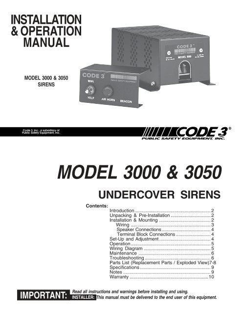
MODEL 3000 & 3050 SIRENS - Code 3 Public Safety Equipment
MODEL 3000 & 3050 SIRENS - Code 3 Public Safety Equipment
MODEL 3000 & 3050 SIRENS - Code 3 Public Safety Equipment
- No tags were found...

Create successful ePaper yourself
Turn your PDF publications into a flip-book with our unique Google optimized e-Paper software.
WARNING!CONTINUED!!WARNING!Fuses or circuit breakers should be located as close to the power takeoff points as possibleand properly sized to protect the wiring and devices.Particular attention should be paid to the location and method of making electricalconnections and splices to protect these points from corrosion and loss of conductivity.Ground terminations should only be made to substantial chassis components, preferablydirectly to the vehicle battery.The user should install a fuse sized to approximately 125% of the maximum Amp capacityin the supply line to protect against short circuits. For example, a 30 Amp fuse shouldcarry a maximum of 24 Amps. DO NOT USE 1/4" DIAMETER GLASS FUSES AS THEYARE NOT SUITABLE FOR CONTINUOUS DUTY IN SIZES ABOVE 15 AMPS. Circuitbreakers are very sensitive to high temperatures and will "false trip" when mounted in hotenvironments or operated close to their capacity.Speaker ConnectionsDetermine the power rating of your speaker(s) at this point.Speaker Phasing - Whenever two speakers are used from one amplifier (two 58 watt, two 100 watt,or two 100 watt in the PSE200 configuration), they must be phased for maximum performance.Phasing involves connecting both speaker terminals marked #1 on the speaker together andconnecting both speaker terminals marked #2 on the speaker together. Be sure to check thespeaker terminals for the numbers, as the wire colors or speaker installation may be arbitrary.CONNECTION OF A 58 WATT SPEAKER TO THE 100 WATT TERMINAL WILL CAUSETHE SPEAKER TO BURN OUT, AND WILL VOID THE SPEAKER WARRANTY!The sound projection opening should be pointed forward, parallel to the ground, and notobstructed or muffled by structural components of the vehicle. Concealed or under-hoodmounting in some cases will result in a dramatic reduction in performance. To minimize thisreduction, mount the speaker so the sound emitted is projected directly forward andobstruction by vehicle components such as hoses, brackets, grille, etc. is minimized.Electromechanical sirens and electronic siren speakers should be mounted as far from theoccupants as possible using acoustically insulated compartments and isolation mounting tominimize the transmission of sound into the vehicle. It may be helpful to mount the device onthe front bumper, engine cowl or fender; heavily insulate the passenger compartment; andoperate the siren only with the windows closed.Each of these approaches may cause significant operational problems, including loss of sirenperformance from road slush, increased likelihood of damage to the siren in minor collisions,and the inability to hear the sirens on other emergency vehicles. APPROPRIATE TRAININGOF VEHICLE OPERATORS IS RECOMMENDED TO ALERT THEM TO THESEPROBLEMS AND MINIMIZE THE EFFECT OF THESE PROBLEMS DURINGOPERATIONS.Terminal Block Connections(-) - Negative (ground/earth) source of supply.(+) - Application of +12 VDC to this terminal will cause the siren to activate and produce the "Wail"tone.A - (<strong>3050</strong> Only) Application of +12 VDC to this terminal will produce "Air Horn" tone. Power neednot be supplied to (+) to terminal B.B - Application of +12 VDC to this terminal while the siren is energized [+12 VDC on terminal (+)]will produce the Yelp tone.Common - Speaker common terminal.58 - 58 watt speaker(s) terminal.100 - 100 watt speaker(s) terminal. Note: Connection of a 58 watt speaker to this terminal and thecommon terminal may destroy the speaker.SET-UP AND ADJUSTMENT!WARNING!Any electronic device may create or be affected by electromagnetic interference. Afterinstallation of any electronic device, operate all equipment simultaneously to insure thatoperation is free of interference. The speaker to Common and 58 (58 watt) or common4
Place the switch in the wail or Yelp position and depress the Air Horn button. The Air Hornshould override the wail and Yelp tones.MAINTENANCEYour <strong>Code</strong> 3 ® <strong>3000</strong>/<strong>3050</strong> SERIES siren has been designed to provide trouble free service. In case ofdifficulty, see the troubleshooting guide below. Also check for shorted or open wires. The primary cause ofshort circuits has been found to be wires passing through firewalls, roofs, etc. The following periodicmaintenance is, recommended:A. Check all terminals and connections to insure that they are tight.B. Remove the siren cover and blow out any accumulated dust or dirt.C. Inspect the speaker to insure that it is not clogged with dirt, leaves, etc.A schematic wiring diagram and technical description are available from the factory upon request.TROUBLESHOOTING(Refer to wiring diagram page 5)PROBLEM PROBABLE CAUSE REMEDYNO OUTPUTEXTERNAL 14AFUSE BLOWS.A. SIREN NOT CONNECTED TOPOWER SOURCEB. EXTERNAL 14A FUSE MISSING/OPENC. VEHICLE SUPPLY FUSE OPENA. SPEAKER(S) SHORTEDA. CHECKCONNECTIONSB. REPLACE FUSEC. REPLACE FUSEA. REPLACESPEAKER(S)NO OUTPUT FROMSPEAKER, TONESHEARD INSIDEAMP. MODULE.SIREN TONESVOLUME TOOLOW/GARBLED.SIREN RUNS PROPERLYBUT SHUTS DOWNWHILE RUNNING, THENSTARTS RUNNINGAGAIN AFTER A FEWMINUTESA. SPEAKER NOT CONNECTED/OPEN CIRCUIT IN SPEAKER WIRINGB. SPEAKER(S) OPENEDA. LOW VOLTAGE TO SIRENAMPLIFIERB. DEFECTIVE SPEAKER/ HIGHRESISTANCE IN WIRINGC. SPEAKERS PHASED IMPROPERLYA. VEHICLE CIRCUIT BREAKERSNOT RATED PROPERLY, AND AREOVERHEATINGA. CHECK SPEAKERWIRINGB. REPLACESPEAKER(S)A. CHECK WIRING FORBAD CONNECTIONS/CHECK VEHICLECHARGING SYSTEMB. CHECK SPEAKER(S)WIRING/REPLACESPEAKER(S)C. REFER TO PAGE 4FOR PROPER PHASINGA. REFER TOSPECIFICATIONSSECTION, PAGE 9. USEA BREAKER WITH ATLEAST TWICE THEAMPERAGE RATINGFOR THE WATTAGEBEING USED. (I.E. 200WATT = 30 A MIN.)6
Parts ListRef No. Description Part No. Qty.1 Siren Cover - Model <strong>3000</strong> S91010M 1- Model <strong>3050</strong> S91011M2 #8 x 3/8 Sheet Metal Screw T00243 43 Circuit Board - Model <strong>3000</strong> T50054 1- Model <strong>3050</strong> T500554 #4-40 Nut T00393 65 #8-32 Nut T00674 26 #8 Spacer T00762 27 #4-40 Hex Spacer T00760 48 #4-40 Ext. Tooth Screw T01086 29 #4 Lockwasher T00677 210 Rivet Burr (Washer) T00095 611 Power Transistor Insulator Pad T00618 212 Electrical Transistor Paper Insulator T01067 213 Transistor T07639 214 #4-40 Machine Screw T00679 415 #8-32 Machine Screw T00763 216 Transistor Cover T00952 2Parts Not ShownSiren ID Serial Number T00765 1Teflon Sleeve T01233 4Parts Bag - Model <strong>3000</strong> T04672 1- Model <strong>3050</strong> T04673 1Switch, DPDT, Center Off W/Jumper (<strong>3000</strong> and <strong>3050</strong>) T00766 1Switch, SPST, White Push Button (<strong>3050</strong> Only) T00773 17
SpecificationsInput Voltage - 10 to 16 VDC, negative ground (earth).(Note: Operation above 15 VDC for an extended period of time may result in speaker damage.)Operating Current:Cycle Rate:Frequency:One 58 watt speaker - 5.5 AmpsTwo 58 watt speakers - 9 AmpsOne 100 watt speaker - 9 AmpsTwo 100 watt speakers - 15 AmpsWAIL - 11 cycles/minute.YELP - 200 cycles/minute.WAIL - 650 to 1800 Hz.YELP - 650 to 1800 Hz.Notes:9
WARRANTYThis product was tested and found to be operational at the time of manufacture. Provided this product isinstalled and operated in accordance with the manufacturer's recommendations, <strong>Code</strong> 3, Inc. guarantees all partsand components except the lamps for a period of 1 year from the date of purchase or delivery, whichever is later.Units demonstrated to be defective within the warranty period will be repaired or replaced at the factory servicecenter at no cost.Use of a lamp or other electrical load of a wattage higher than installed or recommended by the factory, oruse of inappropriate or inadequate wiring or circuit protection causes this warranty to become void. Failure ordestruction of the product resulting from abuse or unusual use and/or accidents is not covered by this warranty.<strong>Code</strong> 3, Inc. shall in no way be liable for other damages including consequential, indirect or special damageswhether loss is due to negligence or breach of warranty.CODE 3, INC. MAKES NO OTHER EXPRESS OR IMPLIED WARRANTY INCLUDING, WITHOUTLIMITATION, WARRANTIES OF FITNESS OR MERCHANTABILITY, WITH RESPECT TO THIS PRODUCT.PRODUCT RETURNSIn order to provide you with significantly faster service, if you are going to return a product for repair orreplacement*, please contact our factory to obtain a Return Goods Authorization Number (RGA number) before youmail the product to <strong>Code</strong> 3, Inc. Write the RGA number clearly on the package near the mailing label. Be sure youuse sufficient packing materials to avoid damage to the product being returned while in transit. All plastic domes andoptical lenses are NOT returnable for credit or exchange.*<strong>Code</strong> 3, Inc. reserves the right to repair or replace product at its discretion. PSE assumes no responsibility or liability for expenses incurred for the removal and/orreinstallation of products requiring service and/or repair.PROBLEMS OR QUESTIONS? CALL OUR TECHNICAL ASSISTANCE HOTLINE (314) 996-2800<strong>Code</strong> 3, Inc.10986 N. Warson RoadSt. Louis, Missouri 63114-2029—USAPh. (314) 426-2700 Fax (314) 426-1337www.code3pse.com<strong>Code</strong> 3 is a registered trademark of <strong>Code</strong> 3, Inc. a subsidiary of <strong>Public</strong> <strong>Safety</strong> <strong>Equipment</strong>, Inc.3M is a registered trademark of 3M Company, Inc.Revision 9, 11/05- Instruction Book Part No. T00820©2005 <strong>Public</strong> <strong>Safety</strong> <strong>Equipment</strong>, Inc. Printed in USA