Installation - Ferraz Fuses & Mersen Products
Installation - Ferraz Fuses & Mersen Products
Installation - Ferraz Fuses & Mersen Products
- No tags were found...

You also want an ePaper? Increase the reach of your titles
YUMPU automatically turns print PDFs into web optimized ePapers that Google loves.
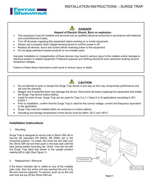
INSTALLATION INSTRUCTIONS – SURGE TRAPDANGERHazard of Electric Shock, Burn or explosion• This equipment must be installed and serviced only by qualified electrical personnel in accordance with Nationaland Local Electrical Codes.• Turn off all power supplying this equipment before working on or inside equipment.• Always use a properly rated voltage-sensing device to confirm power is off.• Replace all devices, doors and covers before restoring power to this equipment• Do not apply petroleum-based products to non-metallic parts.Improper installation or misapplication of these devices may result in serious injury to the installer and/or damage toelectrical system or related equipment. Protective eyewear and clothing should be worn whenever working aroundhazardous voltages.Failure to follow these instructions could result in serious injury or death.CAUTION• Do not attempt to open or tamper the Surge Trap device in any way as this may compromise performance andwill void the warranty.• Megger and hi-potential tests may damage the device. Disconnect all power supplying the equipment and isolatethe Surge Trap device before testing.• Install for point-of-use. Surge Trap can be used for Type 2 or 3 / Class II or III applications according to IEC61643-1.• Prior to installation, confirm that the Surge Trap is rated for the correct voltage, current and frequency equivalentto the application.• Surge Trap must be installed within an enclosure or control cabinet.• Operating and storage temperature of this device must be within -25°C and +60°C.<strong>Installation</strong> Instructions1. MountingSurge Trap is designed to mount onto a 35mm DIN rail ortop-hat rail (standard EN 50022, BS 5584) set in thehorizontal position. To install, first hook the line side overthe 35mm DIN rail and then push in the load side until theblue spring loaded mounting clip “clicks” onto the rail withthe Surge Trap label text shown in the upright positionreading left to right (See Figure 1).2. Replacement / RemovalIf the blown indicator tab is visible on any of the multiplepole units, then the entire unit has reached the end of itslife and must be replaced. To remove, push up on the unitand rock the top off the 35mm DIN rail. Figure 1
3. Wire <strong>Installation</strong>#6 − #14 AWG wire may be used. Maximum torque to beapplied to terminal screws is 14.75 in-lb. Strip back wireinsulation 8mm (5/16”).Interconnecting wire should be no longer than 500mm(20”) in total length. Wire bending radius should be >100mm (4”). Do not loop or twist interconnecting wire.Failure to meet these requirements will result in higherlet-through voltages.4. Auxiliary Micro-Switch <strong>Installation</strong>Remote signaling is available on all Surge Trap productsthat specify a remote indicator. #16 − #30 AWG signalwire may be used. Maximum torque rating for the terminalscrew is 1.80 in-lb. The maximum continuous currentrating for the remote indicator is 3A.If applicable, install signal wiring as shown in Figure 3.Surge Trap is installed in parallel with the load or theelectrical system wiring.Determine electrical voltage configuration and propermodes of protection and install wiring as shown in Figure2.Figure 3Figure 2NOTE: SURGE TRAP DOES NOT REQUIRE ANY ADDITIONAL OVERCURRENT PROTECTIONNO ADDITIONAL FUSING REQUIRED<strong>Ferraz</strong> Shawmut, Inc. Surge Trap meets all requirements set forth by UL 1449 2005 Edition effectiveFebruary 9, 2007. Reference UL file number E210793.XXXXXXREV. 0