Elign Gear Couplings - Benzlers
Elign Gear Couplings - Benzlers
Elign Gear Couplings - Benzlers
You also want an ePaper? Increase the reach of your titles
YUMPU automatically turns print PDFs into web optimized ePapers that Google loves.
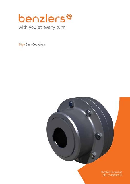
<strong>Elign</strong> <strong>Gear</strong> <strong>Couplings</strong>Flexible <strong>Couplings</strong>CEL-2.00GB0312
°ELIGN COUPLINGSGEAR COUPLINGSINTRODUCTIONA <strong>Gear</strong> Coupling is used to join two rotating shafts for efficient transmission of mechanical power. Although the shafts are accuratelyaligned at the time of installation, it is likely that during the operation the alignment may get disturbed due to settingof foundation, thermal expansion, shaft deflection, wearing out of other parts, improper maintenance and many more reasons.Due to this unavoidable misalignment occurring during the operation a gear coupling provides a better solution to compensateor minimise the effect of misalignment. The gear <strong>Couplings</strong> are therefore ideally suited for wide range of application in theentire field of drive technology.MISALIGNMENTThe main function of any <strong>Gear</strong> coupling is not only to connect two rotating shafts but also to accommodate misalignments ofthe connecting shafts ELIGN <strong>Gear</strong> coupling accommodates the following three types of misalignment.A. RadialFUNCTIONSMISALIGNMENTWhen axes of connected shafts areparallel but not in the same straightline.AAB. AngularWhen axes of connected shaftsintersect at the centre point of thecoupling but not in the same straightline.BBC. Combined radial and angular.When the axes of connected shaftsdo not intersect at the point of thecoupling and are not parallel.CCBesides the above three types of misalignment, the ELIGN <strong>Gear</strong> coupling range also permit axial movement of the shaft.CAUTION.Normally permissible angular misalignment of ELIGN gear coupling is 0.75 for each half. However, it does not mean that themisalignment should be permitted to this limit from the initial installation. Since misalignment can occur during operation the<strong>Elign</strong> gear coupling takes care of this without undue damage to the connected equipment. However the coupling’s life may reducedue to relative motion between hub teeth and housing teeth causing increased wear on the teeth. It is therefore extremelyimportant to align the interconnecting shafts precisely during initial installation.1
ELIGN COUPLINGSORDERING INFORMATIONORDERING INFORMATIONWHEN ORDERING, PLEASE SPECIFY THE FOLLOWING INFORMATION1. Quantity and delivery requirements2. Shaft or bore sizes and keyway dimensions. Give exact dimensions with tolerances.3. Load — Horsepower and/or torque at a specific RPM. State normal and maximum conditions.4. Speed — minimum, normal and maximum.5. Application — type of driver and driven equipment.6. Coupling Series, Type and Size.7. Space limitations — envelope dimensions, shaft extensions and shaft spacing.8. Unusual misalignment conditions.9. Modifications — tapered bores, special keys, hub cut off, counterbores or others10. Unusual operating conditions ambient temperatures and atmospheres.SELECTION1. Obtain Shaft Sizes, compare shaft sizes of driving and driven equipment with listed maximum bores of desired series or typeof coupling to determine “tentative” coupling size.2. Compute effective kW/rpm or torque to be transmitted and select a service factor from adjacent tableDetermine kW/rpm (effective)= kW TRANSMITTED X SERVICE FACTORrpmor determine Torque daNmTorque (effective) daNm= 955 X kW TRANSMITTED X SERVICE FACTORrpmConfirm “Tentative” Coupling size or increase to a size which has a kW/rpm torque rating equal to or greater than the valuecreated above.3. Check the maximum speed of the application and refer to maximum speed ratings. These speeds are given only as a guidesince the maximum speed depends on the application characteristics.4. Check space limitations and the dimensions of the selected coupling should be compared with the space provided in theapplication to ensure proper clearances. Shaft extensions, separation, and clearances to align coupling should be checked.Lifting HoleThe hubs of the couplings from size ED1600 upwards are supplied with lifting holes to allow for easy lifting of the coupling.LubricationEach coupling half is provided with grease nipple/plug on the housing from where grease can be filled directly.The couplings are supplied with some quality of grease to facilitate assembly. It is recommended to fill the required quality andquantity of grease before putting the coupling in operation.Special ProtectionAll the components of the ELIGN gear couplings have a special rust preventative oil coating, in addition to all the nuts andbolts which are zinc/cadmium plated to further protect against rust & corrosion.
ELIGN COUPLINGSTYPE ED (SUPER SERIES)Multi Crowned Toothed <strong>Couplings</strong> For Shaft Connections Type ED (SUPER SERIES)M1M1GGE, PCD2 HOLES, S x TOBLN1LOCODOAARRANGEMENT FOR ED- 75000 AND ONWARDSL N2 L L N3 L L N4 LSize TkN Tk maxContinuous shockPkNnconti.ADiameter Length Tapping MisalignmentBC D L M1 N1 N2 N3 N4 E SxTpilot min. MaxiRRWeightkgMomentsof Inertia(kgm2)MaximumADMSpeed1/mindaNm daNm kW/rpm mm mm degree ± mm kg (kgm2) 1/minED 25200 50400 26.39 632 155 160 310 422 550 280 10 15 119 223 346 360 M20x30 2x0.75 1.8 670 26.75 1830ED 29000 58000 30.366 640 195 200 320 432 518 292 6.5 13 33 53 255 380 M20x30 2x0.75 2.1 760 31 1800ED 37000 74000 38.746 715 205 210 355 472 616 310 12 20 133 246 383 410 M24x40 2x0.75 2.2 930 48 1460ED 45000 90000 47.123 750 225 230 370 502 648 330 11.5 20 144 268 408 435 M24x40 2x0.75 2.2 1110 65.8 1395ED 56000 112000 58.639 804 275 280 450 594 682 350 6.5 13 61 109 335 544 M24x40 2x0.75 2.7 1532 105 1300ED 75000 150000 78.539 910 285 290 480 620 812 410 10.5 25 121 217 * 550 M36x55 2x0.75 3 2180 198 1000ED 90000 180000 94.247 980 315 320 515 670 860 430 15.5 25 102 179 * 585 M36x55 2x0.75 3 2520 265 940ED 110000 220000 115.19 1020 325 330 540 700 908 450 16 25 97 169 * 615 M36x55 2x0.75 4 2910 333 9001. SPACE REQUIRED TO CHANGE THE SEAL2. KEYWAYS ACCORDING TO DIN:6885 PART-13. MAXIMUM ANGULAR MISALIGNMENT PER COUPLING HALF 0.754. WEIGHT & MOMENT OF INERTIA BASED ON PILOT BORE CONDITION.5. CONTINUOUS TORQUE RATING SUBJECT TO ACCURATE ALIGNMENT OF CONNECTING SHAFTS.6. FOR A HIGHER SIZE REQUIREMENT, PLEASE CONTACT APPLICATION ENGINEERING.7. FOR MARKED DIMENSIONS, PLEASE CONTACT APPLICATION ENGINEERING.In accordance with our established policy to constantly improve our products, these specifications are subject to change withoutnotice.7
Multi Crowned Toothed <strong>Couplings</strong> For Shaft Connections Type ERELIGN COUPLINGSTYPE EROAODOCE, PCD2 HOLE, S x T @180°OBLN1LOB1E1, PCD2 HOLE, S x TOD1Size TkN Tk maxContinuous shockPkNnconti.ADiameter Length TappingBB1C D D1 L L1 M1 N1 E E1 SxTpilot min. Maxi pilot min. MaxiRRWeight MomentsofInertiaMaximumADMSpeeddaNm daNm kW/rpm mm mm mm degree Kg j (kgm2) 1/minER 130 260 0.136 111 10 15 45 10 15 55 67 80 80 43 40 74 5 - - - 0.75 4 0.005 7000ER 280 560 0.293 141 15 20 60 15 20 75 87 103.5 103.5 50 47 84 5 - - - 0.75 8 0.015 6200ER 500 1000 0.524 171 25 30 75 25 30 95 106 129.5 126 62 58 105 5 - - - 0.75 14 0.039 5650ER 1000 2000 1.047 210 30 35 95 30 35 110 130 156 152 76 74 123 6 - - - 0.75 26 0.102 5100ER 1600 3200 1.675 234 35 40 110 35 40 130 151 181 178 90 87 148 6 130 155 M8x12 0.75 38 0.196 4700ER 2200 4400 2.304 274 50 55 130 50 55 155 178 209 208 105 101 172 6.5 155 180 M8x12 0.75 61 0.45 4350ER 3200 6400 3.351 312 60 65 155 60 65 180 213 247 245 120 113 193 6.5 185 210 M10x15 0.75 91 0.871 4000ER 4500 9000 4.712 337 75 80 175 75 80 200 235 273 270 135 129 215 8 205 235 M12x18 0.75 120 1.368 3800ER 6200 12400 6.492 380 85 90 195 85 90 230 263 307 305 150 150 241 8 226 265 M16x24 0.75 175 2.586 3600ER 8400 16800 8.796 405 95 100 215 95 100 250 286 338 330 175 175 279 8 250 290 M16x24 0.75 232 3.91 3450ER 11500 23000 12.042 444 115 120 240 115 120 280 316 368 362 190 190 304 10 276 320 M16x24 0.75 287 5.655 3300ER 17400 34800 18.221 506 145 150 275 145 150 330 372 426 416 220 220 339 13 330 370 M20x30 0.75 430 11.5 30501 SPACE REQUIRED TO CHANGE THE SEAL2 KEYWAYS ACCORDING TO DIN:6885 PART-13 MAXIMUM ANGULAR MISALIGNMENT 0.754 WEIGHT & MOMENT OF INERTIA BASED ON PILOT BORE CONDITION.5 CONTINUOUS TORQUE RATING SUBJECT TO ACCURATE ALIGNMENT OF CONNECTING SHAFTS.6 FOR A HIGHER SIZE REQUIREMENT, PLEASE CONTACT APPLICATION ENGINEERING..In accordance with our established policy to constantly improve our products, these specifications are subject to change withoutnotice.8
ELIGN COUPLINGSTYPE ER (SUPER SERIES)Multi Crowned Toothed <strong>Couplings</strong> For Shaft Connections Type ER (SUPER SERIES)GM1OAODOCE, PCD2 HOLES, S x T @180°OBLN1LOB1E1, PCD2 HOLE, S x TOD1SHAPE OF GEAR HALF FORCOUPLING SIZE 290000Size TkNContinuousTkmaxshockPkNnconti.ABDiameter Length TappingB1pilot min. Maxi pilot min. MaxiC D D1 L G L1 M1 N1 E E1 SxTWeight Moments Maximumof InertiaADMSpeeddaNm daNm kW/rpmmm mm mm Degree kg (kgm2) 1/minER 25200 50400 26.39 632 155 160 310 155 160 340 422 550 470 280 10 280 335 12 360 395 M20x30 0.75 706 26.17 1830ER 29000 58000 30.366 640 195 200 320 195 200 365 432 518 512 292 6.5 292 324 14.5 380 455 M20x30 0.75 820 33.53 1880ER 37000 74000 38.746 715 205 210 355 205 210 380 472 616 535 310 12 310 370 16.5 410 445 M24x40 0.75 984 48.26 1460ER 45000 90000 47.123 750 225 230 370 225 230 410 502 648 570 330 11.5 330 395 16.5 435 480 M24x40 0.75 1170 64.04 1395RR1 SPACE REQUIRED TO CHANGE THE SEAL2 KEYWAYS ACCORDING TO DIN:6885 PART-13 MAXIMUM ANGULAR MISALIGNMENT PER COUPLING HALF 0.754 WEIGHT & MOMENT OF INERTIA BASED ON PILOT BORE CONDITION.5 CONTINUOUS TORQUE RATING SUBJECT TO ACCURATE ALIGNMENT OF CONNECTING SHAFTS.6 FOR A HIGHER SIZE REQUIREMENT, PLEASE CONTACT APPLICATION ENGINEERING.7 FOR MARKED DIMENSIONS, PLEASE CONTACT APPLICATION ENGINEERING.In accordance with our established policy to constantly improve our products, these specifications are subject to change withoutnotice.9
Multi Crowned Toothed <strong>Couplings</strong> For Shaft Connections Type ETELIGN COUPLINGSTYPE ETM1M1ROO = N-2 (R-L)RPCE, PCD2 HOLE, S x TBLNPLEASE QUOTEBE, PCD2 HOLE, S x TDASize TkNContinuousdaNmTk maxshockdaNmPkNnconti.ADiameter Length Tapping MisalignmentBpilot min. MaxiC D L M1 P R E SxTWeightMomentsMaximumof InertiaADMSpeeddaNm daNm kW/rpmmm mm mm degree kg (kgm2) 1/minET 130 260 0.136 111 10 15 45 67 80 43 74 16 53.5 - - 0.75 1.5 4 0.005ET 280 560 0.293 141 15 20 60 87 103.5 50 84 13 57.5 - - 0.75 1.5 8 0.0015ET 500 1000 0.524 171 25 30 75 106 129.5 62 104 20 77.5 - - 0.75 1.5 14 0.039ET 1000 2000 1.047 210 30 35 95 130 156 76 123 20 90.5 - - 0.75 2.5 25 0.101ET 1600 3200 1.675 234 35 40 110 151 181 90 148 22 106.5 130 M8x12 0.75 2.5 37 0.188ET 2200 4400 2.304 274 50 55 130 178 209 105 172 25 125 155 M8x12 0.75 3 60 0.431ET 3200 6400 3.351 312 60 65 155 213 247 120 192 26 141 185 M10x15 0.75 3 90 0.845ET 4500 9000 4.712 337 75 80 175 235 273 135 216 31 160 205 M12x18 0.75 4 118 1.322ET 6200 12400 6.492 380 85 90 195 263 307 150 241 33 178 226 M16x24 0.75 4 168 2.45ET 8400 16800 8.796 405 95 100 215 286 338 175 279 40 210 250 M16x24 0.75 4 224 3.72ET 11500 23000 12.042 444 115 120 240 316 368 190 304 47 232 276 M16x24 0.75 4 277 5.39RRLIMITED BY THE CRITICAL SPEED ANDWEIGHT OF THE INTERMEDIATE HOLLOWSHAFT1 SPACE REQUIRED TO CHANGE THE SEAL2 KEYWAYS ACCORDING TO DIN:6885 PART-13 MAXIMUM ANGULAR MISALIGNMENT PER COUPLING HALF 0.754 WEIGHT & MOMENT OF INERTIA WITHOUT INTERMEDIATE HOLLOW SHAFT.5 CONTINUOUS TORQUE RATING SUBJECT TO ACCURATE ALIGNMENT OF CONNECTING SHAFTS.6 FOR A HIGHER SIZE REQUIREMENT, PLEASE CONTACT APPLICATION ENGINEERING.In accordance with our established policy to constantly improve our products, these specifications are subject to change withoutnotice.10
ELIGN COUPLINGSTYPE ET (SUPER SERIES)Multi Crowned Toothed <strong>Couplings</strong> For Shaft Connections Type ET (SUPER SERIES)M1M1RRPPCE, PCD2 HOLE, S x TBLNPLEASE QUOTELBE, PCD2 HOLE, S x TDASHAPE OF COUPLINGFOR SIZE 29000 & 56000Size TkNContinuousdaNmTk maxshockdaNmPkNnconti.ADiameter Length Tapping MisalignmentBC D L M1 P R E SxTpilot min. MaxiRRWeightkgMomentsof Inertia(kgm2)MaximumADMSpeed1/mindaNm daNm kW/rpm mm mm mm Degree kg (kgm2) 1/minET 25200 50400 26.39 632 155 160 310 422 550 280 335 119 391.5 360 M20x30 0.75 10 670 26.75ET 29000 58000 30.366 640 195 200 320 432 518 292 324 33 318.5 380 M20x30 0.75 6.5 760 31ET 37000 74000 38.746 715 205 210 355 472 616 310 370 133 433 410 M24x40 0.75 12 930 48ET 45000 90000 47.123 750 225 230 370 502 648 330 395 144 464 435 M24x40 0.75 11.5 1110 65.8ET 56000 112000 58.639 804 275 280 450 594 682 350 379 61 404.5 544 M24x40 0.75 6.5 1532 105ET 75000 150000 78.539 910 285 290 480 620 812 410 485 121 521.5 550 M36x55 0.75 10.5 2180 198ET 90000 180000 94.247 980 315 320 515 670 860 430 510 102 523.5 585 M36x55 0.75 15.5 2520 265ET 110000 220000 115.19 1020 325 330 540 700 908 450 530 97 539.5 615 M36x55 0.75 16 2910 333LIMITED BY THE CRITICALSPEED AND WEIGHT OF THEINTERMEDIATE HOLLOW SHAFT1 SPACE REQUIRED TO CHANGE THE SEAL2 KEYWAYS ACCORDING TO DIN:6885 PART-13 MAXIMUM ANGULAR MISALIGNMENT PER COUPLING HALF 0.754 WEIGHT & MOMENT OF INERTIA WITHOUT INTERMEDIATE HOLLOW SHAFT.5 CONTINUOUS TORQUE RATING SUBJECT TO ACCURATE ALIGNMENT OF CONNECTING SHAFTS.6 FOR A HIGHER SIZE REQUIREMENT, PLEASE CONTACT APPLICATION ENGINEERING.In accordance with our established policy to constantly improve our products, these specifications are subject to change withoutnotice.11
Multi Crowned Toothed <strong>Couplings</strong> For Shaft Connections Type EVOAODOCELIGN COUPLINGSTYPE EVTOP SIDEBOTTOM SIDEM1 M1N1 N2LLOBNN1E, PCD2 HOLE, S x T @180°Size TkNContinuousTk maxshockPkNnconti.ADiameter Length Tapping MisalignmentBC D L M1 N N1 N2 E SxTpilot min. MaxiRRWeightMomentsMaximumof InertiaADMSpeeddaNm daNm kW/rpm mm mm mm kg (kgm2) 1/minEV 130 260 0.136 111 10 15 45 67 80 43 74 8 1.5 5.5 - - 2x0.75 0.35 4.5 0.0057 5000EV 280 560 0.293 141 15 20 60 87 103.5 50 84 5 1.5 5.5 - - 2X0.75 0.4 8.5 0.017 4400EV 500 1000 0.524 171 25 30 75 106 129.5 62 105 12.5 1.5 6 - - 2X0.75 0.5 15 0.043 4000EV 1000 2000 1.047 210 30 35 95 130 156 76 123 11 2.5 8.5 - - 2X0.75 0.6 26 0.11 3600EV 1600 3200 1.675 234 35 40 110 151 181 90 148 13 2.5 8.5 130 M8X12 2X0.75 0.7 39 0.206 3350EV 2200 4400 2.304 274 50 55 130 178 209 105 172 14 3 12 155 M8X12 2X0.75 0.9 61 0.461 3100EV 3200 6400 3.351 312 60 65 155 213 247 120 193 15 3 12 185 M10X15 2X0.75 1 93 0.935 2800EV 4500 9000 4.712 337 75 80 175 235 273 135 215 17 4 16 205 M12X18 2X0.75 1.1 122 1.454 2700EV 6200 12400 6.492 380 85 90 195 263 307 150 241 20 4 16 226 M16X24 2X0.75 1.2 175 2.71 2550EV 8400 16800 8.796 405 95 100 215 286 338 175 279 27 4 16 250 M16X24 2X0.5* 0.9 236 4.32 2450EV 11500 23000 12.042 444 115 120 240 316 368 190 304 34 4 16 276 M16X24 2X0.5* 1 295 6.48 2300EV 17400 34800 18.221 506 145 150 275 372 426 220 339 28 5 20 330 M20X30 2X0.5* 1.1 430 11 21501 SPACE REQUIRED TO CHANGE THE SEAL2 KEYWAYS ACCORDING TO DIN:6885 PART-13 MAXIMUM ANGULAR MISALIGNMENT PER COUPLING HALF 0.754 WEIGHT & MOMENT OF INERTIA BASED ON PILOT BORE CONDITION.5 CONTINUOUS TORQUE RATING SUBJECT TO ACCURATE ALIGNMENT OF CONNECTING SHAFTS.* MAXIMUM ANGULAR MISALIGNMENT PER COUPLING HALF 0.56 FOR A HIGHER SIZE REQUIREMENT, PLEASE CONTACT APPLICATION ENGINEERING.In accordance with our established policy to constantly improve our products, these specifications are subject to change withoutnotice.12
Multi Crowned Toothed <strong>Couplings</strong> For Shaft Connections Type ESELIGN COUPLINGSTYPE ESM1N 1/2N 1/2E, PCD2 HOLE, S x T @180°OBLNLOCOASize TkNContinuousTkmaxshockPkNnconti.ADiameter Length Tapping MisalignmentBpilot min. MaxiC L M1 N E SxTWeightkgMomentsof Inertia(kgm2)MaximumADMSpeed1/mindaNm daNm kW/rpmmm mm mm Degree kg (kgm2) 1/minES 1600 3200 1.675 186 35 40 110 151 90 218 5 130 M8x12 2x0.75 0.7 34 0.158 4700ES 2200 4400 2.304 216 50 55 130 178 105 257 6 155 M8x12 2x0.75 0.9 52 0.332 4350ES 3200 6400 3.351 254 60 65 155 213 120 289 6 185 M10X15 2X0.75 1 82 0.738 4000ES 4500 9000 4.712 282 75 80 175 235 135 325 8 205 M12X18 2X0.75 1.1 112 1.255 3800ES 6200 12400 6.492 317 85 90 195 263 150 358 8 226 M16X24 2X0.75 1.2 154 2.197 3600ES 8400 16800 8.796 346 95 100 215 286 175 419 8 250 M16X24 2X0.75 1.4 209 3.51 3450ES 11500 23000 12.042 376 115 120 240 316 190 459 8 276 M16X24 2X0.75 1.5 264 5.352 3300ES 17400 34800 18.221 436 145 150 275 372 220 513 10 330 M20X30 2X0.75 1.7 398 11 3050RR1 SPACE REQUIRED TO CHANGE THE SEAL2 KEYWAYS ACCORDING TO DIN:6885 PART-13 MAXIMUM ANGULAR MISALIGNMENT PER COUPLING HALF 0.754 WEIGHT & MOMENT OF INERTIA BASED ON PILOT BORE CONDITION.5 CONTINUOUS TORQUE RATING SUBJECT TO ACCURATE ALIGNMENT OF CONNECTING SHAFTS.6 FOR HIGHER SIZE REQUIREMENT PLEASE CONTACT US.In accordance with our established policy to constantly improve our products, these specifications are subject to change withoutnotice.13
CONTACT USAUSTRALIADENMARKSWEDEN & NORWAYUNITED KINGDOMRadicon Transmission(Australia) PTY LtdAustraliaTel: +61 488 054 028EUROPEBenzler TBA BVJachthavenweg 2NL-5928 NT VenloAustriaTel: +43 7 229 618 91Fax: +43 7 229 618 84FranceTel: +33 687 718 711Fax: +31 77 324 59 01GermanyTel: 0800 350 40 00Fax: 0800 350 40 01ItalyTel: +39 02 824 3511Benzler Transmission A/SFuglebævej 3DDK-2770 Kastrup,DenmarkTel: +45 36 34 03 00Fax: +45 36 77 02 42FINLANDOy Benzler ABVanha Talvitie 3CFI-00580 Helsingfors,FinlandTel: +358 9 340 1716Fax: +358 10 296 2072INDIAElecon. EngineeringCompany Ltd.Anand Sojitra RoadVallabh Vidyanagar388120 GujaratIndiaAB <strong>Benzlers</strong>Box 922 (Landskronavägen 1)251 09 HelsingborgSwedenTel: +46 42 18 68 00Fax: +46 42 21 88 03THAILANDRadicon Transmission(Thailand) Ltd700/43 Moo 6Amata Nakorn Industrial EstateTumbol KlongtumruMuang,Chonburi20000ThailandTel: +66 3845 9044Fax: +66 3821 3655Radicon Transmission UK LtdUnit J3Lowfields Business Park,Lowfields Way, EllandWest Yorkshire, HX5 9DATel: +44 (0) 1484 465 800Fax: +44 (0) 1484 465 801USARadicon USA Transmission Ltd1599 Lunt AvenueElk Grove VillageChicagoIllinois60007USATel: +1 847 593 9910Fax: +1 847 593 9950Netherlands & the rest of EuropeTel: +31 77 324 59 00Fax: +31 77 324 59 01Tel: +91 2692 23651Fax: +91 2692 227484www.benzlers.comwww.radicon.comTechnicalUp to - 100kW / 8500 NmWorm <strong>Gear</strong>sCAM-1.00GB0111
<strong>Benzlers</strong>Denmark +45 36 34 03 00Finland +358 9 340 1716Germany +49 800-350 4000Sweden +46 42 186800The Netherlands +31 77 324 59 00www.benzlers.comRadiconThailand +66 3845 9044United Kingdom +44 (0) 1484 465 800USA +1 847 593 9910www.radicon.com


