AC Resistance Bridge
AC Resistance Bridge
AC Resistance Bridge

You also want an ePaper? Increase the reach of your titles
YUMPU automatically turns print PDFs into web optimized ePapers that Google loves.
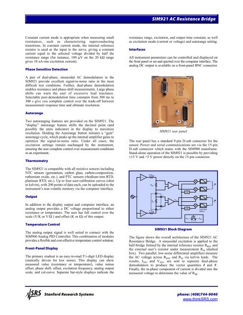
SIM921 <strong>AC</strong> <strong>Resistance</strong> <strong>Bridge</strong>Constant current mode is appropriate when measuring smallresistances, such as characterizing superconductingtransitions. In constant current mode, the internal referenceresistor is used as the input to the servo, giving a constantcurrent equal to the selected voltage divided by half theresistance range (for instance, 100 µV on the 20 kΩ rangegives 10 nA rms excitation current).Phase Sensitive Detectionresistance range, excitation, and output time constant, as wellas excitation mode (current or voltage) and autorange setting.InterfacesAll instrument parameters can be controlled and displayed onthe front panel or set and queried over the computer interface. Theanalog DC output is available on a front-panel BNC connector.A pair of dual-phase, sinusoidal <strong>AC</strong> demodulators in theSIM921 provide excellent signal-to-noise ratio in the mostdifficult test conditions. Further, dual-phase demodulationenables resistance and phase-shift measurements. Large phaseshifts can warn the user of excessive lead reactance.Selectable post-demodulation time constants from 300 ms to300 s give you complete control over the trade-off betweenmeasurement response time and ultimate resolution.AutorangeTwo autoranging features are provided on the SIM921. The“display” autorange feature shifts the decimal point (andpossibly the units indicator) in the display to maximizeresolution. Holding the Autorange button initiates a “gain”autorange cycle, which peaks up the internal amplifier gains tooptimize the signal-to-noise ratio. Under all cases, theexcitation settings remain unchanged by the instrument,ensuring the user complete control over measurement conditionsin an experiment.ThermometrySIM921 rear panelThe rear panel has a standard 9-pin D-sub connector for thesensor. Power and serial communications are via the 15-pinD-sub connector which mates with the SIM900 mainframe.Stand-alone operation of the SIM921 is possible by providing±15 V and +5 V power directly on the 15-pin connector.The SIM921 is compatible with all resistive sensors includingNTC sensors (germanium, carbon glass, carbon-composition,ruthenium oxide, etc.), and PTC sensors (rhodium-iron RTD,platinum RTD, etc.). Up to four user-calibration curves (ohmto kelvin), with 200 points of data each, can be uploaded to theinstrument’s non-volatile memory via the computer interface.×110 R REFR REFI XI YII SIG+90°OutputIn addition to the display output and computer interface, ananalog output provides a DC voltage proportional to eitherresistance or temperature. The user has full control over thescale (V/K or V/Ω ) and offset (K or Ω) of this output.Temperature ControlThe analog output signal is well suited to connect with theSIM960 Analog PID Controller. This combination of modulesprovides a flexible and cost-effective temperature control solution.Front-Panel DisplayThe primary readout is an easy-to-read 5½-digit LED display(statically driven for low noise). This display can showmeasured value (resistance or temperature), value minusoffset, phase shift, offset, excitation frequency, analog outputscale, and cal-curve. Separate bar-style displays indicate the×−1R M14V SIG511 R 2REF+90°SIM921 Block DiagramV 2R M = × R REFI VLow PassFiltersThe figure shows the overall architecture of the SIM921 <strong>AC</strong><strong>Resistance</strong> <strong>Bridge</strong>. A sinusoidal excitation is applied to thehalf-bridge formed by the internal reference resistor R REF andthe external user’s resistor under measurement R M (dashedbox). Two parallel, low-noise differential amplifiers measurethe <strong>AC</strong> voltage across R REF and R M via kelvin leads. Theresults, I SIG and V SIG , are sent to separate dual-phasedemodulators to produce the vector quantities I and V.Finally, the in-phase component of current is divided into themeasured voltage to determine the value of R M .V XV YVStanford Research Systems phone: (408)744-9040www.thinkSRS.com