Webot Guide - Ubiquitous Computing Lab
Webot Guide - Ubiquitous Computing Lab
Webot Guide - Ubiquitous Computing Lab

You also want an ePaper? Increase the reach of your titles
YUMPU automatically turns print PDFs into web optimized ePapers that Google loves.
<strong>Webot</strong>s User <strong>Guide</strong>release 4.0.9copyright c○ 2002 Cyberbotics Ltd. All rights reserved.www.cyberbotics.comJuly 28, 2003
Foreword<strong>Webot</strong>s is a three-dimensional mobile robot simulator. It was originally developed as a researchtool for investigating various control algorithms in mobile robotics.This user guide will get you started using <strong>Webot</strong>s. However, the reader is expected to have aminimal knowledge in mobile robotics, in C programming and in VRML 2.0 (Virtual RealityModeling Language).The great innovation of the fourth version of <strong>Webot</strong>s is that it includes a physics engine allowingto define complex mobile robots with various locomotion schemes. Predefined objects likeshapes, sensors and servos allow users to create and run their own simulated robot. Thus, <strong>Webot</strong>sis no longer limited to differentially wheeled robots.The GUI of <strong>Webot</strong>s version 3 has been replaced by wxWindows, an Open Source Free SoftwareGUI toolkit.If you have already developed programs using <strong>Webot</strong>s 3, please read chapter 2 to update yourprograms to run with the new version.We hope that you will enjoy working with <strong>Webot</strong>s 4.3
ThanksCyberbotics is grateful to all the people who contributed to the development of <strong>Webot</strong>s, <strong>Webot</strong>ssample applications, the <strong>Webot</strong>s User <strong>Guide</strong>, the <strong>Webot</strong>s Reference Manual, and the <strong>Webot</strong>s website, including Jordi Porta, Emanuele Ornella, Yuri Lopez de Meneses, Auke-Jan Ijspeert, GeraldFoliot, Allen Johnson, Michael Kertesz, Aude Billiard, and many others.Moreover, many thanks are due to Prof. J.-D. Nicoud (LAMI-EPFL) and Dr. F. Mondada fortheir valuable support.Finally, thanks to Skye Legon, who proof-read this guide.5
Contents1 Installing <strong>Webot</strong>s 111.1 Hardware requirements . . . . . . . . . . . . . . . . . . . . . . . . . . . . . . . 111.2 Installation procedure . . . . . . . . . . . . . . . . . . . . . . . . . . . . . . . . 111.2.1 RedHat Linux i386 . . . . . . . . . . . . . . . . . . . . . . . . . . . . . 111.2.2 Windows 95, 98, ME, NT, 2000 and XP . . . . . . . . . . . . . . . . . . 121.2.3 Mac OS X, version 10.2 . . . . . . . . . . . . . . . . . . . . . . . . . . 121.3 Registration Procedure . . . . . . . . . . . . . . . . . . . . . . . . . . . . . . . 131.3.1 <strong>Webot</strong>s license . . . . . . . . . . . . . . . . . . . . . . . . . . . . . . . 131.3.2 Registering . . . . . . . . . . . . . . . . . . . . . . . . . . . . . . . . . 132 Upgrading from <strong>Webot</strong>s 3 172.1 Controller . . . . . . . . . . . . . . . . . . . . . . . . . . . . . . . . . . . . . . 172.1.1 Controller includes . . . . . . . . . . . . . . . . . . . . . . . . . . . . . 172.1.2 Controller library . . . . . . . . . . . . . . . . . . . . . . . . . . . . . . 172.1.3 Basic data type . . . . . . . . . . . . . . . . . . . . . . . . . . . . . . . 172.1.4 Khepera . . . . . . . . . . . . . . . . . . . . . . . . . . . . . . . . . . . 182.1.5 GTK+ GUI . . . . . . . . . . . . . . . . . . . . . . . . . . . . . . . . . 182.2 World . . . . . . . . . . . . . . . . . . . . . . . . . . . . . . . . . . . . . . . . 183 Getting Started with <strong>Webot</strong>s 213.1 Launching <strong>Webot</strong>s . . . . . . . . . . . . . . . . . . . . . . . . . . . . . . . . . 213.1.1 On Linux . . . . . . . . . . . . . . . . . . . . . . . . . . . . . . . . . . 213.1.2 On Mac OS X . . . . . . . . . . . . . . . . . . . . . . . . . . . . . . . . 213.1.3 On Windows . . . . . . . . . . . . . . . . . . . . . . . . . . . . . . . . 217
8 CONTENTS3.2 Main Window: menus and buttons . . . . . . . . . . . . . . . . . . . . . . . . . 223.2.1 File menu and shortcuts . . . . . . . . . . . . . . . . . . . . . . . . . . . 223.2.2 Edit menu . . . . . . . . . . . . . . . . . . . . . . . . . . . . . . . . . . 243.2.3 Simulation menu and the simulation buttons . . . . . . . . . . . . . . . . 243.2.4 Help menu . . . . . . . . . . . . . . . . . . . . . . . . . . . . . . . . . 253.2.5 Navigation in the scene . . . . . . . . . . . . . . . . . . . . . . . . . . . 253.2.6 Moving a solid object . . . . . . . . . . . . . . . . . . . . . . . . . . . . 263.2.7 Selecting a solid object . . . . . . . . . . . . . . . . . . . . . . . . . . . 263.3 Scene Tree Window . . . . . . . . . . . . . . . . . . . . . . . . . . . . . . . . . 273.3.1 Buttons of the Scene Tree Window . . . . . . . . . . . . . . . . . . . . . 273.3.2 VRML nodes . . . . . . . . . . . . . . . . . . . . . . . . . . . . . . . . 293.3.3 <strong>Webot</strong>s specific nodes . . . . . . . . . . . . . . . . . . . . . . . . . . . 303.3.4 Principle of the collision detection . . . . . . . . . . . . . . . . . . . . . 303.3.5 Writing a <strong>Webot</strong>s file in a text editor . . . . . . . . . . . . . . . . . . . . 313.4 Citing <strong>Webot</strong>s . . . . . . . . . . . . . . . . . . . . . . . . . . . . . . . . . . . . 314 Tutorial: Modeling and simulating your robot 334.1 My first world: kiki.wbt . . . . . . . . . . . . . . . . . . . . . . . . . . . . . . . 334.1.1 Environment . . . . . . . . . . . . . . . . . . . . . . . . . . . . . . . . 334.1.2 Robot . . . . . . . . . . . . . . . . . . . . . . . . . . . . . . . . . . . . 374.1.3 A simple controller . . . . . . . . . . . . . . . . . . . . . . . . . . . . . 474.2 My second world: a kiki robot with a camera . . . . . . . . . . . . . . . . . . . 484.3 My third world: pioneer2.wbt . . . . . . . . . . . . . . . . . . . . . . . . . . . . 494.3.1 Environment . . . . . . . . . . . . . . . . . . . . . . . . . . . . . . . . 494.3.2 Robot with 16 sonars . . . . . . . . . . . . . . . . . . . . . . . . . . . . 494.3.3 Controller . . . . . . . . . . . . . . . . . . . . . . . . . . . . . . . . . . 565 Robot and Supervisor Controllers 595.1 Overview . . . . . . . . . . . . . . . . . . . . . . . . . . . . . . . . . . . . . . 595.2 Setting Up a New Controller . . . . . . . . . . . . . . . . . . . . . . . . . . . . 595.3 <strong>Webot</strong>s Execution Scheme . . . . . . . . . . . . . . . . . . . . . . . . . . . . . 605.3.1 From the controller’s point of view . . . . . . . . . . . . . . . . . . . . 60
CONTENTS 95.3.2 From the point of view of <strong>Webot</strong>s . . . . . . . . . . . . . . . . . . . . . 605.3.3 Synchronous versus Asynchronous controllers . . . . . . . . . . . . . . 605.4 Reading Sensor Information . . . . . . . . . . . . . . . . . . . . . . . . . . . . 615.5 Controlling Actuators . . . . . . . . . . . . . . . . . . . . . . . . . . . . . . . . 615.6 Going further with the Supervisor Controller . . . . . . . . . . . . . . . . . . . . 626 Tutorial: Using the Khepera TM robot 636.1 Hardware configuration . . . . . . . . . . . . . . . . . . . . . . . . . . . . . . . 636.2 Running the simulation . . . . . . . . . . . . . . . . . . . . . . . . . . . . . . . 646.3 Understanding the model . . . . . . . . . . . . . . . . . . . . . . . . . . . . . . 666.3.1 The 3D scene . . . . . . . . . . . . . . . . . . . . . . . . . . . . . . . . 666.3.2 The Khepera model . . . . . . . . . . . . . . . . . . . . . . . . . . . . . 676.4 Programming the Khepera robot . . . . . . . . . . . . . . . . . . . . . . . . . . 686.4.1 The controller program . . . . . . . . . . . . . . . . . . . . . . . . . . . 686.4.2 Looking at the source code . . . . . . . . . . . . . . . . . . . . . . . . . 686.4.3 Compiling the controller . . . . . . . . . . . . . . . . . . . . . . . . . . 716.5 Transferring to the real robot . . . . . . . . . . . . . . . . . . . . . . . . . . . . 716.5.1 Remote control . . . . . . . . . . . . . . . . . . . . . . . . . . . . . . . 716.5.2 Cross-compilation and upload . . . . . . . . . . . . . . . . . . . . . . . 726.6 Working extension turrets . . . . . . . . . . . . . . . . . . . . . . . . . . . . . . 736.6.1 The K213 linear vision turret . . . . . . . . . . . . . . . . . . . . . . . . 736.6.2 The Gripper turret . . . . . . . . . . . . . . . . . . . . . . . . . . . . . 736.7 Support for other K-Team robots . . . . . . . . . . . . . . . . . . . . . . . . . . 746.7.1 Koala TM . . . . . . . . . . . . . . . . . . . . . . . . . . . . . . . . . . . 746.7.2 Alice TM . . . . . . . . . . . . . . . . . . . . . . . . . . . . . . . . . . . 767 Tutorial: Using the LEGO Mindstorms TM robots 777.1 Building up the Rover robot . . . . . . . . . . . . . . . . . . . . . . . . . . . . 777.2 <strong>Webot</strong>s model of the Rover robot . . . . . . . . . . . . . . . . . . . . . . . . . . 997.3 Transfering to the real Rover robot . . . . . . . . . . . . . . . . . . . . . . . . . 1007.3.1 leJOS . . . . . . . . . . . . . . . . . . . . . . . . . . . . . . . . . . . . 1007.3.2 Installation . . . . . . . . . . . . . . . . . . . . . . . . . . . . . . . . . 1007.3.3 Cross-compilation and upload . . . . . . . . . . . . . . . . . . . . . . . 1017.3.4 How does it work ? . . . . . . . . . . . . . . . . . . . . . . . . . . . . . 101
10 CONTENTS8 ALife Contest 1038.1 Previous Editions . . . . . . . . . . . . . . . . . . . . . . . . . . . . . . . . . . 1038.2 Rules . . . . . . . . . . . . . . . . . . . . . . . . . . . . . . . . . . . . . . . . 1038.2.1 Subject . . . . . . . . . . . . . . . . . . . . . . . . . . . . . . . . . . . 1038.2.2 Robot Capabilities . . . . . . . . . . . . . . . . . . . . . . . . . . . . . 1048.2.3 Programming Language . . . . . . . . . . . . . . . . . . . . . . . . . . 1058.2.4 Scoring Rule . . . . . . . . . . . . . . . . . . . . . . . . . . . . . . . . 1058.2.5 Participation . . . . . . . . . . . . . . . . . . . . . . . . . . . . . . . . 1068.2.6 Schedule . . . . . . . . . . . . . . . . . . . . . . . . . . . . . . . . . . 1068.2.7 Prize . . . . . . . . . . . . . . . . . . . . . . . . . . . . . . . . . . . . 1068.3 Web Site . . . . . . . . . . . . . . . . . . . . . . . . . . . . . . . . . . . . . . . 1068.4 How to Enter the Contest . . . . . . . . . . . . . . . . . . . . . . . . . . . . . . 1078.4.1 Obtaining the software . . . . . . . . . . . . . . . . . . . . . . . . . . . 1078.4.2 Running the software . . . . . . . . . . . . . . . . . . . . . . . . . . . . 1088.4.3 Creating your own robot controller . . . . . . . . . . . . . . . . . . . . . 1088.4.4 Submitting your controller to the ALife contest . . . . . . . . . . . . . . 1098.4.5 Analysing the performance and improving your competing controller . . 1108.5 Developers’ Tips and Tricks . . . . . . . . . . . . . . . . . . . . . . . . . . . . 1128.5.1 Practical issues . . . . . . . . . . . . . . . . . . . . . . . . . . . . . . . 1128.5.2 Java Security Manager . . . . . . . . . . . . . . . . . . . . . . . . . . . 1128.5.3 Levels of Intelligence . . . . . . . . . . . . . . . . . . . . . . . . . . . . 1139 Practical Work: Robot Soccer 1159.1 Setup . . . . . . . . . . . . . . . . . . . . . . . . . . . . . . . . . . . . . . . . 1159.2 Rules . . . . . . . . . . . . . . . . . . . . . . . . . . . . . . . . . . . . . . . . 1169.3 Programming . . . . . . . . . . . . . . . . . . . . . . . . . . . . . . . . . . . . 1169.4 Extensions . . . . . . . . . . . . . . . . . . . . . . . . . . . . . . . . . . . . . . 1169.4.1 Modifiying the soccer field . . . . . . . . . . . . . . . . . . . . . . . . . 1179.4.2 Modifying the robots . . . . . . . . . . . . . . . . . . . . . . . . . . . . 1179.4.3 Modifying the match supervisor . . . . . . . . . . . . . . . . . . . . . . 117
Chapter 1Installing <strong>Webot</strong>s1.1 Hardware requirements<strong>Webot</strong>s is available for RedHat Linux i386, Mac OS X, Windows 95, Windows 98, WindowsME, Windows NT, Windows 200 and Windows XP. Other versions of <strong>Webot</strong>s for other UNIXsystems (Debian Linux i386, Solaris, Linux PPC, Irix) may be available upon request.OpenGL hardware acceleration is supported on Windows, Mac OS X and in some Linux configurations.It may also be available on other UNIX systems.1.2 Installation procedureTo install <strong>Webot</strong>s, you must follow the instructions corresponding to your computer / operatingsystem listed below:1.2.1 RedHat Linux i386<strong>Webot</strong>s will run on RedHat Linux distributions, starting from RedHat 7.2. <strong>Webot</strong>s may run onother Linux distributions. For example, it can be easily installed on Debian Linux, using thealien command to translate the rpm package into a deb package before installation. If you douse Red Hat Linux, please refer to your Linux distribution documentation to get the <strong>Webot</strong>s rpmpackage installed.1. Log on as root2. Insert the <strong>Webot</strong>s CD-ROM, mount it (this might be automatic) and install the followingpackages11
12 CHAPTER 1. INSTALLING WEBOTSmount /mnt/cdromrpm -Uvh /mnt/cdrom/linux/lib/mpeg_encode-1.5b-4.i386.rpm# mpeg_encode is useful only if you want to export MPEG moviesrpm -Uvh /mnt/cdrom/linux/webots/webots-4.0.9-1.i386.rpmrpm -Uvh /mnt/cdrom/linux/webots/webots-kros-1.1.0-1.i386.rpm# webots-kros is useful only if you want to cross-compile# controllers for the Khepera robotYou may need to use the --nodeps or the --force if the rpm fails to install the packages.1.2.2 Windows 95, 98, ME, NT, 2000 and XP1. Uninstall any previous release of <strong>Webot</strong>s or <strong>Webot</strong>s-kros, if any, from the Start menu,Control Panel, Add / Remove Programs. or from the Start menu, Cyberbotics, Uninstall<strong>Webot</strong>s or Uninstall <strong>Webot</strong>s-kros.2. Insert the <strong>Webot</strong>s CD-ROM and open it.3. Go to the windows\webots directory on the CD-ROM.4. Double click on the webots-4.0.9 setup.exe file.5. Follow the installation instructions.6. Optionally, double click on the webots-kros-1.1.0 setup.exe file to install the crosscompilerfor the Khepera robots.In order to be able to compile controllers, you will need to install a C/C++ development environment.We recommend to use Dev-C++ which is provided on the <strong>Webot</strong>s CD-ROM (in thewindows/utils directory) as well as from the Bloodshed.net 1 web site. Dev-C++ is an integrateddevelopment environment (IDE) for C/C++ with syntax highlighting running on Windows.It includes the MinGW distribution with the GNU GCC compiler and utilities. This software isdistributed under the terms of the GNU public license and hence is free of charge.You may also choose to use Microsoft Visual C++ TM if you own a license of this software.1.2.3 Mac OS X, version 10.21. Insert the <strong>Webot</strong>s CD-ROM and open it.2. Go to the mac:webots directory on the CD-ROM.3. Double click on the webots-4.0.9.tar.gz file.1 http://www.bloodshed.net
1.3. REGISTRATION PROCEDURE 134. This will uncompress the <strong>Webot</strong>s folder. You may move this folder to your applicationsdirectory or wherever you would like to install <strong>Webot</strong>s.In order to be able to compile controllers, you will need to install the Apple Mac OS X Developertools, included in the Mac OS X installation CD-ROMs. File editing and compilationusing <strong>Webot</strong>s Makefiles can be achieved through these Apple tools. You will probably use theProject Builder application to edit the source codes of the <strong>Webot</strong>s controllers and the Terminalapplication for invoking make from the directory in which your controller gets compiled.The CodeWarrior TM development environment is not supported for the development of controllers(although it may also work).1.3 Registration Procedure1.3.1 <strong>Webot</strong>s licenseStarting with <strong>Webot</strong>s 4, a new license system has been introduced to facilitate the use of <strong>Webot</strong>s.When installing <strong>Webot</strong>s, you will get a license file, called webots.key, containing your name,address, serial number and computer ID. This encrypted file will enable you to use <strong>Webot</strong>s accordingto the license you purchased. This file is strictly personal: you are not allowed to providecopies of it to any third party in any way, including publishing that file on any Internet server(web, ftp, or any other server). Any copy of your license file is under your responsibility. If acopy of your license file is used by an unauthorized third party to run <strong>Webot</strong>s, then Cyberboticsmay engage legal procedures against you. <strong>Webot</strong>s licenses are (1) non-transferable and (2) nonexclusive.This means that (1) you cannot sell or give your <strong>Webot</strong>s license to any third party, and(2) Cyberbotics and its official <strong>Webot</strong>s resellers may sell or give <strong>Webot</strong>s licenses to third parties.If you need further information about license issues, please send an e-mail to:Please read your license agreement carefully before registering. This license is provided withinthe software package. By using the software and documentation, you agree to abide by all theprovisions of this license.1.3.2 RegisteringAfter installing <strong>Webot</strong>s, you will need to register your copy of <strong>Webot</strong>s to get a license file calledwebots.key allowing you to use all the features of <strong>Webot</strong>s corresponding to the license youpurchased.
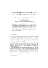
14 CHAPTER 1. INSTALLING WEBOTSSimple registrationIn order to proceed, launch <strong>Webot</strong>s on the computer on which you would like to install the licensefile. Go the Register menu item of the Help menu of <strong>Webot</strong>s and follow the instructions. If thiscomputer is connected to the Internet, everything will run smoothly, fill in the requested formand you will shortly receive the webots.key license file via e-mail. Otherwise, you will haveto fill in a form 2 on the website of Cyberbotics (see figure 1.1). You will then receive an e-mailcontaining the webots.key file corresponding to your license.Figure 1.1: <strong>Webot</strong>s registration pagePlease take care to properly fill in each field of this form. The Serial Number is the serial numberof your <strong>Webot</strong>s package which is printed the CD-ROM under the heading S/N:. The computerID is given by <strong>Webot</strong>s in the Register menu item of the Help menu.2 http://www.cyberbotics.com/registration/webots4.html
1.3. REGISTRATION PROCEDURE 15After completing this form, click on the Submit button. You will receive shortly thereafter ane-mail containing your personal license file webots.key which is needed to install a registeredcopy of <strong>Webot</strong>s as described below.Registering several computersIf you need to register several computers, it may be convenient to register all the computers inthe same webots.key license file. Hence this unique license file could be copied across all thecomputers needing a <strong>Webot</strong>s license.In order to proceed, just enter several computer IDs on the web form, corresponding to all thecomputers you want to register. The computer IDs have to be seperated by a simple space character.Copying the license fileOnce you received it by e-mail, just copy the webots.key license file into the resourcesdirectory of your <strong>Webot</strong>s installation.Under Linux, copy your personal webots.key file into the /usr/local/webots/server/resourcesdirectory where <strong>Webot</strong>s was just installed.Under Mac OS X, copy your personal webots.key file into the <strong>Webot</strong>s:resources directorywhere <strong>Webot</strong>s was just installed.Under Windows, copy your personal webots.key file into the C:\Program Files\<strong>Webot</strong>s\resourcesdirectory where <strong>Webot</strong>s was just installed.
16 CHAPTER 1. INSTALLING WEBOTS
Chapter 2Upgrading from <strong>Webot</strong>s 3If you have already worked with <strong>Webot</strong>s 3, your existing programs may need to be modified foruse with <strong>Webot</strong>s 4.2.1 Controller2.1.1 Controller includesThe include path of the device files is the same as in <strong>Webot</strong>s 3.2, i.e.:#include #include #include 2.1.2 Controller libraryThe name of the controller library to which you will link your executable files changed to ”Controller.dll”on Windows and ”libController.so” on Linux. It is not any more ”GtkController.dll”or ”libGtkController.so”. Please update your project files or make files appropriately.2.1.3 Basic data typeSince GTK+ and glib are not used any more, the data type coming from the glib are not recognizedany more. <strong>Webot</strong>s 4 uses the more standard C data types. Moreover, a couple of other<strong>Webot</strong>s specific data type have slightly changed to become more consistant with the rest of theAPI. Please replace the following data types in your programs:17
18 CHAPTER 2. UPGRADING FROM WEBOTS 32.1.4 Khepera<strong>Webot</strong>s 3 <strong>Webot</strong>s 4gchar charguchar unsigned charguint8 unsigned chargint8 chargint intguint unsigned intgint32 intguint32 unsigned intgint16 shortguint16 unsigned shortgfloat floatgdouble doublegpointer void *device tag DeviceTagnode ref NodeRefTable 2.1: Data types changes between <strong>Webot</strong>s 3 and <strong>Webot</strong>s 4If you developed controllers specifically for the Khepera robot, the khepera live functionshould be replaced by robot live. Moreover, the #include should be removed. Please check also that the model field of the DifferentialWheels nodecorresponding to the Khepera robot is ”Khepera” or ”Khepera II”, so that it will be automaticallyrecognized by <strong>Webot</strong>s as a Khepera controller for remote control and code upload.2.1.5 GTK+ GUIThe GTK+ graphical user interface is not any more integrated within the controller library.Hence, you are free to use any graphical user interface library, like wxWindows, GTK+, Motif,MFC, etc. To use for example GTK+, you have two options: (1) you can perform all thegraphical user interface operations inside a separate thread, or (2) you can setup the GUI in thesame thread and call repeatly the gtk main iteration do function inside the main loop. Anexample of using wxWindows as the GUI of a controller in provided in the wxgui controllersample.2.2 WorldVery few changes were introduce in the <strong>Webot</strong>s worlds that breaks the compatibility. However,since <strong>Webot</strong>s 4 uses a different collision detection engine, boundingObject made up of
2.2. WORLD 19Extrusion or IndexedFaceSet have to be changed to composite objects made up of Box,Sphere and / or Cylinder. A composite object is a Group node containing Transform nodesas children. These Transform nodes should contain the primitive shapes previously enumeratedand positioned appropriately.
20 CHAPTER 2. UPGRADING FROM WEBOTS 3
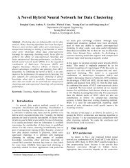
Chapter 3Getting Started with <strong>Webot</strong>sTo run a simulation in <strong>Webot</strong>s, you need two things:This chapter gives an overview of the basics of <strong>Webot</strong>s, including the display of the world in themain window and the structure of the .wbt file appearing in the scene tree window.Robot and Supervisor controllers will be explained in detail later on in this book.3.1 Launching <strong>Webot</strong>s3.1.1 On LinuxFrom an X terminal, type webots to launch the simulator. You should see the world windowappear on the screen (see figure 3.1).3.1.2 On Mac OS XOpen the directory in which you uncompressed the <strong>Webot</strong>s package and double-click on the<strong>Webot</strong>s icon. You should see the world window appear on the screen (see figure 3.1).3.1.3 On WindowsFrom the Start menu, go to the Program Files — Cyberbotics menu and click on the <strong>Webot</strong>s 4.0.9menu item. You should see the world window appear on the screen (see figure 3.1).21
22 CHAPTER 3. GETTING STARTED WITH WEBOTSFigure 3.1: <strong>Webot</strong>s main window3.2 Main Window: menus and buttonsThe main window allows you to display your virtual worlds and robots described in the .wbtfile. Four menus and a number of buttons are available.3.2.1 File menu and shortcutsThe New menu item opens a new default world representing a chessboard of 10 x 10 plates on asurface of 1 m x 1 m. The following button can be used as a shortcut:New
3.2. MAIN WINDOW: MENUS AND BUTTONS 23The File menu will also allow you to perform the standard file operations: Open..., Save and SaveAs..., respectively, to load, save and save with a new name the current world.The following buttons can be used as shortcuts:Open...SaveThe Revert item allows you to reload the most recently saved version of your .wbt file.The following button can be used as a shortcut:RevertThe Export VRML item allows you to save the .wbt file as a .wrl file, conforming to the VRML2.0 standard. Such a file can, in turn, be opened with any VRML 2.0 viewer. This is especiallyuseful for publishing a world created with <strong>Webot</strong>s on the Web.The Make Movie... item allows you to create a MPEG movie under Linux and Mac OS X or anAVI movie under Windows. As movies are created on a 30 frame per second basis, you shouldadapt the basic simulation step and the refresh display parameters in the general preferences toobtain a movie running at real time. Setting the basic simulation step to 32 ms and the refreshdisplay each 1 ms should produce movies runnig close to real time.The Screenshot... item allows you to take a screenshot of the current view in <strong>Webot</strong>s. It opens afile dialog to save the current view as a PNG image.The Preferences item pops up a window with the following panels:• General: The Startup mode allows you to choose the state of the simulation when <strong>Webot</strong>sis launched (stop, run, fast; see the Simulation menu).The Basic simulation step parameter defines the duration of the simulation step executedby <strong>Webot</strong>s. It is expressed in milliseconds. Setting this value to a high value willaccelerate the simulation, but will decrease the accuracy of the simulation, especially forphysics simulation and collision detection This value is also used when the Step button ispressed.The Refresh display parameter is multiplicated to the basic step value to define howfrequently the 3D display of the main window is refreshed in normal Run mode.• Rendering: this tab controls the 3D rendering in the simulation window.Checking the Display sensor rays check box displays the distance sensor rays of therobot(s) as red lines.Checking the Display lights check box displays the lights (PointLight in the worldso that they can be moved more accurately).
24 CHAPTER 3. GETTING STARTED WITH WEBOTS• Files and paths: The default .wbt world which is open when launching <strong>Webot</strong>s andthe user directory are defined here. The user directory should contain at least a worlds,controllers, and objects directories where <strong>Webot</strong>s will be looking for files.3.2.2 Edit menuThe Scene Tree Window item opens the window in which you can edit the world and the robot(s).A shortcut is available by double-clicking on a solid in the world. A solid is a physical object inthe world.3.2.3 Simulation menu and the simulation buttonsIn order to run a simulation a number of buttons are available corresponding to menu items foundunder the Simulation menu:Stop: interrupt Run or Fast modes.Step: execute one simulation basic step. The duration of such a step is defined in thepreferences of <strong>Webot</strong>s and can be adjusted to suit your needs.Run: execute simulation steps until the Stop mode is entered. In run mode, the 3D displayof the scene is refreshed every n basic step, where n is defined in the <strong>Webot</strong>s preferences.Fast: same as Run, except that no display is performed (<strong>Webot</strong>s PRO only). only.The Fast mode performs a very fast simulation mode suited for heavy computation (geneticalgorithms, vision, learning, etc.). However, as the world display is disabled during a Fast simulation,the scene in the world window remains blank until the Fast mode is stopped. This featureis available only with <strong>Webot</strong>s PRO.The World View / Robot View item allows you to switch between two different points of view:• World View: this view corresponds to a fixed camera standing in the world.• Robot View: this view corresponds to a mobile camera following a robot.The default view is the world view. If you want to switch to the Robot View, first select the robotyou want to follow (click on the pointer button then on the robot), and then choose Robot Viewin the Simulation menu. To return to the World View mode, reselect this item.A speedometer (see figure 3.2) allows you to observe the speed of the simulation on your computer.It is displayed in the bottom right hand side of the main window and indicates how fast the
3.2. MAIN WINDOW: MENUS AND BUTTONS 25simulation runs compared to real time. In other words, it represents the speed of the virtual time.If the value of the speedometer is 2, it means that your computer simulation is running twice asfast as the corresponding real robots would. This information is relevant both in Run mode andFast mode.Figure 3.2: SpeedometerThe basic simulation time step can be chosen from the preferences window. It is expressedin virtual time milliseconds. The value of this time step defines the duration of the time stepexecuted during the Step mode. This step is multiplicated by the refresh parameter to define howfrequently the display is refreshed. The refresh parameter can be changed from the preferenceswindow.In Run mode, with a time step of 64 ms and a fairly simple world displayed with the defaultwindow size, the speedometer will typically indicate approximately 0.5 on a Pentium II / 266Mhz without hardware acceleration and 12 on a Pentium III / 500 Mhz with an nVidia GeforceII MX graphics card.3.2.4 Help menuIn the Help menu, the About... item opens the About... window, displaying the license information.The Introduction item is a short introduction to <strong>Webot</strong>s (HTML file). You can access the User<strong>Guide</strong> and the Reference Manual with the User <strong>Guide</strong> and Reference Manual items (PDF files).The Web site of Cyberbotics item lets you visit our Web site.3.2.5 Navigation in the sceneThe view of the scene is generated by a virtual camera set in a given position and orientation.You can change this position and orientation to navigate in the scene using the mouse buttons.The x, y, z axes mentioned below correspond to the coordinate system of the camera; z is the axiscorresponding to the direction of the camera.• Rotate viewpoint: To rotate the camera around the x and y axis, you have to set the mousepointer in the 3D scene, press the left mouse button and drag the mouse:
26 CHAPTER 3. GETTING STARTED WITH WEBOTSif you clicked on a solid object, the rotation will be centered around the origin of the localcoordinate system of this object.if you clicked outside of any solid object, the rotation will be centered around the origin ofthe world coordinate system.• Translate viewpoint: To translate the camera in the x and y directions, you have to set themouse pointer in the 3D scene, press the right mouse button and drag the mouse.• Zoom / Tilt viewpoint: set the mouse pointer in the 3D scene, then:if you press both left and right mouse buttons (or the middle button) and drag the mousevertically, the camera will zoom in or out.if you press both left and right mouse buttons (or the middle button) and drag the mousehorizontally, the camera will rotate around its z axis (tilt movement).if you use the wheel of the mouse, the camera will zoom in or out.3.2.6 Moving a solid objectIn order to move an object, hold the shift key down while using the mouse.• Translation: Pressing the left mouse button while the shift key is pressed allows you todrag solid objects on the ground (xz plan).• Rotation: Pressing the right mouse button while the shift key is pressed rotates solid objects:a first click is necessary to select a solid object, then a second press-and-drag rotatesthe selected object around its y axis.• Lift: Pressing both left and right mouse buttons, the middle mouse button, or rolling themouse wheel while the shift key is pressed allows you to lift up or down the selected solidobject.3.2.7 Selecting a solid objectSimply clicking on a solid object allows you to select this object. Selecting a robot enables thechoice of Robot View in the simulation menu. Double-clicking on a solid object opens the scenetree window where the world and robots can be edited. The selected solid object appears selectedin the scene tree window as well.
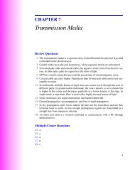
3.3. SCENE TREE WINDOW 273.3 Scene Tree WindowAs seen in the previous section, to access to the Scene Tree Window you can either choose SceneTree Window in the Edit menu, or click on the pointer button and double-click on a solid object.The scene tree contains all information necessary to describe the graphic representation and simulationof the 3D world. A world in <strong>Webot</strong>s includes one or more robots and their environment.The scene tree of <strong>Webot</strong>s is structured like a VRML file. It is composed of a list of nodes, eachcontaining fields. Fields can contain values (text string, numerical values) or nodes.Some nodes in <strong>Webot</strong>s are VRML nodes, partially or totally implemented, while others arespecific to <strong>Webot</strong>s. For instance the Solid node inherits from the Transform node of VRMLand can be selected and moved with the buttons in the World Window.This section describes the buttons of the Scene Tree Window, the VRML nodes, the <strong>Webot</strong>sspecific nodes and how to write a .wbt file in a text editor.Figure 3.3: Scene Tree Window3.3.1 Buttons of the Scene Tree WindowThe scene tree with the list of nodes appears on the left side of the window. Clicking on the + infront of a node or double-clicking on the node displays the fields inside the node, and similarly
28 CHAPTER 3. GETTING STARTED WITH WEBOTSexpands the fields. The field values can be defined on the top right side of the window. Fiveediting buttons are available on the bottom right side of the window:CutCopyPaste afterThese three buttons let you cut, copy and paste nodes and fields. However, you can’t performthese operations on the three first nodes of the tree (WorldInfo, Viewpoint and Background).These nodes are mandatory and don’t need to be duplicated. Similarly, you can’t copy theSupervisor node because only one supervisor is allowed. Please note that when you cut orcopy a robot node, like a DifferentialWheels or Supervisor node, the controller fieldof this node is reset to "void".Delete: This button allows you to delete a node. It appears only if a node is selected. If afield is selected, the Default Value button appears instead.Default Value: You can click on this button to reset the default value(s) of a field. A fieldwith values must be selected in order to perform this button. If a node is selected, the Deletebutton replaces it.Transform: This button allows you to transform a node into another one.Insert after: With this button, you can insert a node after the one currently selected. Thisnew node contains fields with default values, which you can of course modify to suit your needs.This button also allows you to add a node to a children field. In all cases, the software onlypermits you to insert a coherent node.Insert Node: Use this to insert a node into a field whose value is a node. You can insertonly a coherent node.Export Node: Use this button to export a node into a file. Usually, nodes are saved in yourobjects directory. Such saved nodes can then be reused in other worlds.Import Node: Use this button to import a previously saved node into the scene tree. Usually,saved nodes are located in the <strong>Webot</strong>s objects directory or in your own objects directory.The <strong>Webot</strong>s objects directory already contains a few nodes that can be easily imported.
3.3. SCENE TREE WINDOW 293.3.2 VRML nodesA number of VRML 2.0 nodes are partially or completely supported in <strong>Webot</strong>s.The exact features of VRML 2.0 are the subject of a standard managed by the InternationalStandards Organization (ISO/IEC 14772-1:1997).You can find the complete specifications on the official VRML Web site: \texttt{http://www.vrml.org}.The VRML nodes supported in <strong>Webot</strong>s are the following:• Appearance• Background• Box• Color• Cone• Coordinate• Cylinder• DirectionalLight• ElevationGrid• Fog• Group• ImageTexture• IndexedFaceSet• IndexedLineSet• Material• PointLight• Shape• Sphere• Switch• TextureCoordinate
30 CHAPTER 3. GETTING STARTED WITH WEBOTS• TextureTransform• Transform• Viewpoint• WorldInfoThe Reference Manual gives a comprehensive list of nodes with associated fields.3.3.3 <strong>Webot</strong>s specific nodesIn order to implement powerful simulations including mobile robots with two-wheel differentialsteerings, a number of nodes specific to <strong>Webot</strong>s have been added to the VRML set of nodes.VRML uses a hierarchical structure for nodes. For example, the Transform node inherits fromthe Group node, such that, like the Group node, the Transform node has a children field,but it also adds three additional fields: translation, rotation and scale.In the same way, <strong>Webot</strong>s introduces new nodes which inherit from the VRML Transform node,principally the Solid node. Other <strong>Webot</strong>s nodes (DifferentialWheels, DistanceSensor,Camera, etc.) inherit from this Solid node.The Reference Manual gives a complete description of all <strong>Webot</strong>s nodes and their respectivefields.3.3.4 Principle of the collision detectionThe collision detection engine is able to detect a collision between two Solid nodes. It calculatesthe intersection between the bounding objects of the solids. A bounding object (described in theboundingObject field of the Solid node) is a geometric shape or a group of geometric shapeswhich bounds the solid. If the boundingObject field is NULL, then no collision detection isperformed for this Solid node. list of children of the Solid node are used to compute thebounding object.The collision detection is mainly of use between a robot DifferentialWheels node) and anobstacle (Solid node), and between two robots. Two Solid nodes can never inter-penetrateeach other; their movement is stopped just before the collision.Example: a solid with a bounding box different from its list of children.Let us consider the Khepera robot model. It is not exactly a Solid node, but the principle for theboundingObject is the same. Open the khepera.wbt file and look at the boundingObjectfield of the DifferentialWheels node. The bounding object is a cylinder which has beentransformed. See figure 3.4.
3.4. CITING WEBOTS 31Figure 3.4: The bounding box of the Khepera robot3.3.5 Writing a <strong>Webot</strong>s file in a text editorIt is possible to write a <strong>Webot</strong>s world file (.wbt) using a text editor. A world file contains aheader, nodes containing fields and values. Note that only a few VRML nodes are implemented,and that there are nodes specific to <strong>Webot</strong>s. Moreover, comments can only be written in the DEF,and not like in a VRML file.The <strong>Webot</strong>s header is:#VRML_SIM V4.0 utf8After this header, you can directly write your nodes. The three nodes WorldInfo, Viewpointand Background are mandatory.Note: we recommend that you write your file using the tree editor. However it may be easier tomake some particular modifications using a text editor (like using the search and replace featureof a text editor).3.4 Citing <strong>Webot</strong>sWhen writing a scientific paper, or describing your project involving <strong>Webot</strong>s on a web site, itis always appreciated to make a correct reference to <strong>Webot</strong>s, mentionning Cyberbotics web site
32 CHAPTER 3. GETTING STARTED WITH WEBOTSexplicitely. In order to help you in such a task, we provide here some citation examples, includinga BibTex entry that you can freely reuse in your own documents:This project uses <strong>Webot</strong>s 1 , a commercial mobile robot simulation software developed by CyberboticsLtd.This project uses <strong>Webot</strong>s (http://www.cyberbotics.com), a commercial mobile robot simulationsoftware developed by Cyberbotics Ltd.The BibTex reference entry may look odd, as it is very different from a standard paper citationand we want the specified fields to appear in the normal plain citation mode of LaTeX.@Misc{<strong>Webot</strong>s,author={<strong>Webot</strong>s},title={http://www.cyberbotics.com},note={Commercial Mobile Robot Simulation Software},editor={Cyberbotics Ltd.},url={http://www.cyberbotics.com}}Once compiled with LaTeX, it should display as follow:References[1] <strong>Webot</strong>s. http://www.cyberbotics.com. Commercial Mobile Robot Simulation Software.1 http://www.cyberbotics.com
Chapter 4Tutorial: Modeling and simulating yourrobotThe aim of this chapter is to give you several examples of robots, worlds and controllers. The firstworld is very simple, nevertheless it introduces the construction of any basic robot, and explainshow to program a controller. The second example will show you how to model a camera on thissimple robot. The third example will show you how to build a virtual Pioneer 2 TM robot fromActivMedia Robotics. The fourth part will explain how to work with robots from K-Team.4.1 My first world: kiki.wbtAs a first introduction, we are going to simulate a very simple robot made up of a box, two wheelsand two infra-red sensors (see figure 4.1), controlled by a program inspired by a Braitenbergalgorithm, in a simple environment surrounded by a wall.4.1.1 EnvironmentWe just want to have a simple world with a surrounding wall. We will represent this wall usingan Extrusion node. The coordinates of the wall are shown in figure 4.2.First, go to the File menu, New item to open a new world. Then open the Scene Tree Window(from the Edit menu). We are going to change the lighting of the scene:1. Select the PointLight node, and click on the + just in front of it. You can now see thedifferent fields of the PointLight node. Select ambientIntensity and enter 0.6 as avalue, then select intensity and enter 0.8, then select location and enter 0.5 0.5 0.5as values. Press return.33
34 CHAPTER 4. TUTORIAL: MODELING AND SIMULATING YOUR ROBOTIR sensorsFigure 4.1: The kiki robotwheels2. Select the PointLight node, copy and paste it. In this new PointLight node, type -0.50.5 0.5 in the location field.3. Repeat this paste twice again with -0.5 0.5 -0.5 in the location field of the third PointLightnode, and 0.5 0.5 -0.5 in the location field of the fourth and last PointLight node.4. The scene is now better lit.Secondly, let us create the wall:1. Select the last Transform node and click on the insert after button.2. Choose a Solid node.3. Type ”wall” in the name field.4. Select the children field and Insert after a Shape node.5. Insert a new Appearance node in the appearance field. Insert a new Material nodein the material field of the Appearance node. Select the diffuseColor field of theMaterial node and choose a color to define the color of the wall.6. Now insert an Extrusion node in the geometry field of the Shape.7. Set convex to FALSE. Then, set the wall corner coordinates in the crossSection field.You will have to re-enter the first point (0) at the last position (10) to complete the last faceof the extrusion.8. In the spine field, write that the wall ranges between 0 and 0.1 along the y axis.
4.1. MY FIRST WORLD: KIKI.WBT 35z7841 23x(x,z) coordinates:0 (−0.489, −0.5)1 (−0.489, −0.49)2 (0.49, −0.49)3 (0.49, 0.49)4 (−0.49, 0.49)5 (−0.49, −0.5)6 (−0.5, −0.5)7 (−0.5, 0.5)8 (0.5, 0.5)9 (0.5, −0.5)6509Figure 4.2: The kiki world9. As we want our robot to detect the wall, we have to fill in the boundingObject field. Thebounding object can have exactly the same shape as the wall, so insert a DEF at the level ofgeometry Extrusion: WALL. Then, in the boundingObject field, insert USE WALL.10. Close the tree editor, save your file and look at the result.The wall in the tree editor is represented in figure 4.3, while the same wall in the world editor isvisible in figure 4.4
36 CHAPTER 4. TUTORIAL: MODELING AND SIMULATING YOUR ROBOTFigure 4.3: The wall in the tree editorFigure 4.4: The wall in the world window
4.1. MY FIRST WORLD: KIKI.WBT 374.1.2 RobotThe aim of this subsection is to model the kiki robot. This robot is made up of a DifferentialWheelsnode, in which we find several children: a Transform node for the body, two Solid nodes forthe wheels, two DistanceSensor nodes for the infra-red sensors and a Shape node with atexture.The origin and the axis of the coordinate system of the robot and its dimensions are shown infigure 4.5.FRONT VIEWyLEFT SIDE VIEWyxz0.080.080.080.020.05Ø 0.050.01Figure 4.5: Coordinate system and dimensions of the kiki robotTo model the body of the robot:1. Open the scene tree window.2. Select the last Solid node.3. Insert after a DifferentialWheels node, give it a name: ”kiki”.
38 CHAPTER 4. TUTORIAL: MODELING AND SIMULATING YOUR ROBOT4. In the children field, first introduce a Transform node that will contain a box shape.In the new children field, insert after a Shape node. Choose a color, as describedpreviously. In the geometry field, insert a Box node. Set the dimension of the box to[0.08 0.08 0.08]. Now set the translation values to [ 0 0.06 0 ] in the Transform node(see figure 4.6)To model the left wheel of the robot:Figure 4.6: Body of the kiki robot: a box1. Select the previous Transform and insert after a Solid node in order to model the leftwheel. Type ”left wheel” in the name field, so that this Solid node is recognized as theleft wheel of the robot and will rotate according to the motor command.2. The axis of rotation of the wheel is x. The wheel will be made of a Cylinder rotatedof pi/2 radians around the z axis. To obtain proper movement of the wheel, you must payattention not to confuse these two rotations. consequently, you must add a Transformnode to the children of the Solid node.3. After adding this Transform node, introduce a Shape with a Cylinder in its geometryfield. The dimensions of the cylinder are 0.01 for the height and 0.025 for the radius.Set the rotation to [ 0 0 1 1.57 ]. Pay attention to the sign of the rotation; if it is false,the wheel will turn in the wrong direction.4. In the Solid node, set the translation to [-0.045 0.025 0] to position the left wheel, and setthe rotation of the wheel around the x axis: [1 0 0 0].
4.1. MY FIRST WORLD: KIKI.WBT 395. Give a DEF name to your Transform: WHEEL; notice that you positioned the wheel intranslation at the level of the Solid node, so that you can reuse the WHEEL Transformfor the right wheel.6. Close the tree window, look at the world and save it. Use the navigation buttons to changethe point of view.To model the right wheel of the robot:1. Select the left wheel Solid node and insert after another Solid node. Type ”right wheel”in the name field. Set the translation to [0.045 0.025 0] and the rotation to [1 0 0 0].2. In the children, insert after USE WHEEL. Press Return, close the tree window and savethe file. You can examine your robot in the world editor, move it and zoom in on it.The robot and its two wheels are shown in figure 4.7 and figure 4.8.The two infra-red sensors are defined as two cylinders on the front of the robot body. Theirdiameter is 0.016 m and their height is 0.004 m. You must position these sensors properly so thatthe sensor rays point in the right direction, toward the front of the robot.1. In the children of the DifferentialWheels node, insert after a DistanceSensornode.2. Type the name ”ir0”. It will be used by the controller program.3. Now, we will attach a cylinder shape to this sensor. In the children of the DistanceSensornode, insert after a Transform node. Give a DEF name to it: INFRARED, which you willuse for the second IR sensor.4. In the children of the Transform node, insert after a Shape node. Choose an appearanceand insert a Cylinder in the geometry field. Type 0.004 for the height and 0.08 forthe radius.5. Set the rotation for the Transform node to [0 0 1 1.57] to adjust the orientation of thecylinder.6. In the DistanceSensor node, set the translation to position the sensor and its ray: [0.020.08 -0.042]. In the File menu, Preferences, Rendering, check the Display sensor rays box.In order to have the ray directed toward the front of the robot, you must set the rotation to[0 1 0 1.57].7. In the DistanceSensor node, you must introduce some values of distance measurementsof the sensors to the lookupTable field, according to figure 4.9. These values are:
40 CHAPTER 4. TUTORIAL: MODELING AND SIMULATING YOUR ROBOTFigure 4.7: Wheels of the kiki robotlookupTable [ 0 1024 0,0.05 1024 0,0.15 0 0 ]8. To model the second IR sensor, select the DistanceSensor node and insert after a newDistanceSensor node. Type ”ir1” as a name. Set its translation to [-0.02 0.08 -0.042]and its rotation to [0 1 0 1.57]. In the children, insert after USE INFRARED. In thelookupTable field, type the same values as shown above.The robot and its two sensors are shown in figure 4.10 and figure 4.11.Note: a texture can only be mapped on an IndexedFaceSet shape. The texCoord and texCoordIndexentries must be filled. The image used as a texture must be a .png or a .jpg file, and its size
4.1. MY FIRST WORLD: KIKI.WBT 41Figure 4.8: Body and wheels of the kiki robotmust be (2ˆn) * (2ˆn) pixels (for example 8x8, 16x16, 32x32, 64x64, 128x128 or 256x256 pixels).Transparent images are not allowed in <strong>Webot</strong>s. Moreover, PNG images should use either the 24or 32 bit per pixel mode (lower bpp or gray levels are not supported). Beware of the maximumsize of texture images depending on the 3D graphics board you have: some old 3D graphicsboards are limited to 256x256 texture images while more powerful ones will accept 2048x2048texture images.To paste a texture on the face of the robot:1. Select the last DistanceSensor node and insert after a Shape node.2. In the appearance field, insert an Appearance node. In the texture field of this node,insert an ImageTexture node with the following URL: "kiki/kiki.png".3. In the geometry field, insert an IndexedFaceSet node, with a Coordinate node inthe coord field. Type the coordinates of the points in the point field.[ 0.015 0.05 -0.041,0.015 0.03 -0.041,-0.015 0.03 -0.041,-0.015 0.05 -0.041 ]
42 CHAPTER 4. TUTORIAL: MODELING AND SIMULATING YOUR ROBOTMeasuredvalue102400.05 0.15Distance tothe wallFigure 4.9: Distance measurements of the kiki sensors.and insert after the coordIndex field the values 0, 1, 2, 3, -1.4. In the texCoord field, insert a TexureCoordinate node. In the point field, enter thecoordinates of the texture:[ 0 01 01 10 1 ]and in the texCoordIndex field, type 3, 0, 1, 2.5. The texture values are shown in figure 4.12.To finish with the DifferentialWheels node, you must fill in a few more fields:1. In the controller field, type the name ”simple”. It will be used by the controller program.2. The boundingObject field can contain a Transform node with a Box, as a box asa bounding object for collision detection is sufficient to bound the kiki robot. Insert aTransform node in the boundingObject field, with the translation set to [0 0.05-0.002] and a Box node in its children. Set the dimension of the Box to [0.1 0.1 0.084].3. In the axleLength field, enter the length of the axle between the two wheels: 0.09 (accordingto figure 4.5).4. In the wheelRadius field, enter the radius of the wheels: 0.025.5. Values for other fields are shown in figure 4.13 and the finished robot in its world is shownin figure 4.14.
4.1. MY FIRST WORLD: KIKI.WBT 43Figure 4.10: The DistanceSensor nodes of the kiki robot
44 CHAPTER 4. TUTORIAL: MODELING AND SIMULATING YOUR ROBOTFigure 4.11: The kiki robot and its sensors
4.1. MY FIRST WORLD: KIKI.WBT 45Figure 4.12: Defining the texture of the kiki robot
46 CHAPTER 4. TUTORIAL: MODELING AND SIMULATING YOUR ROBOTFigure 4.13: The other fields of the DifferentialWheels nodeFigure 4.14: The kiki robot in its world
4.1. MY FIRST WORLD: KIKI.WBT 47The kiki.wbt is included in the <strong>Webot</strong>s distribution, in the worlds directory.4.1.3 A simple controllerThis first controller is very simple and thus named simple. The controller program simply readsthe sensor values and sets the two motors speeds, in such a way that kiki avoids the obstacles.Below is the source code for the simple.c controller:#include #include #include #define SPEED 100static DeviceTag ir0,ir1;void reset(void) {ir0 = robot_get_device("ir0");ir1 = robot_get_device("ir1");// printf("ir0=134531395 ir1=1108542220\n",ir0,ir1);}int main() {short left_speed,right_speed;unsigned short ir0_value,ir1_value;robot_live(reset);distance_sensor_enable(ir0,64);distance_sensor_enable(ir1,64);for(;;) { /* The robot never dies! */ir0_value = distance_sensor_get_value(ir0);ir1_value = distance_sensor_get_value(ir1);if (ir1_value>200) {left_speed = -20;right_speed = 20;} else if (ir0_value>200) {left_speed = 20;right_speed = -20;} else {left_speed =SPEED;right_speed=SPEED;}/* Set the motor speeds */differential_wheels_set_speed(left_speed,right_speed);
48 CHAPTER 4. TUTORIAL: MODELING AND SIMULATING YOUR ROBOTrobot_step(64); /* run one step */}return 0;4.2 My second world: a kiki robot with a cameraThe camera to be modeled is a color 2D camera, with an image 80 pixels wide and 60 pixelshigh, and a field of view of 60 degrees (1.047 radians).We can model the camera shape as a cylinder, on the top of the kiki robot at the front. Thedimensions of the cylinder are 0.01 for the radius and 0.03 for the height. See figure 4.15.Figure 4.15: The kiki robot with a cameraTry modeling this camera. The kiki camera.wbt file is included in the <strong>Webot</strong>s distribution, inthe worlds directory, in case you need any help.A controller program for this robot, named camera is also included in the <strong>Webot</strong>s distribution,in the controllers directory.
4.3. MY THIRD WORLD: PIONEER2.WBT 494.3 My third world: pioneer2.wbtWe are now going to model and simulate a commercial robot from ActivMedia Robotics: Pioneer2-DX TM , as shown on the ActivMedia Web site: http://www.activrobots.com. First, you mustmodel the robots environment. Then, you can model a Pioneer 2 TM robot with 16 sonars andsimulate it with a controller.Please refer to the worlds/pioneer2.wbt and controllers/pioneer2 files for the worldand controller details.4.3.1 EnvironmentThe environment consists of:• a chessboard: a Solid node with an ElevationGrid node.• a wall around the chessboard: Solid node with an Extrusion node.• a wall inside the world: a Solid node with an Extrusion node.This environment is shown in figure 4.16.4.3.2 Robot with 16 sonarsThe robot (a DifferentialWheels node) is made up of six main parts:1. the body: an Extrusion node.2. a top plate: an Extrusion node.3. two wheels: two Cylinder nodes.4. a rear wheel: a Cylinder node.5. front an rear sensor supports: two Extrusion nodes.6. sixteen sonars: sixteen DistanceSensor nodes.The Pioneer 2 DX TM robot is depicted in figure 4.17.Open the tree editor and add a DifferentialWheels node. Insert in the children field:1. for the body: a Shape node with a geometry Extrusion. See figure 4.18 for the coordinatesof the Extrusion.
50 CHAPTER 4. TUTORIAL: MODELING AND SIMULATING YOUR ROBOTFigure 4.16: The walls of the Pioneer 2 TM robot world2. for the top plate: a Shape node with a geometry Extrusion. See figure 4.19 for thecoordinates of the Extrusion.3. for the two wheels: two Solid nodes. Each Solid node children contains a Transformnode, which itself contains a Shape node with a geometry Cylinder. Each Solidnode has a name: ”left wheel” and ”right wheel”. See figure 4.20 for the wheels dimensions.4. for the rear wheel: a Transform node containing a Shape node with a geometry Cylinder, as shown in figure 4.215. for the sonar supports: two Shape nodes with a geometry Extrusion. See figure 4.22for the Extrusion coordinates.6. for the 16 sonars: 16 DistanceSensor nodes. Each DistanceSensor node containsa Transform node. The Transform node has a Shape node containing a geometryCylinder. See figure 4.23 and the text below for more explanation.Modeling the sonars:The principle is the same as for the kiki robot. The sonars are cylinders with a radius of 0.0175and a height of 0.002. There are 16 sonars, 8 on the front of the robot and 8 on the rear of the
4.3. MY THIRD WORLD: PIONEER2.WBT 51Figure 4.17: The Pioneer 2 DX TM robotrobot (see figure 4.23). The angles between the sonars and the initial position of the DEF SONARTransform are shown in figure 4.24. A DEF SONAR Transform contains a Cylinder node ina Shape node with a rotation around the z axis. This DEF SONAR Transform must be rotatedand translated to become the sensors FL1, RR4, etc.
52 CHAPTER 4. TUTORIAL: MODELING AND SIMULATING YOUR ROBOT21zBACK07Coordinates of the crossSection field ofthe extrusion node:0: x=−0.1, z=0.2151: x=0.1, z=0.2152: x=0.135, z=0.1853: x=0.135, z=−0.0954: x=0.08, z=−0.115: x=−0.08, z=−0.116: x=−0.135, z=−0.0957: x=−0.135, z=0.185x0.059 < y
4.3. MY THIRD WORLD: PIONEER2.WBT 53yRadius of the wheels: 0.0825Depth of the wheels: 0.037RIGHTWHEELZLEFTWHEELx0.3206Figure 4.20: Wheels of the Pioneer 2 TM robotyxRadius of the wheel: 0.0325Width of the wheel: 0.0240.2147REARWHEELFigure 4.21: Rear wheel of the Pioneer 2 TM robotz
54 CHAPTER 4. TUTORIAL: MODELING AND SIMULATING YOUR ROBOT78654zREAR SONARSUPPORT3201Coordinates of the crossSection field of theExtrusion node "Rear sonar support":0: x=−0.136 z=0.1351: x=−0.136 z=0.1852: x=−0.101 z=0.2233: x=−0.054 z=0.2484: x=0 z=0.2585: x=0.054 z=0.2486: x=0.101 z=0.2237: x=0.136 z=0.1858: x=0.136 z=0.135x012FRONT SONARSUPPORT345687Coordinates of the crossSection field of theExtrusion node "Front sonar support":0: x=0.136 z=−0.0461: x=0.136 z=−0.0962: x=0.101 z=−0.1343: x=0.054 z=−0.1594: x=0 z=−0.1685: x=−0.054 z=−0.1596: x=−0.101 z=−0.1347: x=−0.136 z=−0.0968: x=−0.136 z=−0.0460.184 < y < 0.234Figure 4.22: Sonar supports of the Pioneer 2 TM robotzRR4RR3RR2RR1RL1REAR SONARSUPPORTRL2RL3RL4RR: Rear Right SonarRL: Rear Left SonarFR: Front Right SonarFL: Front Left SonarxFR4FR3FRONT SONARSUPPORTFL4FL3FR2FL2FR1FL1Figure 4.23: Sonars location on the Pioneer 2 TM robot
4.3. MY THIRD WORLD: PIONEER2.WBT 55zSonar rayDEF SONAR TransformxFR4FR340FR26080 degreesFR1Figure 4.24: Angles between the Pioneer 2 TM sonar sensors
56 CHAPTER 4. TUTORIAL: MODELING AND SIMULATING YOUR ROBOTEach sonar is modeled as a DistanceSensor node, in which can be found a rotation aroundthe y axis, a translation, and a USE SONAR Transform, with a name (FL1, RR4, ...) to be usedby the controller.Sonar name translation rotationFL1 -0.027 0.209 -0.164 0 1 0 1.745FL2 -0.077 0.209 -0.147 0 1 0 2.094FL3 -0.118 0.209 -0.11 0 1 0 2.443FL4 -0.136 0.209 -0.071 0 1 0 3.14FR1 0.027 0.209 -0.164 0 1 0 1.396FR2 0.077 0.209 -0.147 0 1 0 1.047FR3 0.118 0.209 -0.116 0 1 0 0.698FR4 0.136 0.209 -0.071 0 1 0 0RL1 -0.027 0.209 0.253 0 1 0 -1.745RL2 -0.077 0.209 0.236 0 1 0 -2.094RL3 -0.118 0.209 0.205 0 1 0 -2.443RL4 -0.136 0.209 0.160 0 1 0 -3.14RR1 0.027 0.209 0.253 0 1 0 -1.396RR2 0.077 0.209 0.236 0 1 0 -1.047RR3 0.118 0.209 0.205 0 1 0 -0.698RR4 0.136 0.209 0.160 0 1 0 0Table 4.1: Translation and rotation of the Pioneer 2 TM DEF SONAR TransformsTo finish modeling the Pioneer 2 TM robot, fill in the remaining fields of the DifferentialWheelsnode as shown in figure 4.25.4.3.3 ControllerThe controller of the Pioneer 2 TM robot is fairly complex. It implements a Braitenberg controllerto avoid obstacles using its sensors. An activation matrix was determined by trial and error tocompute the motor commands from the sensor measurements. However, since the structure ofthe Pioneer 2 TM is not circular some tricks are used, such as making the robot go backward inorder to rotate safely when avoiding obstacles. The source code of this controller is a goodprogramming example. The name of this controller is pioneer2.
4.3. MY THIRD WORLD: PIONEER2.WBT 57Figure 4.25: Some fields of the Pioneer 2 TM DifferentialWheels node
58 CHAPTER 4. TUTORIAL: MODELING AND SIMULATING YOUR ROBOT
Chapter 5Robot and Supervisor Controllers5.1 OverviewA robot controller is a program usually written in C, C++ or Java used to control one robot. Asupervisor controller is a program usually written in C or C++ used to control a world and itsrobots.5.2 Setting Up a New ControllerIn order to develop a new controller, you must first create a controllers directory in your userdirectory to contain all your robot and supervisor controller directories. Each robot or supervisorcontroller directory contains all the files necessary to develop and run a controller. In orderto tell <strong>Webot</strong>s where your controllers are, you must set up your user directory in the <strong>Webot</strong>spreferences. <strong>Webot</strong>s will first search for a controllers directory in your user directory, and ifit doesn’t find, it will then look in its own controllers directory. Now, in your newly createdcontrollers directory, you must create a controller subdirectory, let’s call it simple. Insidesimple, several files must be created:• a number of C source files, like simple.c which will contain your code.• a Makefile which can be copied (or inspired) from the <strong>Webot</strong>s controllers directories.Note that Windows users have several alternatives to the Makefile: They canuse a Dev-C++ project or a Microsoft Visual C++ project, as exemplified in the <strong>Webot</strong>scontrollers/braiten directory.You can compile your program by typing make in the directory of your controller.As an introduction, it is recommended that you copy the simple controller directory from the<strong>Webot</strong>s controllers to your own controllers directory and then try to compile it.59
60 CHAPTER 5. ROBOT AND SUPERVISOR CONTROLLERSUnder Windows, if you use make and would like that your controller program opens up a DOSconsole to display printf messages, add the following line in your Makefile:DOS_CONSOLE=15.3 <strong>Webot</strong>s Execution Scheme5.3.1 From the controller’s point of viewEach robot controller program is built in the same manner. An initialization with the functionrobot live is necessary before starting the robot. A callback function is provided to therobot live function in order to identify the devices of the robot (see section 5.4). Then an endlessloop (usually implemented as a for(;;) { } statement) runs the controller continuouslyuntil the simulator decides to terminate it. This endless loop must contain at least one call tothe robot step function which asks the simulator to advance the simulation time a given numberof milliseconds, thus advancing the simulation. Before calling robot step, the controllercan enable sensor reading and set actuator commands. Sensor data can be read immediately aftercalling robot step. Then you can perform your calculations to determine the appropriateactuator commands for the next step.5.3.2 From the point of view of <strong>Webot</strong>s<strong>Webot</strong>s receives controller requests from possibly several robots controllers. Each request isdivided into two parts: an actuator command part which takes place immediately, and a sensormeasuring part which is scheduled to take place after a given number of milliseconds (as definedby the parameter of the step function). Each request is queued in the scheduler and the simulatoradvances the simulation time as soon as it receives new requests.5.3.3 Synchronous versus Asynchronous controllersEach robot (DifferentialWheels or Supervisor) may be either synchronous or asynchronous.<strong>Webot</strong>s waits for the requests of synchronous robots before it advances the simulation time; itdoesn’t wait for asynchronous ones. Hence an asynchronous robot may be late (if the controlleris computationally expensive, or runs on a remote computer with a slow network connection).In this case, the actuator command occurs later than expected. If the controller is very late, thesensor measurement may also occur later than expected. However, this delay can be verified bythe robot controller by reading the return value of the robot step function (see the ReferenceManual for more details). In this way the controller can adapt its behavior and compensate.
5.4. READING SENSOR INFORMATION 61Synchronous controllers are recommended for robust control, while asynchronous controllersare recommended for running robot competitions where computer resources are limited, or fornetworked simulations involving several robots dispatched over a computer network with anunpredictable delay (like the Internet).5.4 Reading Sensor InformationTo obtain sensor information, the sensor must be:1. identified: this is performed by the robot get device function which returns a handlerto the sensor from its name. This needs to be done only once in the reset callback function,which is provided as an argument to the robot live function. The only exception to thisrule concerns the root device of a robot (DifferentialWheels or CustomRobot node) whichdoesn’t need to be identified, because it is the default device (it always exists and there isonly one of such device in each robot).2. enabled: this is performed by the appropriate enable function specific to each sensor (seedistance sensor enable for example). It can be done once, before the endless loop,or several times inside the endless loop if you decide to disable and enable the sensorsfrom time to time to save computation time.3. run: this is performed by the robot step function inside the endless loop.4. read: finally, you can read the sensor value using a sensor specific function call, likedistance sensor get value inside the endless loop.5.5 Controlling ActuatorsActuators are easier to handle than sensors. They don’t need to be enabled. To control an actuator,it must be:1. identified: this is performed by the robot get device function which returns a handlerto the actuator from its name. This needs to be done only once in the reset callback function,which is provided as an argument to the robot live function. As with sensors, theonly exception to this rule concerns the root device of a robot.2. set: this is performed by the appropriate set function specific to each actuator (see differential wheelsfor an example). It is usually called in the endless loop with different computed values ateach step.3. run: this is done by the robot step function inside the endless loop.
62 CHAPTER 5. ROBOT AND SUPERVISOR CONTROLLERS5.6 Going further with the Supervisor ControllerThe supervisor can be seen as a super robot. It is able to do everything a robot can do, and more.This feature is especially useful for sending messages to and receiving messages from robots,using the Receiver and Emitter nodes. Additionally, it can do many more interesting things.A supervisor can move or rotate any object in the scene, including the Viewpoint, change thecolor of objects, and switch lights on and off. It can also track the coordinate of any object whichcan be very useful for recording the trajectory of a robot. As with any C program, a supervisorcan write this data to a file. Finally, the supervisor can also take a snapshot of the current sceneand save it as a jpeg or PNG image. This can be used to create a ”webcam” showing the currentsimulation in real-time on the Web!
Chapter 6Tutorial: Using the Khepera TM robotThe goal of this chapter is to explain you how to use <strong>Webot</strong>s with your Khepera robot. Kheperais a mini mobile robot developed by K-Team SA, Switzerland (www.k-team.com).<strong>Webot</strong>s can use the serial port of your computer to communicate with the Khepera robot.6.1 Hardware configuration1. Configure your Khepera robot in mode 1, for serial communication protocol at 9600 baudas described in figure 6.1.2. Plug the serial connection cable between your Khepera robot and the Khepera interface.3. Plug the Khepera Interface into a serial port of your computer (either COM1 or COM2, atyour convenience).4. Check the the Khepera robot power switch is OFF and plug the power supply to the KheperaInterface.Note: Linux and Mac OS X users may want to redefine the COM1, COM2, COM3 and COM4 portsby setting WEBOTS COM1, WEBOTS COM2 WEBOTS COM3 and/or WEBOTS COM4 environment variablesto point to the appropriate /dev device files.On Linux, if these environment variables are not set, <strong>Webot</strong>s will use respectively /dev/ttyS0,/dev/ttyS1, /dev/ttyS2 and /dev/ttyS3 for COM1, COM2 COM3 and COM4 (note the -1difference). For example, if your laptop running Linux has no serial port, you may want touse a USB-RS232 converter, in which case it may be useful to type something like: exportWEBOTS COM1 /dev/ttyUSB0 to allow <strong>Webot</strong>s to communicate with the Khepera through theUSB port.63
64 CHAPTER 6. TUTORIAL: USING THE KHEPERA TM ROBOTserial portTop ViewledsA C E8 06 24mode selectorset to 1Figure 6.1: Khepera II mode selectionOn Mac OS X, only COM1 has a default value which is set to "/dev/tty.USB Serial", correspondingto the default USB to serial converter (like the one installed by the USB232-P9 converters).Other USB to serial converters may require that you define the WEBOTS COM1 environmentvariable to match their specific value. For example, the KeySpan USB to serial converter willneed that you define WEBOTS COM1 as "/dev/tty.USA28X1213P1.1". Please consult thedocumentation of your USB serial adapter to know the exact file name to be defined.That’s it. Your system is operational: you will now be able to simulate, remote control andtransfer controllers to your Khepera robot.6.2 Running the simulationLaunch <strong>Webot</strong>s: on Windows, double click on the lady bug icon, on Linux, type webots in aterminal. Go to the File Open menu item and open the file named khepera.wbt, which containsa model of a Khepera robot (see figure 6.2) associated with a Khepera controller (see figure 6.3).If the Khepera controller window do not show up, press the Step button in the main window of<strong>Webot</strong>s.You can navigate in the scene using the mouse pointer. To rotate the scene, click on the leftbutton and drag the mouse. To translate the scene, use the right button. To zoom and tilt, use themiddle button. You may also use the mouse wheel to zoom in or out.Using these controls, try to find a good view of the Khepera robot. You have probably noticedthat clicking on an object in the scene would select it. Select the Khepera robot and choose the
6.2. RUNNING THE SIMULATION 65Figure 6.2: Khepera example worldSimulation Robot View menu item. This way, the camera will follow the robot moves. Then,click on the Run button to start up the simulation. You will see the robot moving, while avoidingobstacles.To visualize the range of the infra red distance sensors, go to the File Preferences... menu item topop up the Preferences window. Then, check the Display sensor rays check box in the Renderingtab.In the controller windows, the values of the infra-red distance sensors are displayed in blue,while the light measurement values are displayed in light green. You can also observe the speedof each motor, displayed in red and the incremental encoder values displayed in dark green (seefigure 6.3).
66 CHAPTER 6. TUTORIAL: USING THE KHEPERA TM ROBOT6.3 Understanding the model6.3.1 The 3D sceneFigure 6.3: Khepera ControlsIn order to better understand what is going on with this simulation, let’s take a closer look at thescene structure. Double click on an object in the scene, or select the Edit Scene Tree Window toopen the scene tree window. If you double clicked on an object, you will see that object selectedin the scene tree (see figure 6.4). Clicking on the little cross icon of an object name in the scenetree, will expand that object, displaying its properties.We will not describe in details the <strong>Webot</strong>s scene structure in this chapter. It is build as anextension of the VRML97 standard. For a more complete description, please refer to the <strong>Webot</strong>suser guide and reference manuals. However, let’s have a first overview.You can see that the scene contains several objects, which we call nodes. You can play aroundwith the nodes, expanding them to look into their fields, and possibly change some values. TheWorldInfo node contains some text description about the world. The Viewpoint node definesthe camera from which the scene is viewed. The Background node defines the color of thebackground of the scene which is blue in this world. The PointLight node defines a lightwhich is visible from the light sensors of the robot. The light location can be displayed in thescene by checking Display Lights in the Rendering tab of the preferences window. The remainingnodes are physical objects and have a DEF name for helping identifying them.The GROUND Transform is not a Solid which means no collision detection is performed
6.3. UNDERSTANDING THE MODEL 67Figure 6.4: Scene tree window for the Khepera worldwith this node. On the other hand, the WALL and BOX nodes are Solid nodes. They have aboundingObject field used for collision detection. Finally, the KHEPERA DifferentialWheelsnode defines the Khepera robot.6.3.2 The Khepera modelAs you can guess, a DifferentialWheels node defines any differentially wheeled robot. Theparameters provided here correspond to the size and functionalities of a Khepera robot. Forexample, if you expand the children list, you will be able to find some shapes defining the body ofthe robot and a number of sensors, including distance and light sensors. Although on the Kheperarobot, the light and distance sensors are the same device, they are divided into two logical devicesin the <strong>Webot</strong>s model. This makes the simulator more modular and generic. Moreover, you willnotice that each device ( DifferentialWheels, DistanceSensor, LightSensor, etc.) hasa list of children defining either sub devices or 3D shapes.<strong>Webot</strong>s recognizes this DifferentialWheels as a Khepera robot because its model field isset to ”Khepera”. Moreover, each sensor is named in a specific way in order to be recognized by<strong>Webot</strong>s. For example, the distance sensor with a name set to ”ds0” corresponds to the first infrareddistance sensor. The Khepera interface recognized distance sensors named ”ds0” to ”ds7”,light sensors named ”ls0” to ”ls7”, camera sensor named ”k213”, and distance sensors named”fs0” to ”fs2” (optional floor color sensors). This allows <strong>Webot</strong>s to display the Khepera windowwhen you double-click on the Khepera robot in the 3D world or when you choose the ShowRobot Window menu item in the Simulation menu while the corresponding robot is selected.
68 CHAPTER 6. TUTORIAL: USING THE KHEPERA TM ROBOTThe differential wheels modelThe differential wheels model of a robot is defined by a number of parameters, including theaxle length, the wheel radius, the maximum speed, maximum acceleration, the speed unit, slipnoise and encoder noise. Values for these parameters are provided in this example to matchapproximately a Khepera robot. You may need to refine them if you need a very precise model.Please refer to the <strong>Webot</strong>s user guide for a complete description of these parameters.The sensor modelThe distance sensors are simulated by computing the collision between a single sensor ray andobjects in the scene. The response of the sensor is computed according to its lookupTable andmodulated by the color of the object (since these sensors are of ”infra-red” type, red objects areseen better than green ones). The lookupTable is actually a table of floating point values whichis extrapolated to compute the response of the sensor. The first value is the distance expressedin meters (increasing the biggest distance value will make the sensor look further). The secondvalue is the response read by the controller of the robot and the third value is the percentage ofwhite noise associated to the distance and response, expressed in the range [0;1]. For a morecomplete discussion on the distance sensor model, please refer to the <strong>Webot</strong>s user guide.Light sensors are pretty similar to distance sensors. They also rely on a lookupTable forcomputing their return value according the measured value.6.4 Programming the Khepera robot6.4.1 The controller programAmong the fields of a DifferentialWheels node, you may have noticed the controllerfield. This field defines an executable program that will control the robot. By default executableprograms are searched in the <strong>Webot</strong>s controllers directory, but you can define another locationin the Preferences Files and paths tab, under the User path: label. This path define adirectory in webots will look for a worlds and a controllers directory. The controllersdirectory should contain subdirectories named after the names of the controllers (i.e., kheperain our case). This khepera directory should contain an executable file named khepera.exeon Windows or khepera on Linux. Moreover, along with the executable file, you will also findsources files and possibly makefiles or project files used to build the executable from the sources.6.4.2 Looking at the source codeThe source code of the example controller is located in the following file under the <strong>Webot</strong>sdirectory:
6.4. PROGRAMMING THE KHEPERA ROBOT 69controllers/khepera/khepera.cIt contains the following code:#include #include #include #include #include #define FORWARD_SPEED 8#define TURN_SPEED 5#define SENSOR_THRESHOLD 40DeviceTag ds1,ds2,ds3,ds4,ls2,ls3;void reset(void) {ds1 = robot_get_device("ds1"); /* distance sensors */ds2 = robot_get_device("ds2");ds3 = robot_get_device("ds3");ds4 = robot_get_device("ds4");ls2 = robot_get_device("ls2"); /* light sensors */ls3 = robot_get_device("ls3");}int main() {short left_speed=0,right_speed=0;unsigned short ds1_value,ds2_value,ds3_value,ds4_value,ls2_value,ls3_value;int left_encoder,right_encoder;robot_live(reset);distance_sensor_enable(ds1,64);distance_sensor_enable(ds2,64);distance_sensor_enable(ds3,64);distance_sensor_enable(ds4,64);light_sensor_enable(ls2,64);light_sensor_enable(ls3,64);differential_wheels_enable_encoders(64);for(;;) { /* The robot never dies! */ds1_value = distance_sensor_get_value(ds1);ds2_value = distance_sensor_get_value(ds2);ds3_value = distance_sensor_get_value(ds3);ds4_value = distance_sensor_get_value(ds4);ls2_value = light_sensor_get_value(ls2);ls3_value = light_sensor_get_value(ls3);if (ds2_value>SENSOR_THRESHOLD &&
70 CHAPTER 6. TUTORIAL: USING THE KHEPERA TM ROBOT}ds3_value>SENSOR_THRESHOLD) {left_speed = -TURN_SPEED; /* go backward */right_speed = -TURN_SPEED;}else if (ds1_valueSENSOR_THRESHOLD) {right_speed=-TURN_SPEED; /* turn right */left_speed=TURN_SPEED;}left_encoder = differential_wheels_get_left_encoder();right_encoder = differential_wheels_get_right_encoder();if (left_encoder>9000)differential_wheels_set_encoders(0,right_encoder);if (right_encoder>1000)differential_wheels_set_encoders(left_encoder,0);/* Set the motor speeds */differential_wheels_set_speed(left_speed,right_speed);robot_step(64); /* run one step */}return 0;This program is made up of two functions: a main function, as in any C program and functionnamed reset which is a callback function used for getting references to the sensors of therobot. A number of includes are necessary to use the different devices of the robot, including thedifferential wheels basis itself.The main function starts up by initializing the library by calling the khepera live function,passing as an argument a pointer to the reset function declared earlier. This reset functionwill be called each time it is necessary to read or reread the references to the devices, calleddevice tags. The device tag names, like ”ds1”, ”ds2”, etc. refer to the name fields you can see inthe scene tree window for each device. The reset function will be called the first time from the
6.5. TRANSFERRING TO THE REAL ROBOT 71khepera live function. So, from there, you can assume that the device tag values have beenassigned.Then, it is necessary to enable the sensor measurements we will need. The second parameter ofthe enable functions specifies the interval between updates for the sensor in millisecond. That is,in this example, all sensor measurements will be performed each 64 ms.Finally, then main function enters an endless loop in which the sensor values are read, the motorspeeds are computed according to the sensor values and assigned to the motors, and the encodersare read and sometimes reset (although this make no special sense in this example). Please notethe robot step function at the end of the loop which takes a number of milliseconds as anargument. This function tells the simulator to run the simulation for the specified amount oftime. It is necessary to include this function call, otherwise, the simulation may get frozen.6.4.3 Compiling the controllerTo compile this source code and obtain an executable file, a different procedure is necessarydepending on your development environment. On Linux, simply go to the controller directorywhere the khepera.c resides, and type make. On Windows, you may do exactly the same ifyou are working with Cygwin. If you use Dev-C++ or Microsoft Visual C++, you will need tocreate a project file and compile your program from your Integrated Development Environment.Template project files for both Dev-C++ and Visual C++ are available in the braiten controllerdirectory.Once compiled, reload the world in <strong>Webot</strong>s using the Revert button (or relaunch <strong>Webot</strong>s) andyou will see your freshly compiled run in <strong>Webot</strong>s.6.5 Transferring to the real robot6.5.1 Remote controlThe remote control mode consists in redirecting the inputs and outputs of your controller to a realKhepera robot using the Khepera serial protocol. Hence your controller is still running on yourcomputer, but instead of communicating with the simulated model of the robot, it communicateswith the real device via connected to the serial port.To switch to the remote control mode, your robot needs to be connected to your computer as describedin section 6.1. In the robot controller window, select the COM popup menu correspondingto the serial port to which your robot is connected. Then, just click on the simulation popup menuin the controller window and select remote control instead. After a few seconds, you should seeyour Khepera moving around, executing the commands sent by your controller. The controllerwindow now displays the sensor and motor values of the real Khepera.
72 CHAPTER 6. TUTORIAL: USING THE KHEPERA TM ROBOTYou may press the simulation stop to stop the real robot. The run will restart it. The step buttonis helpful to run the real robot step by step. To return to the simulation mode, just use the popupmenu previously used to start the remote control mode. You may remark that it is possible tochange the baud rate for communicating with the robot. The default value is 57600 baud, butyou may choose another value from the popup menu.Important: If you change the baud rate with the popup menu, don’t change the mode on theKhepera robot, since the baud rate is changed by software. The mode on the Khepera robotshould always remain set to 1 (i.e., serial protocol at 9600 bauds).6.5.2 Cross-compilation and uploadWe assume in this subsection, that you have installed the webots-kros package provided with<strong>Webot</strong>s.Cross-compiling a controller program creates a executable file for the Khepera micro-controllerfrom your C source file. In order to produce such an executable, you can use either the Makefile.krosfile (for the Khepera robot) or the Makefile.kros2 file (for the Khepera II robot). These filesare provided within the khepera controller directory. From Linux, just type:make -f Makefile.krosfor Khepera, or:make -f Makefile.kros2for Khepera II.From Windows, launch the <strong>Webot</strong>s-kros application and follow the instructions. In both casesyou see the following messages telling you that the compilation is progressing successfully:Compiling khepera.c into khepera.sAssembling khepera.s into khepera.oLinking khepera.o into khepera.s37khepera.s37 is ready for Khepera (II) uploadIt may be necessary to remove any previous khepera.o which may conflict with the one generatedby the cross-compiler. In order to do so, you can type:make -f Makefile.kros cleanFinally, to upload the resulting khepera.s37 executable file onto the Khepera robot, click onthe upload button in the controller window. Please note that you don’t need to change the modeof the Khepera robot since the upload mode is activated by software from the mode 1. The greenLED of your Khepera should switch on while uploading the program. It lasts for a few secondsor minutes before completing the upload. Once complete, the robot automatically executes thenew program.
6.6. WORKING EXTENSION TURRETS 736.6 Working extension turrets6.6.1 The K213 linear vision turretThe example world khepera k213.wbt contains a complete working case for the K213 linearvision turret. The principles are the same as for the simple Khepera example, except that additionalfunctions are used for enabling and reading the pixels from the camera. The functioncamera get image returns an array of unsigned characters representing the image. The macrocamera image get grey is used to retrieve the value of each pixel. As seen on figure 6.5, thecamera image is displayed in the controller window as grey levels and as an histogram.Figure 6.5: Khepera K213 controls6.6.2 The Gripper turretfigure 6.6 shows the khepera gripper.wbt example. In this example a model of a Khepera isequipped with a Gripper device. It can grab red cylinders, carry them away and put them down.From a modeling point of view, the Gripper turret is made up of two <strong>Webot</strong>s devices:• A Servo node which represents the servo motor controlling the height of the gripper (rotation).• A Gripper node which represents the gripping device: the two fingers.These devices can be configured to match more precisely the real one or to try new designs. Forexample, it is possible to configure the maximum speed and acceleration of the Servo node,simply by changing the corresponding fields of that node in the scene tree window.
74 CHAPTER 6. TUTORIAL: USING THE KHEPERA TM ROBOTFigure 6.6: Khepera GripperWhen clicking on a Khepera robot equipped with a gripper turret. The Khepera window popingup shows the gripper device (see figure 6.7). It shows the rotation of the gripper arm, the apertureof the grips, the presence of an object within the grips and the resistivity of a gripper object. Ifyou have a real gripper mounted on a Khepera robot, it can be remote controlled by <strong>Webot</strong>s.6.7 Support for other K-Team robots6.7.1 Koala TMThe <strong>Webot</strong>s distribution contains an example world with a model of a Koala robot. This robot ismuch bigger than the Khepera and has 16 infra-red sensors, as seen on figure 6.8. The examplecan be found in worlds/koala.wbt.
6.7. SUPPORT FOR OTHER K-TEAM ROBOTS 75Figure 6.7: Khepera gripper controlsFigure 6.8: The Koala robot
76 CHAPTER 6. TUTORIAL: USING THE KHEPERA TM ROBOT6.7.2 Alice TMAn example of Alice robot is also provided. Alice is much smaller than Khepera and has two tofour infra-red sensors. In our example, we have only two infra-red sensors (see figure 6.9). Theexample can be found in worlds/alice.wbt.Figure 6.9: The Alice robot
Chapter 7Tutorial: Using the LEGO Mindstorms TMrobotsIn this chapter, you will learn how to use <strong>Webot</strong>s with the LEGO TM Mindstorms TM robots. TheLEGO TM Mindstorms TM is a series of LEGO TM products allowing to build robots from LEGO TMbricks. A special brick called RCX is used to control the robot. This brick contains a microcontrollerchip, a LCD display, a buzzer, 3 sensor inputs and 3 actuator outputs. Available sensorsinclude touch sensors, light sensors, rotation sensors, temperature sensors. Actuators includemotors and lights. The basic box, called ”Robotics Invention System” includes two motors, twotouch sensors and one light sensor. This chapter will be based on this basic box. However,<strong>Webot</strong>s is not limited to this basic box and you could easily go beyond this chapter by creatingmuch more complex virtual robots based on advanced LEGO TM Mindstorms TM elements.The first section describes step by step instructions to build up the Rover robot. This robot willbe used thoughout this tutorial.The second section describes the <strong>Webot</strong>s model corresponding to the Rover robot. It explainshow to program its controller in Java and how to compile it.Finally, the last section explains how to cross-compile the Java controller you used for simulatingthe Rover in <strong>Webot</strong>s. Once cross-compiled, your controller can be uploaded into a real Roverrobot!7.1 Building up the Rover robotOne of the most interesting model that can be build straight out the ”Robotics Invention System”box is the Rover robot. This robot is described in this section. It has a two differential wheelsdrive system, a light sensor looking down to the ground and two touch sensors.The following tables describe the construction of the Rover robot, first the bumper, then the rearwheel, the eyes, the body and the antennas.77
78 CHAPTER 7. TUTORIAL: USING THE LEGO MINDSTORMS TM ROBOTSIn the following tables, the numbers in parentheses are the length of the axles.Warning : the yellow elastic of the bumper is not represented ; The connectors’ wires are notrepresented ; the real antennas are not exactly the same as the ones on the pictures.
7.1. BUILDING UP THE ROVER ROBOT 79Figure 7.1: The Rover robot
80 CHAPTER 7. TUTORIAL: USING THE LEGO MINDSTORMS TM ROBOTSStep Pieces Modeling the bumper123
7.1. BUILDING UP THE ROVER ROBOT 81Step Pieces Modeling the bumper456
82 CHAPTER 7. TUTORIAL: USING THE LEGO MINDSTORMS TM ROBOTSStep Pieces Modeling the bumper789
7.1. BUILDING UP THE ROVER ROBOT 83Step Pieces Modeling the bumper101112
84 CHAPTER 7. TUTORIAL: USING THE LEGO MINDSTORMS TM ROBOTSStep Pieces Modeling the rear wheel123
7.1. BUILDING UP THE ROVER ROBOT 85Step Pieces Modeling the rear wheel4
86 CHAPTER 7. TUTORIAL: USING THE LEGO MINDSTORMS TM ROBOTSStep Pieces Modeling the eyes123
7.1. BUILDING UP THE ROVER ROBOT 87Step Pieces Modeling the eyes4
88 CHAPTER 7. TUTORIAL: USING THE LEGO MINDSTORMS TM ROBOTSStep Pieces Modeling the light sensor12
7.1. BUILDING UP THE ROVER ROBOT 89Step Pieces Modeling the body1234
90 CHAPTER 7. TUTORIAL: USING THE LEGO MINDSTORMS TM ROBOTSStep Pieces Modeling the body567
7.1. BUILDING UP THE ROVER ROBOT 91Step Pieces Modeling the body8910
92 CHAPTER 7. TUTORIAL: USING THE LEGO MINDSTORMS TM ROBOTSStep Pieces Modeling the body111213
7.1. BUILDING UP THE ROVER ROBOT 93Step Pieces Modeling the body141516
94 CHAPTER 7. TUTORIAL: USING THE LEGO MINDSTORMS TM ROBOTSStep Pieces Modeling the body1718
7.1. BUILDING UP THE ROVER ROBOT 95Step Pieces Modeling the body192021
96 CHAPTER 7. TUTORIAL: USING THE LEGO MINDSTORMS TM ROBOTSStep Pieces Modeling the body2223
7.1. BUILDING UP THE ROVER ROBOT 97Step Pieces Modeling the antennas12
98 CHAPTER 7. TUTORIAL: USING THE LEGO MINDSTORMS TM ROBOTSStep Pieces Modeling the antennas3
7.2. WEBOTS MODEL OF THE ROVER ROBOT 997.2 <strong>Webot</strong>s model of the Rover robot<strong>Webot</strong>s already includes a model for the Rover robot you just built. So, you won’t have torebuild a virtual copy of this robot. The world file containing this model is named rover.wbtand depicted in figure 7.2. This file lies in the <strong>Webot</strong>s worlds directory.Figure 7.2: The Rover model in <strong>Webot</strong>sBefore opening this file in <strong>Webot</strong>s, Windows and Linux users should check that have properlyinstalled java on their computer. The java -version command should answer this question.Once you have launched <strong>Webot</strong>s and opened the rover.wbt world, press the stop button to stopthe simulation and study carefully the scene. Open the scene tree window by double-clicking onthe robot. The scene is very simple. It countains a surrounding wall, a textured ground displayinga track and a Rover robot. Let’s open the DifferentialWheels node corresponding to theRover robot. Looking at its children list will reveal the robot is equipped with one distancesensor (looking down) and a couple of touch sensors, i.e., the bumpers. The two wheels areimplemented as Solid nodes with ”left wheel” and ”right wheel” as names to allow the simulatorto make them rotate when necessary. Finally the controller field of this DifferentialWheelsnode is set to ”Rover”. The fact the name of the controller begin with a capital letter means thatthe robot is programmed using the Java langage. If you press the run button, the Rover robot willstart moving on, following the track drawn on the floor, as programmed in its controller.
100 CHAPTER 7. TUTORIAL: USING THE LEGO MINDSTORMS TM ROBOTSLet’s have a look at the Java controller for the Rover robot. This controller lies in the Roversubdirectory of the <strong>Webot</strong>s controllers directory. It contains a single Java source file namedRover.java and a Makefile file which are used for the compilation. To compile your controller,just type make in the Rover directory and it will produce a Rover.class java binaryfile that is used by <strong>Webot</strong>s to control the robot.Now, have a look at the source code. Open the Rover.java in your favorit text editor and tryto understand what it contains. Useful comments should help you understand some details. Ifyou are familiar with Java you will very easily understand everything since it is a very simpleexample. Basically, it gets references to the distance sensor and the touch sensors, enable thesesensors for measurements each 64 milliseconds and enter an endless loop in which it perform asimple line following algorithm using only the distance sensor looking down to read the colorof the floor. You may modify this program, recompile it and see how your modified versionperforms.7.3 Transfering to the real Rover robot7.3.1 leJOSNow that you have a simulation model running as you like, it is time to transfer to the real robotto see if it behaves the same. In order to proceed, you will need to install the leJOS software.The leJOS software is a replacement firmware for the LEGO TM Mindstorms TM RCX brick. It is aJava Virtual Machine (JVM) that fits into the 32KB memory on the RCX hence allowing you toprogram your RCX in Java. The leJOS software is included on the <strong>Webot</strong>s CD-ROM. Windowsusers will find a Windows version in the lib subdirectory of the windows directory. Macintoshand Linux users will find a source version the lib subdirectory of the common directory. Thedocumentation, including installation instructions, is located in the common doc robots rcxdirectory. Please take some time to read this documentation to undestand how leJOS works.leJOS is also available from the leJOS web site 1 .7.3.2 InstallationOnce you installed leJOS, as described in the installation instructions, you will have to uploadthe leJOS firmware into the RCX brick, replacing the LEGO TM operating system. Pleasefollow the leJOS instructions to perform this installation. Note that you can easily revert tothe LEGO TM operating system using the LEGO TM CD-ROM. Finally, you will have to set theLEJOS HOME environment variable to point to the location where leJOS was installed. It is alsonecessary to add the leJOS bin directory into your PATH environment variable, so that you canuse the leJOS tools from the command line.1 http://www.lejos.org
7.3. TRANSFERING TO THE REAL ROVER ROBOT 1017.3.3 Cross-compilation and uploadIf everything was installed properly, cross-compilation and upload should be an easy task. Besure that your robot is ready to receive a leJOS program. Go to the Rover controller directory andsimply type make -f Makefile.lejos to launch the cross-compilation and upload processes.Note that it may be necessary to perform a make clean just before to remove any class fileused for simulation. The cross-compilation process uses a different class file. Upload shouldhappen just after cross-compilation and you should be able to run your controller on the realRover robot.7.3.4 How does it work ?The Makefile.kros links your controller with a special Java wrapper class named Controller.This class lies in the <strong>Webot</strong>s lib directory, in the RCXController.jar archive. It is a simplewrapper class between <strong>Webot</strong>s Java API and leJOS API. Thanks to this system, the same Javasource code can be used for both simulated robots and real robots. However, you should readcarefully the limitations of leJOS Java implementation to avoid using Java features or librariesthat are not supported by leJOS.
102 CHAPTER 7. TUTORIAL: USING THE LEGO MINDSTORMS TM ROBOTS
Chapter 8ALife ContestA programming contest based on <strong>Webot</strong>s in organized permanently on the Internet. The web siteof the contest 1 may provide more up to date information about it than this manual. ALife standsfor ”Artificial Life”.8.1 Previous EditionsThis is actually the third edition of the ALife contest. Two editions were organized in 1999 and2000. Each competition gathered about 10 teams worldwide made up of one to three individuals.The winners were respectively Keith Wiley from the University of New Mexico, USA andRichard Szabo from Budapest University, Hungary.8.2 Rules8.2.1 SubjectTwo robots are roaming a maze-like environment (see figure 8.1), looking for energy. Energy isprovided by chargers (see figure 8.2). However, chargers are scattered all around the environmentand it is not so easy for the robots to find them. Moreover, once used by a robot, a charger willbe unavailable for a while (see figure 8.3). Hence, the robot will have to go away and look foranother charger. A robot will die if it fails finding an available charger before it runs out ofenergy. Then, the remaining robot will be declared the winner of the match.The world configuration is choosen randomly for each match. A number of world configurationsis provided within the <strong>Webot</strong>s package, They are named alife.wbt, alife1.wbt,alife2.wbt, etc. Please note that the initial position and orientation of the robots may also bechoosen randomly.1 http://www.cyberbotics.com/contest/103
104 CHAPTER 8. ALIFE CONTESTFigure 8.1: The world used in the contest8.2.2 Robot CapabilitiesAll robots have the same capabilities. They are based on a model of Khepera robot equippedwith a K6300 color matrix vision turret. Hence each robot has a differential wheels basis withincremental encoders, eight infra-red sensors for light and distance measurement, and a colormatrix camera plugged on the top of the robot, looking in front. The resolution of this camera wasscaled down to 80x60 pixels with a color depth of 32 bits. As you may have already understood,analyzing the camera image is a crucial issue in developing an efficient robot controller and youprobably need to perform vision based navigation, using landmarks and mapping.Figure 8.2: A charger full of energy
8.2. RULES 105Figure 8.3: An empty charger8.2.3 Programming LanguageFor the contest, the robots can be programmed in Java only. This ensures that the binaries carryno viruses or cheating systems. Hence, the executables files (.class files) can be easily sharedamong competitors without disclosing source code. Beware, that very good Java decompilersexists and that it may be possible for a cheating competitors to restore your code from your.class. He will just miss your comments... You may protect your Java code from such piracyby obfuscating it using a Java code obfuscator. This will make the code resulting from Javadecompilation very difficult to understand, and practically unusable. Free even open source Javasource code obfuscators may be found on the Internet.They is no limit on the computation time a robot can use. However, since the simulator runs approximatelyin real time without any synchronization with the robots, robots performing extensivecomputations may miss some sensor information or react too late in some critical situations.8.2.4 Scoring RuleOnce submitted on the web site, your robot will be appended at the bottom of the hall of fame.Then, it will engage matches each round. If n robots are presents in the hall of fame, n-1 matcheswill be played each round. The first match will confront the last robot (bottom rank in the hall offame) to the last but one robot (rank #n-1). If the last robot wins, the two robots will swap theirpositions in the hall of fame, making the last robot win one position and the last but one robot falldown to the bottom position. Otherwise, nothing is changed. Then, the new last but one robot(which may have just changed) will play against the last but two robot. If the last but one robotrobot wins, they will swap their positions, otherwise nothing occurs. And so on until we reachthe top of the hall of fame. This way a robot can theoretically climp up from the bottom to thetop position within a single round. However, a robot can loose only one rank per round. This isto encourage new competitors to submit their robots and have a chance to climb up the hall offame rapidly. A round will be played every day during the contest.
106 CHAPTER 8. ALIFE CONTESTIt is always possible to introduce a new version of an existing robot controller, by simply uploadingthe versions of the .class files, erasing any previous ones. When a new version of a robotcontroller is introduced in the contest, its position in the hall of fame remains unchanged. Thenext matches are run using the new version.8.2.5 ParticipationThe contest is open to any people from any country. Competitors may choose run for themself orto represent their university or company. However, although competitors can update their robotcontroller by submitting new versions, only a single robot controller per competitor is allowed.If someone submits several robot controllers with different names into the contest, this personand the corresponding robot controllers will be banned out the contest.8.2.6 ScheduleThe contest started on July 1st 2002. From this date, competitors could download all the contestmaterial and develop their robot controller. Matches between resulting controllers are held continuouslyfrom the middle of the summer until the end of the competition, on May 1st 2003. It ispossible to enter the contest at any time before May 1st, 2003.8.2.7 PrizeThe winner of the contest will be the robot ranked at first position on May 1st, 2003. The authorsof this robot will receive a Khepera II robot and a <strong>Webot</strong>s PRO package (see figure 8.4).8.3 Web SiteThe web site of the contest 2 allows you to view matches running in real time, to view the results,especially the hall of fame that contains the ranking of the best robots with their score. It isalso possible to visit the home page of each robot engaged in the contest, including a smalldescription of the robot’s algorithm, the flag of the robot and possibly the e-mail of the author.You can even download the Java binary controller (.class files) of the some robots. This can beuseful to understand why a robot performs so well and to confront on your computer your ownrobot against a possibly better one.2 http://www.cyberbotics.com/contest/
8.4. HOW TO ENTER THE CONTEST 107Figure 8.4: First prize: a Khepera II robot and a <strong>Webot</strong>s PRO package.8.4 How to Enter the ContestIf you are willing to challenge the other competitors of the contest, here is the detailed procedureon how to enter the ALife contest. You will need either a Windows or a Linux machine toprogram your robot controller.8.4.1 Obtaining the softwareAll the software for running the contest may be obtained free of charge.• The <strong>Webot</strong>s software to be used for the contest is available from the <strong>Webot</strong>s downloadpage 3 . This is an evaluation version of <strong>Webot</strong>s which contains all the necessary materialto develop a robot controller for the contest, except the Java environment. Follow theinstructions on the <strong>Webot</strong>s download page to install the <strong>Webot</strong>s package.• The Java 2 Standard Edition (J2SE) Software Development Kit (SDK) may be downloadedfrom Sun web site 4 for free. Please use the version 1.4 of the SDK. Follow the instructionsfrom Sun to install the SDK.3 http://www.cyberbotics.com/products/webots/download.html4 http://java.sun.com/j2se/1.4/download.html
108 CHAPTER 8. ALIFE CONTEST8.4.2 Running the softwareLaunch <strong>Webot</strong>s and open the world named alife.wbt. Click on the run to start the simulation.You will see two robots moving around in the world. Each robot is controlled by a Java programnamed respectively ALife0 and ALife1 located in the <strong>Webot</strong>s controllers directory. Youmay enter their directory and have a look a the source code of the programs.8.4.3 Creating your own robot controllerThe simplest way to create your own robot controller is to start from the existing ALife0 orALife1 controllers.InstallationIt is safer and cleaner to install a local copy of the material you will need to modify whiledeveloping your intelligent controller. Here is how to proceed:1. Create a working directory which you will store all your developments. Let’s call thisdirectory my alife. It may be in your Linux home directory or in your Windows MyDocuments directory or somewhere else.2. Enter this directory and create two subdirectories called controllers and worlds.3. Copy the file alife.wbt from the <strong>Webot</strong>s worlds directory to your own worlds you justcreated. Copy also the the alife directory and all its contents from the <strong>Webot</strong>s worldsdirectory to your own worlds directory. You may replace the images Alife0.png andAlife1.png in the alife directory by your own custom images. These images are actuallytexture flags associated to the robots. Their size must be 64x64 pixels with 24 or32 bits depth. They should not represent a green rectangle, possibly faking the face of acharger and hence confusing the opponent. If a flag appears to be a charger fake, it will beremoved.4. Copy the whole ALife0 directory from the <strong>Webot</strong>s controllers directory to your owncontrollers directory you just created. Repeat this with the ALife1 directory. Thisway you could modify the example controllers without loosing the original files.5. In order to indicate <strong>Webot</strong>s where the files are, launch <strong>Webot</strong>s, go to the File menu andselect the Preferences... menu item to open the Preferences window. Select the Filesand paths tab. Set alife.wbt as the Default world and indicate the absolute path toyour my alife directory, which may be /home/myname/my alife on Linux or C:\MyDocuments\my alife on Windows.From there, you can modify the source code of the controllers in your controllers directory,recompile them and test them with <strong>Webot</strong>s.
8.4. HOW TO ENTER THE CONTEST 109Modifying and Compiling your controllerIf you know a little bit of Java, it won’t be difficult to understand the source code of the ALife0and ALife1 controllers, which are stored respectively in the ALife0.java and ALife1.java.You may use any standard Java objects provided with the Java SDK. The documentation forthe Controller class is actually the same as for the C programming interface, since all themethods of the Controller class are similar to the C functions of the Controller API describedin the <strong>Webot</strong>s Reference Manual, except for one function, robot live which is useless in Java.Before modifying a controller, it is recommended to try to compile the copy of the originalcontrollers.To compile the ALife0 controller, just go to the ALife0 directory and type the following on thecommand line:javac -classpath "C:\Program Files\<strong>Webot</strong>s\lib\Controller.jar;." ALife0.javaon Windows.javac -classpath "/usr/local/webots/lib/Controller.jar:." ALife0.java onLinux.If everything goes well, it should produce a new ALife0.class file that will be used by <strong>Webot</strong>snext time you launch it (or reload the alife.wbt world).Now, you can start developing! Edit the ALife0.java, add lines of code, methods, objects.You may also create other files for other objects that will be used by the ALife0 class. Test yourcontroller in <strong>Webot</strong>s to see if it performs well and improve it as long as you think it is necessary.8.4.4 Submitting your controller to the ALife contestOnce you think you have a good, working controller for your robot, you can submit it to the onlinecontest. In order to proceed, you will have to find a name for your robot. Let’s say ”MyBot”(but please, choose another name). Copy your ALife0.java to a file named MyBot.java. Editthis new file and replace the line:public abstract class ALife0 extends Controller {by:public abstract class MyBot extends Controller {Save the modified file and compile it using a similar command line as seen previously. Youshould get a MyBot.class file that you could not test, but that will behave the same way asALife0.class.Register to the contest from the main contest web page 5 , providing ”MyBot” as the name of therobot. Then, upload all the necessary files in your MyBot directory. This includes the following:5 http.//www.cyberbotics.com/contest
110 CHAPTER 8. ALIFE CONTEST• MyBot.class file and possibly some other .class files corresponding to other java objectsyou created (it is useless to upload the ALife0.class file)• A text file named description.txt of about 10 lines that may include some HTMLtags, like hyperlinks.• A PNG image named flag.png that will be used as a texture to decorate your robot, sothat you can recognize it from the webcam. This image should be a 64x64 pixels with abit depth of 24 or 32. It should not represent a green rectangle, trying to fake the face of acharger, otherwise it will be cancelled.That’s it. Once this material uploaded, your robot will automatically enter the competition withan initial score of 10. A contest supervisor program will use you controller to run matches andupdate your score and position in the hall of fame. You can check regularly the contest web siteto see how your robot performs.8.4.5 Analysing the performance and improving your competing controllerMatch moviesDuring each round, a number of match movies are generated. They are called SomeRobot vs SomeOtherRobot.and stored in the results directory of the contest home page. These files can be played backwith <strong>Webot</strong>s. Just download them and save them in the alife playback directory which liesin the <strong>Webot</strong>s controllers directory. Rename the file to match.dat (overwriting the existingmatch.dat file) and open the world named alife playback.wbt with <strong>Webot</strong>s. You shouldthen see the match playback running. To know who was the winner in a .dat file, just look atthe two bottom lines of the file. If the last line ends with 0, then the first robot wins (i.e., its nameis displayed on the first line of the file). Otherwise the second robot wins.Debug and error logIn order to debug your program, or at least to understand what went wrong or right during around match, you can save data into a log file. This will help you developing your controller,especially on Windows where the DOS console closes immediately after a controller crashes anddoesn’t let you read the printed messages in this console. Moreover, it may also be useful todo it during the contest matches running on the match server to understand exactly how yourcontroller behaved during a contest match. Your log file can be retrieved from the match serverafter the round completed as a zipped file.To proceed, you first need to create such a log file and then log useful information using theprintln statement:
8.4. HOW TO ENTER THE CONTEST 111import java.io.*;...PrintStream log;FileOutputStream file;try {file = new FileOutputStream("log.txt");log = new PrintStream(file);} catch (Exception e) { }...log.println("My estimated coords: ("+x+","+y+") my state="+state);...log.println("My energy level: "+energy);...log.close();file.close();...During each round, for each competitor using this log file facility, a log file called log.zip isstored in the controller directory of the competitors directory of the contest home page. Thisfile is the compressed version of your log.txt file. It contains all the debug messages producedby your controller along the different matches of the last round. Please note that this log file willbe visible by all the other competitors, so be cautious and don’t reveal your secret algorithms.Also useful, in the results directory, a file called errors.zip contains the error log of thelast round, which may be useful to detect if your controller crashed, producing a java exception.Note that these files are erased at the beginning of each new round and replaced by new onescorresponding to the new round.Robot memoryIt may be useful for your robot to store some data corresponding to knowledge aquired acrossthe different matches. Such data should be saved regularly during a normal run or, if you prefer,just when the controller energy reaches a small value (like below 3), that is the match is aboutto complete. The data can be in turn re-read by the controller when it starts up a new match, torefresh its memory. Here is how to implement it:import java.io.*;// to create/write into the fileRandom r = new Random();try {DataOutputStream s=new DataOutputStream(new FileOutputStream("memory.dat"));s.writeInt(100); // save 100 intfor (int i=0; i
112 CHAPTER 8. ALIFE CONTEST// you should rather save some useful info here instead of random garbage!} catch (Exception e) {e.printStackTrace(System.out);}// to read from that filetry {DataInputStream s =new DataInputStream(new FileInputStream("memory.dat"));int t = s.readInt(); // read the size of the dataint[] a = new int[t];for(int i=0; i
8.5. DEVELOPERS’ TIPS AND TRICKS 1138.5.3 Levels of IntelligenceIt is possible to distinguish a number of level in the complexity of the control algorithms. Theselevel can be ranked as follow:1. The robot is able to move and avoid obstacles. However, it does not use the camera informationat all and will find chargers only by chance. This correspond to the ALife0controller.2. In addition to level 1, the robot is able to recognize if a full charger is in front of it, even faraway. In this case, it will be able to adjust its movement to reach the charger if not obstaclesare on the way. Otherwise, the robot will look into another direction for chargers.3. In addition to level 2, the robot is able to move around obstacles preventing a movementtoward a full charger.4. In addition to level 3, the robot is able to perform an almost complete exploration of theworld, reaching places difficult to reach for simpler robots (you will rapidly notice thatsome places are more difficult to reach than others, the problem is that these places maycontain chargers...).5. In addition to level 4, the robot is able to build a map of its environment (mapping), so thatonce a charger is found, it is placed on the map, thus facilitating the procedure for findingit back. After completing the map, the robot can efficiently navigate between chargerswithout loosing time to search for them.6. In addition to level 5, the robot tries to chase its opponent, blocking it, preventing it toreach chargers or emptying chargers just before it arrives.During the previous editions of the contest, the best competitors reached level 4 (and even onereached level 5 after the contest ended). We believe that reaching level 5 or 6 may lead tosignificant performance improvements and probably to the first place of the hall of fame...
114 CHAPTER 8. ALIFE CONTEST
Chapter 9Practical Work: Robot SoccerRobotics soccer has become an increasingly attractive research application for mobile robotics.Many contests are organized world wide, among them the most famous are probably the FIRAcontest and the RoboCup contest. This chapter will get you started with a robot soccer applicationin <strong>Webot</strong>s.9.1 Setup<strong>Webot</strong>s contains a setup for robotics soccer as depicted in figure 9.1 . This setup is freely inspiredfrom the official FIRA Small League MiroSot Games Rules. It can be modified to suit your needs.Figure 9.1: A soccer simulation in <strong>Webot</strong>s: soccer.wbtEach team is composed of three robots. Each robot has a controller program which is aware of115
116 CHAPTER 9. PRACTICAL WORK: ROBOT SOCCERthe the position and orientation of every robot in the soccer field. Each robot can drive its motorswheels to move in the soccer field. A supervisor process is responsible for counting the time.By default, a match lasts for 10 simulated minutes which may correspond to 1 minute if yourcomputer is powerful and if you run the match without the real time option checked in. Thesupervisor process also counts the goals and reset the ball and the robots to their initial positionsafter a goal has been scored.9.2 RulesThe rules are very simple: you have to drive your robots so that you score a maximum of goalwithin the 10 minutes of the match. There are no fouls, no penalty kick or free kick.There is no obligation to have a goal keeper, you may decide to have three players all over thefield, or to have one, two or even three goal keepers!You cannot modify robots, i.e., change their shape, add sensors, etc.9.3 ProgrammingIn order to program your robot, a single controller program is used for each team. The soccer bluecontroller program is used for the blue team while the soccer yellow controller program isused for the yellow team. Each of these controller programs will be run as three concurrentprocesses. In each instance of these programs, a test is done to determine the number of therobot which can be 1, 2 or 3, according to the name of the DifferentialWheels node. Onecan also test the team color the same way. The provided examples shows how to distinguishthe goal keeper (number 3) from the other players (numbers 1 and 2). Hence, it is possibleto have a generic soccer.c source code and to compile it to either a soccer blue.exe ora soccer yellow.exe executable file. Please note that on Linux and Mac OS X, the .exeextension is not used.In order to get starting programming a robot soccer team, you should have a look in details tothe soccer blue.c or soccer yellow.c source codes. These examples shows how to obtainthe x, y and orientation for each robot from the supervisor, as well as the coordinates of the ball.They contain useful macros for that. Moreover, they show how to program each independantrobot according to its number. Finally, they show how to make a fairly intelligent goal keeperthat will get placed according to the ball position. The behavior of players 1 and 2 is random inthis example and it is up to you to make them more intelligent!9.4 ExtensionsThis very simple robotics soccer system can be configured or extended according to your needs.
9.4. EXTENSIONS 1179.4.1 Modifiying the soccer fieldIt is possible to redesign the soccer field as you need. You can enlarge it, resize the goals, changethe ground texture, etc. Moreover, you can change the ball properties, like its mass, its bounceparameter, etc. All these changes are possible from the scene tree window. For resizing the field,you will have to edit the coordinates of the components of the field. It will also be necessary toupdate the respective bounding objects accordingly.For example, if you want to change the bounce parameter of the ball to make it bounce less, justdouble click on the ball, open the ball node in the scene tree window, open the physics node ofthe ball node and set the bounce parameter to 0.2 instead of 0.7. This will make the ball.9.4.2 Modifying the robotsSimilarly, it is possible to modify the robots. You can change the number of robot per team,add new sensors to the robots, like distance sensors or cameras, remove the receiver sensor ifyou want to prevent the robots to be aware of global coordinates provided by the supervisor. Allthese operation can be performed through the scene tree window, using copy and paste functionsand editing the robots properties. This way, it is possible to turn the soccer robots into fullyautonomous robots relying only on local information and not on global coordinates provided bythe supervisor.9.4.3 Modifying the match supervisorIf you would like to modify the rules, you will probably have to modify the match supervisor.This is a small C supervisor controller program called soccer supervisor lying in thecontrollers directory. The match supervisor has only three functions: (1) it measures the timedecreasing from 10 minutes to zero, (2) it count the goals, update the score and reset the robotsand the ball after a goal and (3) it provides each robot with global coordinates and orientation foreach robot and global coordinates for the ball. You may change any of these features, and addadditional features, like fouls when a robot hits another robot.For example, let’s assume you want that the robots should not touch each other, otherwise apenalty kick is called. Your supervisor program should compute the distance between eachrobots of different teams. If this distance drops below the size of a robot, you call the penalty.Do to so, just set the ball and robots positions so that the robot which benefit of the penalty kickis ready to kick.This way, it is possible to add many new rules, like prevent the goal keeper to leave its goal, etc.
118 CHAPTER 9. PRACTICAL WORK: ROBOT SOCCER
9.4. EXTENSIONS 119
120 CHAPTER 9. PRACTICAL WORK: ROBOT SOCCER