Compressed Air Catalog - Pumps & Service
Compressed Air Catalog - Pumps & Service
Compressed Air Catalog - Pumps & Service

Create successful ePaper yourself
Turn your PDF publications into a flip-book with our unique Google optimized e-Paper software.
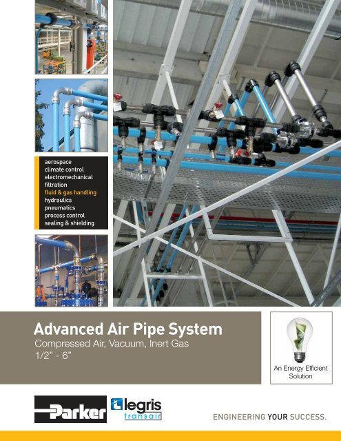
Advanced <strong>Air</strong> Pipe System<strong>Compressed</strong> <strong>Air</strong>, Vacuum, Inert Gas1/2” - 6”An Energy Effi cientSolution
TransairInnovative TechnologyTransair’s aluminum compressed air pipe system is quick to install and easy to modify. Transaircomponents are removable and interchangeable, which allows immediate and easy layout modications.Unlike the performance of steel and copper, which degrades over time due to corrosion,Transair provides clean air quality with optimum ow rate performance.Transair also offers signicant savings on installation, maintenance and operating costs comparedto traditional pipe. The quick, instant connections eliminate the need to thread or solder pipe. Laboraccounts for only 20% of the cost of installing Transair, while labor accounts for 50% to 80% of thecost of installing steel or copper systems. Transair’s aluminum pipe system signicantly reducesplant energy costs by increasing efciency, reducing pressure drops, and eliminating leaks.Available in ½” to 6” pipe sizes, the Parker Transair system features quick connect technology thatsecures connections with a simple push and provides a leak-free guarantee. The aluminum pipeeliminates corrosion, ensuring the longevity of equipment and helps to avoid frequent changes ofltration elements. Transair can also be integrated into existing copper and steel piping withoutcompromising performance, making it perfect for upgrades or expansion projects.Transair‘s additional benets include:• Energy efcient• Lower install costs• Quick connect technology • Immediate pressurization• Removable and reusable • Modular design• No corrosion• Leak-free guarantee• Full bore design• 1/2“ - 6“ pipe sizes! WARNINGFAILURE, IMPROPER SELECTION OR IMPROPER USE OF THE PRODUCTS AND/OR SYSTEMS DESCRIBED HEREIN OR RELATED ITEMS CANCAUSE DEATH, PERSONAL INJURY AND PROPERTY DAMAGE.This document and other information from Parker Hannin Corporation, its subsidiaries and authorized distributors provide product and/or system options forfurther investigation by users having technical expertise. The user, through its own analysis and testing, is solely responsible for making the nal selectionof the system and components and assuring that all performance, endurance, maintenance, safety and warning requirements of the application are met.The user must analyze all aspects of the application, follow applicable industry standards, and follow the information concerning the product in the currentproduct catalog and in any other materials provided from Parker or its subsidiaries or authorized distributors. To the extent that Parker or its subsidiaries orauthorized distributors provide component or system options based upon data or specications provided by the user, the user is responsible for determiningthat such data and specications are suitable and sufcient for all applications and reasonably foreseeable uses of the components or systems.
Contents>IntroductionTechnical specificationsSizingFlow rates and pressure dropTransair Flow CalculatorSafetyCertification and GuaranteeMaterialTransair Technology<strong>Service</strong>s020304050607080910>Products catalogRigid aluminum pipeFlexible hosePipe-to-pipe and threaded connectorsQuick assembly bracketsWall bracketsBall valves and butterfly valvesToolsFixture accessoriesHose reelsAutomatic couplers14151624272931353738>Installation guideEssential instructionsAluminum pipePipe-to-pipe connectorsQuick assembly bracketsFlexible hoseFixture accessoriesPractical informationTransair in use4244506167727683Part numbers index87Offer of Sale89
Technical specifications>Fluids• <strong>Compressed</strong> air (dry, wet, lubricated)• Vacuum• Inert gases• Other fluids: please consult us> Maximumworking pressure188 psi from -4°F to +140°F232 psi from -4°F to +115°FMaximum working pressure versus operating temperaturePressure (psi)Temperature (°F)>Vacuum level> Workingtemperature>Storagetemperature>Resistance to98.7 % (29.6’’ Hg)from -4°F to +140°Ffrom -40°F to +176°F• corrosion• aggressive environments• mechanical shocks• thermal variations• U.V.• mineral compressor oils• synthetic compressor oils• compressor oil carry over> EnvironmentMaterials used to produce the pipe and fittings are 100% recyclable.All Transair pipe, fittings and values are guaranteed silicone free.
2/3>SizingSelect the Transair diameter for your application based on required flow against pressure drop.Estimated values for: a closed loop network, a pressure of 115 psi with 5% pressure drop.LengthFlow rate164ft 328ft 492ft 984ft 1640ft 2460ft 3280ft 4265ft 5249ft 6561ftNm 3 /h Nl/min cfm 50m 100m 150m 300m 500m 750m 1000m 1300m 1600m 2000m10 167 6 16.5 16.5 16.5 16.5 16.5 16.5 16.5 25 25 2530 500 18 16.5 16.5 16.5 25 25 25 25 25 25 4050 833 29 16.5 25 25 25 25 25 40 40 40 4070 1167 41 25 25 25 25 40 40 40 40 40 40100 1667 59 25 25 25 40 40 40 40 40 40 63150 2500 88 25 40 40 40 40 40 40 63 63 63250 4167 147 40 40 40 40 63 63 63 63 63 63350 5833 206 40 40 40 63 63 63 63 63 63 76500 8333 294 40 40 63 63 63 63 63 76 76 76750 12500 441 40 63 63 63 63 76 76 76 76 1001000 16667 589 63 63 63 63 63 76 76 100 100 1001250 20833 736 63 63 63 63 63 100 100 100 100 1001500 25000 883 63 63 63 76 76 100 100 100 100 100*1750 29167 1030 63 63 76 76 76 100 100 100 100* 100*2000 33333 1177 63 76 76 76 100 100 100 100* 100* 100*2500 41667 1471 63 76 76 76 100 100* 100* 100* 100* 100*3000 50000 1766 76 76 76 100 100 100* 100* 100* 100* 100*3500 58333 2060 76 76 100 100 100* 100* 100* 100* 100* 100*4000 66667 2354 76 100 100 100 100* 100* 100* 100* 100* 100*4500 75000 2649 76 100 100 100* 100* 100* 100* 100* 100* 100*5000 83333 2943 76 100 100 100* 100* 100* 100* 100* 100* 100*5500 91667 3237 100 100 100 100* 100* 100* 100* 100* 100* 100*6000 100000 3531 100 100 100* 100* 100* 100* 100* 100* 100* 100**Pressure drop >5%Compressor(hp)2 - 1010 - 4040 - 100100 - 425> 425> Example• Main network length (ring main): 984 ft• Compressor power: 40 hp• Required flow rate: 147 cfm• Working pressure: 115 psiThe most suitable Transair diameter is: Ø 40.To size your air pipework system, you can also use the Transair Flow Calculator.For more information, refer to page 5 of this catalog.
Flow rates and pressure dropMeasurements provided by the official French testing body CETIM - Centre Technique des Industries Mecaniques.Charts are based on a 100 feet straight Transair line.Maximum flow rate with 5% pressure drop (To convert to cfm, use a coefficient of 0.588.)Flow rate (Nm3/h)Pressure (psi)Maximum flow rate with 1.45 psi pressure drop. (To convert to cfm, use a coefficient of 0.588.)Flow rate (Nm3/h)Pressure (psi)
4/5>Transair Flow CalculatorThe Transair Flow Calculator helps you to choose the most suitable diameter for your installation. Enter the flow of yourcompressor, the system pressure rating and the total equivalent length of the system. Select ring main or straight linelayout, enter your preferred unit of calculation and then click for an immediate indication of the most suitable Transairdiameter (with a pressure drop of less than 5%).> Example> Flow rate: 850 cfm at 109 psi> Ring main: 1788 feet> The recommended Transair diameter is Ø 100mm(pressure drop of 145 psi = less than 5 %)> DownloadThe new Transair Flow Calculator from our web site:www.parkertransair.com
Safety>Fire resistanceAll Transair components are non-flammable with no propagation of flame.• pipe-to-pipe and male connectors, ball valves and butterfly valves: conform to UL94HB standard• fixture clips: conform to UL94V-2 standard• flexible hoses: conform to ISO 8030 norm for compressed air applicationsand to EN 12115 norm for vacuum applications• pipe powder coat finish classified M0>ElectricalconductivityIn areas of potential risk, the earthing and electrical continuity of metallic components areobligatory. The Transair system can be used in such environments by undertaking theappropriate precautions. For more information, please consult us.>CE conformityTransair conforms to European standard 97/23 CEE - §3.3 (equipment under pressure).DECLARATION OF CE CONFORMITYSupplied in conformity with theDIRECTIVE on EQUIPMENT UNDER PRESSURE97/23/CEEWe hereby declare that all Transair connectors manufactured by Parker should be considered as pipingcomponents which designed according to sound working practice. “Piping includes in particular a pipe orsystem of pipes, tubing, fittings, expansion joints, hoses, or other pressure-bearing components as appropriate”– cf acceptance by the «pressure working group» dated 28/01/1999 and by the GTP Commissiondated 27/11/1998.Products designed according to the code of practice.Product description: Transair connectors Ø 16.5 - Ø 25 - Ø 40 - Ø 63 - Ø 76 - Ø 100Applicable approvals: AFAQ Certificate of Approval, EN ISO 9001
6/7>Certification and Guarantee>CertificationISO 9001version 2000Legris S.A. is certified ISO9001 version 2000 and operatesa Quality ManagementSystem in order to ensurethe level of quality and servicethat is expected by itscustomers.>TÜVcertificationA product certified TÜVis a pledge of safety andquality. The Group TÜVthus certifies independenttest results – in particular,the properties of the productsand the standardswhereby they were examined.>QUALICOATcertificationQUALICOAT certificationis a guarantee of the qualityof the lacquer finishapplied to Transair aluminumpipe.>ASME B31.1>ASME B31.3Transair meets the requirementof ASME B31.1 andB31.3.- which stipulates “the minimum requirementsfor the design, materials, fabrication,erection, test and inspection of power andauxiliary piping systems for industrial institutionalplants”.All Transair componentsare guaranteed for 10 years.- TRANSAIR GUARANTEE -Parker-Hannifin Corporation warrants its Transair products to be free of defects in material and workmanship for a periodof ten (10) years from the date of purchase of the products. Parker-Hannifin Corporation makes no other warranties,express or implied. This limitation explicitly excludes any implied warranty of merchantability or fitness for a particularpurpose. The sole remedy for breach of this warranty of material and workmanship or for negligence in manufacture ordesign is limited to replacement or repair, at the sole option of Parker-Hannifin Corporation, of any defective parts whichare returned to Parker-Hannifin Corporation (prepaid) within ten (10) years of original purchase. In no event shall Parker-Hannifin Corporation be liable for indirect, special, incidental or consequential damages of any kind. No allowance willbe made for repairs made by the purchaser.THIS WARRANTY IS EXPRESSLY IN LIEU OF ANY AND ALL OTHER WARRANTIES AND REPRESENTATIONS,EXPRESS OR IMPLIED, INCLUDING BUT NOT LIMITED TO, THE WARRANTY OF FITNESS FOR A PARTICULARPURPOSE AND THE WARRANTY OF MERCHANTABILITY. PARKER-HANNIFIN CORPORATIONMAKES NO WAR-RANTY THAT THE GOODS SOLD HEREUNDER ARE DELIVERED FREE OF THE RIGHTFUL CLAIM OF ANY THIRDPARTY BY WAY OF INFRINGEMENT OR OTHERWISE. THERE ARE NO WARRANTIES THAT EXTEND BEYONDTHE DESCRIPTION ON THE FACE HEREOF. THE EXCLUSIVE REMEDY FOR DEFECTIVE PRODUCTS SHALL BEONLY AS STATED HEREIN.Parker-Hannifin Corporation does not warrant the design, assembly or installation of the system, but only the Transaircomponents as stated herein. Parker-Hannifin Corporation is not responsible for improper design, assembly or installation,or for any modifications of the Transair products. The warranty herein is void upon (a) failure to follow any of theassembly or installation guidelines, (b) installation, repair or relocation of the components by a person other than a trainedand qualified installer; (c) alteration, misuse or abuse of, or damage to, any of the Transair products, (d) operationbeyond the design range, excessive pressure of stress, or mishandling in any way, (e) use other than for the intendedpurpose or in a manner other than as specified by Parker-Hannifin Corporation, or (f) improper assembly, installation,service or maintenance. This Limited Warranty, and Parker-Hannifin Corporation’s responsibility, may be further limited,but may not be expanded, by Parker-Hannifin Corporation’s terms and conditions of sale, as set forth on the reverse sidearker-Hannifin Corporation invoice.
Material1013A1016A1001E air1001E vacuumØ 16.5 - Ø 25 - Ø 40 Ø 63 Ø 76 - Ø 100powder coated aluminum powder coated aluminum TA16powder coated aluminumpowder coated aluminum powder coated aluminum TA16powder coated aluminumhose and coating: black SBRreinforcement: synthetic braidinghose and coating: black SBR / NBRreinforcement: spiral steel wirehose and coating: black SBRreinforcement: synthetic braidinghose and coating: black SBR / NBRreinforcement: spiral steel wireEW054002 polyamide with fiberglassbody: polyamide with fiberglass RP01nut: treated aluminum4088 - 4099 body: treated brassRR01nut: engineering grade plastic-FP01seal: EPDMhose and connector: black SBR/NBRreinforcement: spiral steel wirebody and pushing ring: polyamide with fiberglass- seal: NBRclamp: treated steelcartridge: polyamide with fiberglassseal: NBRAnti whip-lash strapSteel6602 - 6604 polyamide with fiberglasstreated aluminumRR616605 body: treated brassnut: polymer HR / NBRbody: treated brassnut: treated aluminum / NBRRX02stainless steel 3046606 polyamide with fiberglass treated aluminum RX12stainless steel 3046612polyamide with fiberglass treated aluminumRX04stainless steel 3046621treated aluminum -RX20stainless steel 3046625polyamide with fiberglass treated aluminumRX24stainless steel 3046651 body: treated brassnut: polyamide with fiberglass- RX64stainless steel 3046663 body: polyamide with fiberglass insert: brassbody: polyamide with fiberglassinsert: brassRX66stainless steel 3046662 polyamide with fiberglass polymère HR RX30stainless steel 3046666 body: treated aluminumnut: polyamide with fiberglasstreated aluminumVR02body: irondisc and shaft: stainless steel6676 polyamide with fiberglassbody: treated aluminumnut: polymer HRVR03nickel-plated brass6684body: treated brassnut: polyamide with fiberglassBracketzinc steel - rubber EPDM-6688EA98treated brassbody: treated ironball valve: plated brass--RA68 - RA69RA65polyamide with fiberglass -body: polyamide with fiberglassinsert: brass-Clip - Spacer polyamide with fiberglass polyamide with fiberglass0169 Adaptor brass -All Transair pipe, fittings andvalves are guaranteedsilicone free.Composite couplerHose reelBlowgunbody: polymer HR / Zamac - sleeve: polymer HR - spring and ball bearings: stainless steel - seal: nitrile - probe: treated steelmetal case - fixing: metalreinforced polyamide - treated aluminum - insert brass
8/9>Transair TechnologyThe innovative technology of Transair enables rapid and easy assembly: quick connection of components to thealuminum pipe. This technology takes into account the specific requirements of each diameter and provides theuser with an optimum safety coefficient and easy connection.> Ø 16.5 (1/2’’)> Ø 25 (7/8’’)> Ø 40 (1 1/2’’)Pipe-to-pipe and male connectorsin Ø 16.5, Ø 25 and Ø 40 can beimmediately connected to Transair pipe -simply push the pipe into the connector upto the connection mark. The gripping ringof each fitting is then automatically securedand the connection is safe.sealgripping ringtightening marksbody nut pipe> Ø 63 (2 1/2’’)Pipe-to-pipe and male connectors in Ø63 can be quickly connected to Transairaluminum pipe by means of a double clampring. This secures the connection betweenthe nut and the pipe - tightening of the nutssecures the final assembly.sealdouble clamp ringbody nut pipelugsocket head screw> Ø 76 (3’’)> Ø 100 (4’’)> Ø 168 (6’’)Pipe-to-pipe and male connectors inØ 76 and Ø 100 can be quickly connectedto Transair aluminum pipe. Position thepipes to be connected within the Transaircartridge and close/tighten the Transairclamp.sealcartridge clamp pipe
<strong>Service</strong>sA number of additional Transair services help you throughout your projects.> ProjectassistanceUnderstanding, Proximity, Responsiveness.Transair technical teams are at your disposal to study and help design your air system. Inparticular, they assist you in your project with:• Information on the Transair products and services• Guidance and training on how to assemble the system• Advice on “best practice” in order to reduce your consumption of energy• Ongoing assistance and follow-up• On-site advisory presence at construction and installation locationsOur customer service teams will coordinate a quick response to your requirements.> Customer service• Product availability• Order processing and follow-up• Delivery time-phasing and modification• Technical information> Costing service• Advice• Design softwareContact Parker Legris Transair> Wherever you are in the world, you can contact us:• by phone• by fax• by mail• by e-mail7205 E. Hampton Ave.Mesa, AZ 85209Ph. (480) 830-7764 Fax (480) 325-3571www.parkertransair.com
10/11> Transairdesign software• Installation sizing• System layout and drawing• Shopping list• Available on CD> Web site• Practical information• Downloadable literature files: catalogs,information on new products, introductoryflyers, instruction guidelines, newsletterswww.parkertransair.comZ> CAD drawingsAll Transair CAD drawings are availableonline - in DWG format.LZØGØD> SpecificationsheetsFormal technical specifications for the Transair system are available in either Word orPDF format and can be directly integrated into your own documents.
TransairSignificant Energy Savings<strong>Compressed</strong> air represents one of the largest opportunities for immediate energy savings. Plantmanagement is often surprised to hear that compressed air can represent 20-50% of a plant’s electricbill. Plant management is truly amazed when they fi nd out that using an effi cient piping systemspecifi cally designed for compressed air can reduce their energy bill by 30-60%, many times within a24-month period.For instance, a large industrial plant recently redesigned their compressed air system with Transair. Thisaccounted for 35% savings in the plant’s monthly energy bill, which paid for the system in 15 months.The plant continues to save by:• Increased air system reliability• Reduced maintenance cost andextended equipment life• Reduced system downtime, increasedproduction ratesThe results speak for themselves and show that Transair is the best performing system and the bestlong-term choice, no matter whether the project is for an extension, the modifi cation of an existing pipesystem or a new installation.ZLZØGØD
12/13> Products catalogRigid aluminum pipe14Flexible hose15Pipe-to-pipe and threaded connectors16Quick assembly brackets24Wall brackets27Ball valves and butterfly valves29Tools31Fixture accessories35Hose reels37Automatic couplers38
Rigid aluminum pipe> Clean air> Optimum flow rate performance> Lightweight> QUALICOAT certified surface finish> Two colors: blue (RAL 5012/BS1710),grey (RAL 7001) (other colors: please consult us)> Suitable fluids: compressed air, vacuum, nitrogen,argon (other fluids: please consult us)> Ø 76 and Ø 100 pipe is also available in stainlesssteel (please ask for details)> Max. working pressure:- 188 psi from -4°F to +140°F- 232 psi from -4°F to +115°F(please consult us for higher temperaturerequirements)> Vacuum: 98.7% (29.6’’ Hg)> Working temperature: -4°F to +140°F> Extruded pipe (conforms to EN 755.2,EN 755.8 and EN 573.3 standards)Ø16.52540L1LL1LBlue pipeTransair1013A17 04 00 16.5 1/2 10 9’ 9 1/4’’1004A17 04 16.5 1/2 151013A25 04 00 25 7/8 10 9’ 8 1/4’’1016A25 04 00 25 7/8 20 19’ 8 1/4’’1013A40 04 00 40 1 1/2 10 9’ 7 1/2’’1016A40 04 00 40 1 1/2 20 1 9’ 7 1/2’’Grey pipeTransairØOD (mm) ØOD (in) L1 (ft)L (ft)ØOD (mm)ØOD (in)L1 (ft)L (ft)1013A17 06 00 16.5 1/2 10 9’ 9 1/4’’1016A25 06 00 25 7/8 20 19’ 9 3/4’’1016A40 06 00 40 1 1/2 20 19’ 8 1/4’’L1LBlue pipeTransairØOD (mm)ØOD (in)L1 (ft)L (ft)1013A63 04 63 2 1/2 10 9’7 1/2’’1016A63 04 63 2 1/2 20 19’ 10’’Ø63L1LGrey pipeTransair ØOD (mm) ØOD (in) L1 (ft)L (ft)1016A63 06 63 2 1/2 20 19’ 7 1/8’’Ø76100LBlue pipeTransair ØOD (mm)ØOD (in)L (ft)TA16 L1 04 76.3 3 20TA16 L3 04 101.8 4 20Pipe sizes: 16.5 mm (1/2’’)25 mm (7/8’’)40 mm (1 1/2’’)63 mm (2 1/2’’)76.3 mm (3’’)101.8 mm (4’’ ID)
Flexible hose> Compressor outlets (absorption of vibration)> To bypass obstacles and join different levels> Expansion loops> Max. working pressure for flexible hose used forcompressed air:- 188 psi from -4°F to +140°F- 232 psi from -4°F to +115°F (please consult usfor higher temperature requirements)14/15> Max. working pressure for flexible hose usedfor vacuum: 145 psi> Vacuum: 98.7% (29.6’’ Hg)> Working temperature: -4°F to +140°F> Resistant to mineral and synthetic compressor oils> Fire resistant (conforms to ISO 8030 standard for compressedair flexible hose and to EN 12.115standard for vacuum flexible hose)Ø2540D1LD2Flexible hose for compressed air systemsFor useMin. bend with TransairTransair OD (mm) OD (in) L (ft) radius (in) pipe diameter1001E25 00 01 38 7/8 1’ 4’’ 4 251001E25 00 03 38 7/8 5’ 4 251001E25 00 04 38 7/8 6’ 7’’ 4 251001E40 00 02 54 1 1/2 3’ 3’’ 16 401001E40 00 04 54 1 1/2 6’ 7’’ 16 401001E40 00 05 54 1 1/2 9’ 10’’ 16 40Flexible hose for vacuum systemsFor useMin. bend with TransairTransair OD (mm) OD (in) L (ft) radius (in) pipe diameter1001E25V00 01 36 7/8 1’4’’ 3 251001E25V00 03 36 7/8 5’ 3 251001E25V00 04 36 7/8 6’7’’ 3 251001E40V00 07 52 1 1/2 3’3’’ 6 1/2 401001E40V00 04 52 1 1/2 6’7’’ 6 1/2 401001E40V00 05 52 1 1/2 9’10’’ 6 1/2 40Ø63D2LD1Flexible hose for compressed air systemsFor useTransair OD (mm) OD (in) L (ft)Min. bend with Transairradius (in) pipe diameter1001E63 00 08 79 2 1/2 4’7’’ 12 631001E63 00 05 79 2 1/2 9’10’’ 25 631001E63 00 06 79 2 1/2 13’1’’ 25 63Flexible hose for vacuum systemsFor useMin. bend with TransairTransair OD (mm) OD (in) L (ft) radius (in) pipe diameter1001E63V00 05 76 2 1/2 9’10’’ 10 631001E63V00 06 76 2 1/2 13’1’’ 10 63Ø76100LD1D2Flexible hose for compressed airand vacuum systemsFor useMin. bend with TransairTransair OD (mm) OD (in) L (ft) radius (in) pipe diameterFP01 L1 01 91 3 4’11’’ 14 76FP01 L1 02 91 3 6’6’’ 14 76FP01 L3 02 116 4 6’6’’ 20 101FP01 L3 03 116 4 9’10’’ 20 101Use two connectors RR01 to connect flexible hoses FP01 to Transairpipe.Anti whip-lash strapPrevents whip-lash should Transair flexible hose be disconnectedwhile under pressure. Conforms to ISO 4414 safety standard.6698 99 03
Pipe-to-pipe and threaded connectorsThe range of Transair pipe-to-pipe and stud connectors provides versatility of design and helps to overcomeconstraints often encountered with the structure of industrial buildings.> Quick connection> Full bore design*> Interchangeable and reusable> Non-flammable materials (UL94-HB standard)*Consistent inner diameter for both pipe and connectors.Ø16.52540ØGZLZØDPipe-to-pipe connectorTransairØD ØG LZ6606 17 00 16.5 34.0 120.5 33.06606 25 00 25 44.5 151.5 48.06606 40 00 40 67.0 205.0 57.0LØ63ØDZZØGTransairØD ØG LZ6606 63 00 63 91.0 171.5 25.0Pipe-to-pipe connector (clamp and cartridge)LØ DE1E1E2TransairØD L E1 E2RR01 L1 00 76 146 104 132RR01 L3 00 100 146 128 157Ø76100NCartridge (spare part)Ø DMTransair ØD M NRP00 L1 00 76 88.7 51.4RP00 L3 00 100 123 52.7
16/17> Max. working pressure:- 188 psi from -4°F to +140°F- 232 psi from -4°F to +115°F(please consult us for higher temperature requirements)> Vacuum: 98.7% (29.6’’ Hg)> Working temperature: -4°F to +140°FPipe-to-pipe connector with ventØ2540ØGZLZØDTransairØD ØG LZ6676 25 00 25 44.5 151.5 48.06676 40 00 40 67.0 205.0 57.0Ø63ØDZLZØGTransairØD ØG LZ6676 63 00 63 91.0 171.5 25.0Model supplied with 1/4” threaded fitting and Ø 8 mm push-in connection,complete with blanking plug.
Pipe-to-pipe and threaded connectorsØ16.52540LZZØGØD90° elbowTransairØD ØG LZ6602 17 00 16.5 34.0 58.0 31.06602 25 00 25 44.5 68.0 40.06602 40 00 40 67.0 107.0 62.0Ø63LZØGLZØDTransairØD ØG LZ6602 63 00 63 91.0 122.0 61.0Ø76100Ø DH90°ZZØ DHTransairØDHZRX02 L1 00 76 227 189RX02 L3 00 100 278 221Use two connectors RR01 to connect 90° elbow RX02 to Transairpipe.Male threaded 90° elbow, NPTØ16.5254063ØDØGLZ1EJ Z2HCTransairØOD(mm) C E H ØG ØJ L Z1 Z26609 17 14 16.5 1/4’’ 9.5 17 34 34 58 31 41.26609 17 22 16.5 1/2’’ 15 23 34 34 58 31 46.56609 25 22 25 1/2’’ 15 27 44.5 45.5 69.5 40.5 536609 25 28 25 3/4’’ 15 27 44.5 45.5 69.5 40.5 536609 25 35 25 1’’ 16 36 44.5 45.5 69.5 40.5 556609 40 35 40 1’’ 16 41 67 68.5 107 62 756609 40 43 40 1 1/4’’ 21.5 50 67 68.5 107 62 816609 40 50 40 1 1/2’’ 24.5 50 67 68.5 107 62 816609 40 44 40 2’’ 23 60 67 68.5 107 62 816609 63 41 63 2 1/2’’ 27 80 91 91 124 61 1066609 63 46 63 3’’ 30 95 91 91 124 61 83
18/1945° elbowØ2540ZZLØGØDTransairØD ØG LZ6612 25 00 25 44.5 57.0 29.06612 40 00 40 67.0 90.0 45.0LØ63ZØGØDTransairØD ØG LZ6612 63 00 63 91.0 100.0 61.0Ø76100135°L2ØDTransairØD L1 L2RX12 L1 00 76 235.5 151.4RX12 L3 00 100 271.4 184.3Use two connectors RR01 to connect 45° elbow RX12 to Transairpipe.Ø63Male threaded 45° elbow, NPTTransairØOD(mm) C E H ØG ØJ L Z1 Z2Ø2540ØDØGEJZ2HC6619 25 22 25 1/2’’ 15 27 44.5 45.5 61.5 32.5 426619 25 28 25 3/4’’ 15 27 44.5 45.5 61.5 32.5 426619 25 35 25 1’’ 16 36 44.5 45.5 61.5 32.5 446619 40 35 40 1’’ 16 41 67 68.5 94 45 58.56619 40 43 40 1 1/4’’ 21.5 50 67 68.5 94 45 646619 40 50 40 1 1/2’’ 24.5 50 67 68.5 94 45 646619 40 44 40 2’’ 23 60 67 68.5 94 45 61
Pipe-to-pipe and threaded connectorsØ16.52540HØDØGZ1LZ1Z2Equal teeTransair ØD G H L Z1 Z26604 17 00 16.5 34.0 58.0 120.5 34.0 31.06604 25 00 25 44.5 67.5 151.5 48.0 40.06604 40 00 40 67.0 102.5 205.0 57.0 57.0Ø63ØDHZ1LZ1ØGZ2TransairØD G H L Z1 Z26604 63 00 63 91.0 122.0 245.0 61.0 61.0Ø76100Z2LZ1Ø DTransair ØD L Z1 Z2RX04 L1 00 76 290 145 145RX04 L3 00 100 310 155 135Use three connectors RR01 to connect equal tee RX04 to Transair pipe.Ø16 Ø25 6340Z2LZ1ØGØD2ØD1Reducing teeTransair ØD1 ØD2 ØG H L Z1 Z2H 6604 63 40 63 40 91.0 161.0 245.0 61.0 116.0Ø63Ø76 Ø100 76100Z2LØ D2Z1Ø D1Transair ØD1 ØD2 LZ1 Z2RX24 L1 40 76 40 290 145 104RX24 L1 63 76 63 290 145 163RX24 L3 40 100 40 310 155 116.5RX24 L3 63 100 63 310 155 175.8RX04 L3 L1 100 76 310 155 135Use two connectors RR01 to connect a reducing tee to Transair pipes Ø 76and Ø 100 and to connect pipe-to-pipe connector 6606 to Transair pipesØ 40 and Ø 63.Reducing TeeRX24 L1 40RX24 L3 406625 40 00
20/21Ø76100Z2LZ1Ø DThreaded teeTransair ØD C (in) LZ1 Z2RX20 L1N04 76 1/2 290 145 63RX20 L3N04 100 1/2 310 155 75.8CUse two connectors RR01 to connect threaded tee RX20 to Transair pipe.Plug-in reducerØ16.52540ØD1ZLØG ØD2Transair ØD1 ØD2 ØGZ6666 17 25 25 16.5 34.0 50.0 77.06666 25 40 40 25 44.5 71.0 99.0LTransair ØD1 ØD2 ØG L6666 40 63 63 40 67.0 112.5Ø63LØGØD22580Ø 63Ø 6361116Ø 40Ø 40Ø76100ØD1LØD2Transair ØD1 ØD2 LRX64 L1 63 76 63 230RX64 L3 63 100 63 250RX66 L3 L1 100 76 192.5Use one connector RR01 to a connect plug-in reducer to Transair pipesØ 76 or Ø 100 and one pipe-to-pipe connector 6606 to connect toTransair pipe Ø 63.
Pipe-to-pipe and threaded connectorsØ16.516.525254040HELØGØDVented end capTransair ØD E ØGH L6625 17 00 16.5 25.5 34.0 45.5 62.56625 25 00 25 33.0 44.5 47.0 75.06625 40 00 40 34.5 67.0 55.0 98.516.5mm: supplied with LF3000 6mm plus. Model Ø 25, Ø 40 and Ø 63:supplied with LF3000 5/16’’ (8mm) plug.LØ63HØGTransair ØD E ØG H L6625 63 00 63 31.0 91.0 74.0 11116.5mm: supplied with LF3000 6mm plug. Model Ø 25, Ø 40 and Ø 63:supplied with LF3000 5/16’’ (8mm) plug.LEnd capØ76100Ø DTransair ØD LRX25 L1 00 76 99.6RX25 L3 00 100 107.4Use one connector RR01 to connect end-cap RX25 to Transair pipe.Male threaded connector, NPT threadØ16.52540HEØDØGCTransair ØD EC ØG H6605 17 14 16.5 1/4’’ 9.5 34.0 62.56605 17 22 16.5 1/2’’ 15.0 34.0 68.06605 25 22 25 1/2’’ 15.0 44.5 70,56605 25 28 25 3/4’’ 15.0 44.5 71.56605 25 35 25 1” 16.0 44.5 71.56605 40 35 40 1” 16.0 67.0 111.56605 40 43 40 1 1/4’’ 21.5 67.0 111.56605 40 44 40 2’’ 23 67.0 111.56605 40 50 40 1 1/2’’ 24.5 67.0 114.5Ø63HEØ DØ GCTransair ØD C E6605 63 44 63 2” 20.0 91.0 118.56605 63 41 63 2 1/2” 25.0 91.0 130.56605 63 46 63 3” 27 91.0 140.0ØGH
22/23Ø16.52540LHØDCMale adaptor, NPT threadTransair ØD (mm) C (in)LH6621 17 22 16.5 1/2’’ 42.2 5.06621 25 22 25 1/2’’ 49.0 7.06621 25 28 25 3/4’’ 49.0 7.06621 25 35 25 1” 49.0 7.06621 40 43 40 1 1/4’’ 73.7 8.06621 40 50 40 1 1/2’’ 75.7 10.0Ø76LHØDTransair ØD (mm) C (in) LHRR21 L1N20 76 2 1/2’’ 125 20RR21 L1N24 76 3’’ 125 20Use one connector RR01 to connect male adaptor RR21 to Transair pipe.CØ2540ØGØDØD46L2 NCZLL1L2 N N NZL1N N N NLKZZØ12HM N19,54 port manifoldTransair ØD G L L1 L2 N Z6651 25 12 04 25 44.5 271.0 151.0 23.0 35.0 107.06651 40 12 04 40 67.0 400.0 204.0 27.0 50.0 150.0Supplied with four Ø12 mm plugs.6 port manifoldTransair ØD C L L1 L2 K N Z H M6653 25 22 06 25 1/2’’ 463 300 25 448 50 204 74 86.56653 40 22 06 40 1/2 ‘‘ 526 310 25 469 50 217 83 104.5Supplied with 1/2’’ NPT ports.Ø76100D3D2D1ELØ DFlangeTransair ØD DN D1 D2 D3 E LRX30 L1 00 76 65 185 145 18 10 75RX31 L1 00* 76 80 200 160 18 10 75RX30 L3 00 100 100 220 180 18 10 75RX31 L3 00* 100 100 220 180 18 10 75* RX31 dimensions conform to ANSI standards.Flange gasketTransairFor use with flangeØDreferenceEW05 L1 00 76 RX30/RX31 L1 00EW05 L3 00 100 RX30/RX31 L3 00Flange bolt kitTransair C LEW06 00 01 5/8’’ 60Contains eight bolts and eight nuts.
Quick assembly direct feed bracketsFor rigid drops with horizontal takeoff or for all types of air supply withrigid pipe or flexible hose on aninstallation which incorporates anefficient air dryer.> Optimum flow> Compact> Well adapted for most originalequipment manufacturer (OEM)applications and for use withneutral gases> Quick installation without anycutting of pipeSimple reducing bracketØ2540LØD1ØGNZMTransair ØD1 ØD2 M G L N ZRA69 25 17 25 16.5 92 34 37 52 47.5RA69 40 25 40 25 117 44.5 37 74 61To drill Transair pipe, use drilling tools 6698 02 01 and 6698 02 02.ØD2ØD2Ø76100C1LC2ETransair ØD C1 C2ELRR63 L1N08 76 1” M12 50 137RR63 L3N08 100 1” M12 80 137Nitrile Seals. Supplied with Ø 25 - 1” adaptor (6621 25 35). To drill Transairpipe, use drilling tool EW09.Transair ØD C1 C2ELRR89 L1N08 01 76 1” M12 50 137RR89 L3N08 01 100 1” M12 80 137EPDM Seals. Supplied with Ø 25 - 1” adaptor (6621 25 35). To drill Transairpipe, use drilling tool EW09.Simple bracket with thread (NPT)Ø2540LØDNMTransair ØD C L N MRA68 25N04 25 1/2’’ 37 52 86RA68 40N04 40 1/2’’ 37 74 100Supplied with brass plug. To drill Transair pipe, use drilling tools 6698 02 01and 6698 02 02.C
24/25Quick assembly bracketsNew generation quick assemblybrackets are recommended forvertical or horizontal take-offs,using either rigid pipe or flexiblehose.> Integral water retention device> Very high flow> Quick installation without anycutting of pipeQuick assembly bracketØ2540Transair ØD1 ØD2 M ØG L N Z6662 25 17 25 16.5 139.5 34 36 63.5 826662 25 00 25 25 134 44.5 36 63.5 746662 40 17 40 16.5 154 34 37.5 76.5 896662 40 25 40 25 149.5 44.5 37.5 76.5 82To drill Transair pipe, use drilling tools 6698 02 01 and 6698 02 02.LNØ63MØD1ZTransair ØD1 ØD2 M G L N Z6662 63 25 63 25 166.5 44.5 50 108.5 75To drill Transair pipe, use drilling tool 6698 02 02.ØGD2Ø2540Quick assembly mini-bracket with female thread(NPT)Transair ØD1 C M L N6663 25 22 25 1/2’’ 117.5 36 63.56663 40 22 40 1/2’’ 132 37.5 76.5Supplied with brass plug. To drill Transair pipe, use drilling tools 6698 0201 and 6698 02 02.Ø63Transair ØD1 C M L N6663 63 22 63 1/2’’ 138.9 50 98.56663 63 28 63 3/4’’ 138.9 50 98.5Supplied with brass plug. To drill Transair pipe, use drilling tool 6698 02 01.Ø254063LØD1MCNL1L2Quick assembly bracket with pre-assembled ballvalve, NPTTransair ØD1 C L L1 L2 M N6668 25 22 25 1/2’’ 256 32 155 40 236668 40 22 40 1/2’’ 270 39 162 45 316668 63 22 63 1/2’’ 275 63 142 60 486668 63 28 63 3/4’’ 297 63 146 60 48
Pressurized system outlets> Ideal for fast assembly of new pressurised outlets,without venting the compressed air system.> The drilling tool can be used with moststandard drills.We recommend, however, that the pipe system is vented prior to the addition of an outlet. Thanksto the lateral dismantling capability of Transair pipe and the use of quick assembly brackets, thisoperation can be completed very quickly (less than seven min. for a new outlet) and guarantees theinterior cleanliness of the system.Pressurized system bracketØ2540TransairØDEA98 06 01 25EA98 06 02 40Bracket with ball valve (1/2” NPT thread)Ø63TransairØDEA98 06 03 63Bracket with ball valve (1/2” NPT thread)Pressurized system drilling toolTransair C ØD L E NEA98 06 00 1/2’’ 13 330.0 154.0 30.5
26/27Wall brackets> 1, 2 or 3 ports> For wall or machine mounting> Supplied with brass plug> Drain outlet 1/4’’> Working pressure:- 188 psi from -4°F to +140°F- 232 psi from -4°F to +115°F (please consult us forhigher temperature requirements)> Non-flammable (conforms to UL94-HB standard)> Vacuum: 98.7% (29.6’’ Hg)> Working temperature: -4°F to +140°F66,5ØD1 port 45° wall bracket, NPTZ19,5N46 C2 C1 HKTransair ØD C1 C2H Z K N6640 17 22 16.5 1/2’’ 1/4’’ 89.5 63.5 84.5 826640 25 22 25 1/2’’ 1/4’’ 92.5 63.5 84.5 82MC11 port 45° threaded wall bracket, NPT19,5N46C3KHC2Transair C1 C2 C3 H K M N6642 22 22 1/2’’ 1/2’’ 1/4’’ 64 84.5 66.5 82ØD66.52 port wall bracketØ16.525HC1ØGK66,5ØDN19,5C2Transair ØD C1 G H K NC26684 17 22 16.5 1/2’’ 1/4’’ 34 65 74.5 826684 25 22 25 1/2’’ 1/4’’ 44.5 81 74.5 822 port 45° wall bracket, NPTZ19,5N46 C2KHC1Transair ØD C1 C2 H Z K N6689 17 22 16.5 1/2’’ 1/4’’ 89.5 63.5 84.5 826689 25 22 25 1/2’’ 1/4’’ 92.5 63.5 84.5 82NC12 port threaded wall bracket19,5HC2TransairC1C2C3HKMNMKC36688 22 22 1/2’’ 1/2’’ 1/4’’ 48 72.5 66.5 82MC12 port 45° threaded wall bracket, NPT19,5N46 C3KHC2Transair C1 C2 C3 H K M N6691 22 22 1/2’’ 1/2’’ 1/4’’ 64 84.5 66.5 82
Wall brackets66,53 port wall bracket, NPTØD19,5ZHTransair ØD C1 C2H Z K NØN46C2KC16696 25 22 25 1/2’’ 1/4’’ 92.5 63.5 84.5 8225LC13 port threaded wall bracket, NPT19,5HTransair C1 C2 C3 H K M NN46C3C26636 28 22 3/4’’ 1/2’’ 1/4’’ 64 84.5 66.5 82KØD1 port 45° wall bracket with ball valve, NPTNZHTransair ØD C1 C2 H Z K N6679 17 22 16.5 1/2’’ 1/4’’ 148.5 123 84.5 69.56679 25 22 25 1/2’’ 1/4’’ 173 142 84.5 108.5C146KC2ØD2 port 90° wall bracket with ball valve, NPTNØ16.5C146KZHC2Transair ØD C1 C2 H Z K N6675 17 22 16.5 1/2’’ 1/4’’ 137 111.5 74.5 69.56675 25 22 25 1/2’’ 1/4’’ 163 132 74.5 108.525ØD2 port 45° wall bracket with ball valve, NPTNTransairØDC1C2HZKNZH6694 17 22 16.5 1/2’’ 1/4’’ 148.5 123 84.5 69.56694 25 22 25 1/2’’ 1/4’’ 173 142 84.5 108.5C146C2KØD3 port wall bracket with ball valve, NPTNHZTransair ØD C1 C2 H Z K N6638 25 22 25 1/2’’ 1/4’’ 173 142 84.5 108.5C146 C2K
Ball valves28/29Transair ball valves and butterfly valves placed regularly throughout the system at key locations,such as compressor outlets and upstream of pneumatic tools, allow ease of system isolation and pipereconfiguration / maintenance.> Quick connection> Available in lockable version (only in 16.5mm and 25mm)> Manual or piloted operation (only in 25mm and 40mm)Double female, ventedØD ØGNTransair ØD G L N Z1 Z24089 17 00 16.5 34.0 120.0 69.5 29.0 42.04088 25 14 25 44.5 152.0 108.5 40.0 55.0Ø16.525Z1LZ2Model 4089 17 00: supplied with Ø6 mm plug.Model 4088 25 14: supplied with Ø8 mm plug.Lockable valve, ventedTransair ØD G L N Z1 Z24099 17 00 16.5 34.0 121.0 69.0 29.0 42.04099 25 00 25 44.5 151.7 108.3 40.0 55.0Model 4099 17 00: supplied with Ø 6 mm plug.Model 4099 25 00: supplied with Ø 8 mm plug.Double female valveNØ40ØGLØDTransair ØD G L N Z4002 40 00 40 67.0 205.0 122.0 57.0ZZØ63ØDØGLZ1Z2NTransair ØD G L N Z1 Z24002 63 00 63 91.0 278.0 185.0 84.0 98.04012 63 00* 63 91.0 278.0 185.0 84.0 98.0*lockableBall ValveØ76100Transair ØD A B D L K RVR01 L1 00 76 102 75 185 170 145 320VR01 L3 00 100 136 104 220 190 180 380Nitrile seal. Supplied with fixing bolts.
Valves> Max. working pressure:- 188 psi from -4°F to +140°F- 232 psi bar from -4°F to +115°F(please consult us for higher temperaturerequirements)> Vacuum: 98.7%(29.6’’ Hg)> Working temperature: -4°F to +140°FButterfly valveØ76100Transair ØD (in) DN G M N EVR02 L1 01 3 80 145 300 250 50VR02 L3 01 4 100 180 270 210 56Seal cast in one piece (do not use any flange gasket for mounting with aflange). Model with CE marking. Supplied with fixing bolts. Lockable version.EPDM Seal.Remote control shut-off valveLTransairØD G L Z4230 00 40 40 67 261 85.0ØDZØ4ZØ4ØGMin. working pressure: 58 psi • Max. working pressure: 235 psiThe Transair remote control shut-off valve is supplied with a pluggedvent hole. This allows venting of the downstream network, after closingthe valve.Ø40Pilot kitLTransair H K K1 L4299 03 01 145 106 70 82HKThis pilot kit comprises: pneumatic ON/OFF switch (maximum 235 psioperating pressure), twin 4 mm OD polyurethane tube (length 10 m) andplastic box.K1
Tools30/31> Practical tools for the installation and extension of Transair air pipe systems.> Presented in a carrying case or available as separate parts.Tool caseØ16.5to63Transair H L I6698 00 03 315 290 105This tool case simplifies the use and transportation of tools. It containsall the tools necessary for completing an installation:- Drilling jigs 6698 01 01 and 6698 01 02- Drilling tools 6698 02 01 and 6698 02 02- Cutter for rigid pipe 6698 03 01- Chamfer tool 6698 04 01- Deburring tool 6698 04 02- Set of tightening spanners 6698 05 03- Marking tool 6698 04 03ØØ7616.5100to100Ø162540 Ø16.5toØ 4063Pipe cutterTransairUsed forLHTransair pipe6698 03 01 230 98 Ø 16.5 - 25 - 40 - 63EW08 00 01 360 155 Ø 63 - 76 - 100Drilling jig for rigid aluminum pipeTransair H L6698 01 01 120 80After drilling, de-burr and clean the pipe.Drilling jig for rigid aluminum pipeØ63HTransair H L6698 01 02 134 155After drilling, de-burr and clean the pipe.L
ToolsDrilling tool for aluminum pipeØ25Transair ØD1 ØD2 HForTransair pipe6698 02 02 16 12 71 Ø 25mmDrilling tool 6698 02 02 allows the installation of Ø 25 Transair brackets.Can be used with all types of drill.Ø4063Transair ØD1 ØD2 HForTransair pipe6698 02 01 22 12 71 Ø 40 - 63mmDrilling tool 6698 02 01 allows the installation of Ø 40 and Ø 63 Transairbrackets. It is also used to create the two holes needed for doubleclampring connectors when cutting to length Ø 63 Transair pipe.Ø406376100Transair ØD1 ØD2 HForTransair pipeEW09 00 22 22 12 71 Ø 40 - 63mmEW09 00 30 30 12 71 Ø 76 - 100mmDrilling tool EW09 00 03 allows the installation of Transair direct feedbrackets. After drilling, it is important to de-burr and clean the pipe.Ø16.5to100Deburring tool for aluminum pipeTransairL6698 04 02 140Ø16.52540Chamfer tool for aluminum pipeTransairH6698 04 01 64For 16.5, 25 and 40mm.
32/33Marking tool for aluminum pipeØ16.52540HL1L2TransairHL1L26698 04 03 88 73 33The marking tool enables connectionguidelines to be marked on cutlengths of Transair pipe. Thesemarks indicate the insertion limitsof the pipe into each fitting in orderto ensure good airtight connectionand security of grip.Spanner wrenches for Ø 63mm fittingsØ63Transair6698 05 03This set includes two tightening spanners.Pressurised system drilling toolTransair C ØD L E NEA98 06 00 1/2’’ 13 330.0 154.0 30.5
ToolsØ16.52540Portable tool kitTransairVEW01 00 02 14This case contains: one portable tool, one 14V battery and batterycharger.Ø63Jaws for portable toolØ76100Ø76100E1E2L1L2Transair ØD E1 E2 L1 L2EW02 L1 00 76 103 52 154 46EW02 L3 00 100 103 71 154 4614V battery for portable toolTransairVEW03 00 01 14
Fixture accessories34/35> Easy adaptation for all pipework configurations> For suspension of pipes, from walls, partitions, beams, cable trays, Canalis electrical installations, etc,vertically or horizontally> Perfectly suited for use with Transair systems> Non-flammable (conforms to UL94V-2 standard)Fixing clip for rigid pipeØ16.52540CØDLKHH1Transair ØD C H1 H K L6697 17 01 16.5 1/4’’ 46 61 30 32.56697 25 01 25 1/4’’ 46 65.5 30 38.56697 40 01 40 1/4’’ 46 74.5 30 50Transair fixing clips are designed to bear a maximum weight of 44lbs.However, to ensure good stability for the system, we recommend the use ofat least two clips per pipe i.e.:- maximum 5 ft space between clips for 10 ft lenghts of pipe- maximum 10 ft space between clips for 20 ft lenghts of pipeUse only this clip for fixing Transair rigid pipe, all other type of pipe clips areto be avoided. Fix the clip to a rigid support (U-channel, cable tray) to allowfor expansion while retaining the pipe.CKTransair ØD C H1 H K L6697 63 01 63 3/8’’ 90 127.5 30 73.5Ø63ØDLHH1Transair fixing clips are designed to bear a maximum weight of 44lbs.However, to ensure good stability for the system, we recommend the use ofat least two clips per pipe i.e.:- maximum 5 ft space between clips for 10 ft lenghts of pipe- maximum 10 ft space between clips for 20 ft lenghts of pipeUse only this clip for fixing Transair rigid pipe, all other type of pipe clips areto be avoided. Fix the clip to a rigid support (U-channel, cable tray) to allowfor expansion while retaining the pipe.Ø76100CØ DTransair ØD CER01 L1 00 76 3/8’’ER01 L3 00 100 3/8’’Transair fixing clips are designed to bear a maximum weight of 44lbs.However, to ensure good stability for the system, we recommend the use ofat least two clips per pipe i.e.:- maximum 5 ft space between clips for 10 ft lenghts of pipe- maximum 10 ft space between clips for 20 ft lenghts of pipeUse only this clip for fixing Transair rigid pipe, all other type of pipe clips areto be avoided. Fix the clip to a rigid support (U-channel, cable tray) to allowfor expansion while retaining the pipe.Ø76100Transair ØD CEX01 L1 00 76 3/8’’EX01 L3 00 100 3/8’’Transair fixing clips are designed to bear a maximum weight of 44lbs.However, to ensure good stability for the system, we recommend the use ofat least two clips per pipe i.e.:- maximum 5 ft space between clips for 10 ft lenghts of pipe- maximum 10 ft space between clips for 20 ft lenghts of pipeUse only this clip for fixing Transair rigid pipe, all other type of pipe clips areto be avoided. Fix the clip to a rigid support (U-channel, cable tray) to allowfor expansion while retaining the pipe.
Fixture accessoriesSpacerØ16.5to63HTransair ØD H H1 K LL K 6697 00 03 11 49.5 44 34 33ØDThis spacer, in association with a Transair pipe clip, allows consistentH1alignment of pipes when different diameters of pipe are run concurrentlyin the same line.Ø63Ø4046mm90mm44mmThreaded rod adaptorC1HETransair C1EH0169 00 05 00 1/4’’ 16 30The use of this adaptor facilitates the suspension of Transair 16.5, 25 or40mm with 3/8’’ threaded rod.U-channelLTransairHL(ft)L16699 01 01 25 6’6’’ 25HL1U-channel fixing bracketLHTransairH6699 01 02 106 40This set comprises:• 1 bracket• 1 fixing bolt & nut• 1 nut• 1 rail profile end capL
Hose reels36/37Hose reels> Optimize productivity and the safety of yourwork area> Prevent hose damage occurring on theworkshop floor> Maximum working pressure, dependant on themodel:- 6698 11 11: 250 psi- 6698 10 02: 250 psi> Working temperature: -4°F to +14°FLight series hose reel25 ftLØDHMax. PressureTransair Hose i.d. (in) (psi) H L6698 11 11 3/8 250 251 300Hose clutch with free returnOutlet connection 1/4 male - 3/8’’ inletLight series hose reel50 ftLHMax. PressureTransair Hose i.d. (in) (psi) H L6698 11 12 3/8 250 251 390Hose clutch with free returnOutlet connection 1/4 male - 3/8’’ inletØD
Composite automatic safety couplers> For quick and repetitive connection and disconnection> 100% safety – ISO 4414 and European EN 983compliant> Very high flow, extremely low pressure loss> Lightweight and robust> Improved hand grip> Fast vent time> Male thread with integral seal> Suitable fluids: compressed air, argon, nitrogen(please consult us for other fluids)> Max. working temperature: 232 psi> Working temperature: from -4°F to +140°FMale NPTFemale NPTCouplerwith hosetailISO B1/4’’SafetyTransair CCP05 U1N02 1/4’’CP05 U1N03 3/8’’CP05 U1N04 1/2’’Transair CCP15 U1N02 1/4’’CP15 U1N03 3/8’’CP15 U1N04 1/2’’TransairØD(mm)CP21 U1 06 6CP21 U1 08 8CP21 U1 10 10Male NPTFemale NPTCouplerwith hosetailISO B3/8’’SafetyTransair CCP05 U2N02 1/4’’CP05 U2N03 3/8’’CP05 U2N04 1/2’’Transair CCP15 U2N02 1/4’’CP15 U2N03 3/8’’CP15 U2N04 1/2’’TransairØD(mm)CP21 U2 08 8CP21 U2 10 10CP21 U2 13 13Male NPTFemale NPTCouplerwith hosetailARO1/4’’SafetyTransair CCP05 A1N02 1/4’’CP05 A1N03 3/8’’CP05 A1N04 1/2’’Transair CCP15 A1N02 1/4’’CP15 A1N03 3/8’’CP15 A1N04 1/2’’TransairØD(mm)CP21 A1 06 6CP21 A1 08 8CP21 A1 10 10SafetyISO B 1/4’’ISO 6150 BAFNOR NF 49-053US.MIL.C4109CEJN 310RECTUS 23-24ISO B 3/8’’ISO 6150 BAFNOR NF 49-053US.MIL.C4109CEJN 430RECTUS 30ARO 1/4’’ARO 210CEJN 300ORION 44510PARKER 50RECTUS 14-22Flow curve –pressure losslosspressurein psi12108• • •6•4•2• Cv=1.24•0 •0 10 20 30 40 50flow (SCFM)
100/101 38/39Transair composite automatic couplers comply with worldwide ISO 4414 and European EN 983safety standards. Disconnection is by a double twist of the sleeve.1st rotation in directionof the arrow:pressure rapidly vented out,plug side.2nd rotation in directionof the arrow:safe disconnection of bodyand plug.ISO B1/4’’ISO B1/4’’ISOISOB3/8’’3/8’’Male plugNPTTransair9084 23 14 1/4’’9084 23 18 3/8’’Male plugNPTTransairCC9084 30 14 1/4’’9084 30 18 3/8’’Female plugNPTTransairC9083 23 14 1/4’’9083 23 18 3/8’’Female plugNPTTransairC9083 30 14 1/4’’9083 30 18 3/8’’PlugwithhosetailTransairPlugwithhosetailØD(mm)9085 23 56 69085 23 08 89085 23 60 10TransairØD(mm)9085 30 08 89085 30 60 109085 30 62 13Male plug NPTFemale plugNPTARO1/4’’TransairC9084 22 14 1/4’’9084 22 18 3/8’’TransairC9083 22 14 1/4’’9083 22 18 3/8’’losspressurein psi12108• • •6•4•2• Cv=2.4900 • •20 40 60 80 100flow (SCFM)
TransairOptimal Machine and Tool EfficiencyThe clean air quality and “full bore” design of Transair provides optimal machine and tool effi ciency. Transair’saluminum pipe ensures a total absence of corrosion. The inner pipe surface consistently delivers clean compressedair. Transair prevents the problems caused by rust, which affects galvanized steel systems. Due toconsistent clean quality air, from compressor outlets to machines, Transair aluminum pipe ensures higherlongevity of equipment and avoids frequent changes of fi ltration elements.The “full bore” design of Transair’s components, the low friction coeffi cient of aluminum pipe, and the sealingcharacteristics of the system ensure optimal and constant fl ow throughout. Due to its innovative technology,Transair gives better performance in terms of improved fl ow and reduced pressure drop.Example:• A 63mm Transair system gives a fl ow performance better than that of a nominal (2 1/2”) galvanizedsteel system.Example:• S teel pipe can erode by a 40% factor over its lifetime. Transair maintains its smooth bore through outits lifetime.ZLZØGØD
40/41> Installation guideEssential instructionsInstallation instructionsSound engineering practice for the optimization of an air pipe systemAluminum pipeGeneralAluminum pipe sectionPipe-to-pipe connectorsGeneralConnection / DisconnectionPractical examplesDo’s / Don’tsQuick assembly bracketsGeneralInstalling a quick assembly bracketPractical examplesFlexible hoseGeneralSystem connectionDo’s / Don’tsFixture accessoriesAttachmentsSupporting a Transair system42434446505255596162656768717274Practical informationZ dimensionsExpansion / ContractionConversion chartsTransair in use76778183
Installation> Installation instructions> GeneralPrior to the installation of a Transair compressed air distribution system, the installer should ensure that the installation areacomplies with any regulations applicable to areas exposed to explosive hazards (in particular the effect of static electricityin a silo area). Transair should be installed downstream of the compressed air receiver, or after the dryer. Flexible Transairhose can be installed at the start of the system in order to eliminate any sources of vibration and to facilitate maintenanceoperations. When maintaining or modifying a Transair system, the relevant section should be vented prior to the commencement ofany work. Installers should use only Transair components and accessories, in particular Transair pipe clips and fixture clamps.The technical properties of the Transair components, as described in the Transair catalog, must be respected.> Pressurizing the systemOnce the Transair installation has been installed and prior to pressurizing, the installer should complete all tests,inspections and compliance checks as stated in any contract and according to sound engineering practice and current localregulations.> Transair pipe and hosesTransair pipe should be protected from mechanical impact, particularly if exposed to collision with fork-lift trucks or whensited in an environment with moving overhead loads. Similarly, rotation of the pipe and pipe supports should be avoided.Transair pipe must not be welded. Flexible Transair hoses should be used in accordance with the recommendations of theinstallation guidelines.Note: In certain situations, Transair aluminum pipe may be formed with a bend - please contact us for further information.> Expansion / contractionExpansion and contraction of the system should be calculated prior to installation. The system designer and installer shouldcalculate the elongation or retraction of each Transair line according to the recommendations in this installation guide.> Component assemblyTransair components are provided with assembly instructions for their correct use - simply follow the methods andrecommendations stated in this document.> Transair installations - situations to avoid> installation within a solid mass (concrete, foam, etc.)> the hanging of any external equipment to Transair pipe> the use of Transair for earthing, or as a support forelectrical equipment> exposure to chemicals that are incompatible with Transaircomponents (please contact us for further details)
42/43> Sound engineering practice for the optimization of an air pipesystem> When installing a Transair system, the work should be performed in accordance with good engineeringpractice.> Bends and bypasses represent sources of pressure drop. To avoid excessive pressure loss, usemodular consoles to offset the network and to bypass obstacles. Keep in-line pipe diameter reductionsto a minimum.> Maintain a consistent level of good quality air by use of adequate filtration at the compressor outlet.> The diameter of the pipe will influence pressure drop and the operation of point-of-use equipment.Select the diameter according to the required flow rate and acceptable pressure drop at the point ofuse.> Position drops should be as close as possible to the point of use.
Transair aluminum pipe> GeneralØ 16.5 Ø 25 Ø 40Deburred and chamfered pipeDeburred and chamfered pipeDeburred and chamfered pipeØ 63 Ø 76 Ø 100 – Ø 168> PresentationPipe pre-drilled at each end withtwo 22 mm diameter holes,deburred and chamferedPipe lugged at each end,deburred and chamferedPipe lugged at each end,deburred and chamferedTransair aluminum pipe is supplied ready for use.No particular preparation (cutting, deburring,chamfering, etc.) is required.Thanks to the rigidity of Transair aluminumpipe, temperature-related expansion/contractionis reduced to a minimum. The Transair systemretains its straightness, and hence its performance,over time (reduction of pressure dropcaused by surface friction).Transair aluminum pipe is calibrated andfits perfectly with all Transair components.Each connection is automatically secured andthe seal is optimized, which minimizes corrosionto the internal surface.Transair aluminum pipe has a protectivepowder coating (QUALICOAT certified)and is thus protected from external corrosion.Its color allows the system to beimmediately identified and gives a clean andaesthetic overall appearance.Standard colors available:• blue (RAL 5012/BS1710)• grey (RAL 7001)(please contact us for other colors)Transair aluminum pipe is available in sevendiameters in 1/2’’ thru 6’’.> ApplicationsTransair Ø 16.5 - Ø 25 - Ø 40 - Ø 63 - Ø 76 - Ø 100 - Ø 168 aluminum pipe has beenspecially designed for compressed air, vacuum and inert gases (argon, nitrogen) - pleasecontact us for other fluids.
44/45Pipe calibration is a guaranteeof secure connection and sealingType of pipe> MarkingTransair 37x40 calibrated aluminum pipe, Pmax 188 psi SH 117836/002inside Ø x outside Ø (mm)Maximum operatingpressure from -4°F to +140°FManufacturing batchThe transported fluid can be instantly identified by the color of the pipeex: Blue pipe compressed air networkex: Grey pipe vacuum networkOnly on Ø 16.5 - Ø 25 - Ø 40 aluminum pipe> ConnectionindicatorTransair 37x40 calibrated aluminum pipe, 188 psi SH 117836/002Connection indicatorOnly on Ø 16.5 - Ø 25 - Ø 40 - Ø 63 aluminum pipe> Drilling locator:mark lines forcorrect drillingLocatorDrilling locators are used to correctly position Transair brackets onto the pipe.There are two locators on each pipe. The second locator is used to position asecond bracket perpendicular to a first bracket.
Transair aluminum pipe> Aluminum pipe section> Ø 16.5Ø 25 - Ø 40> ToolsPipe cutter foraluminum piperef. 6698 03 01Chamfer tool foraluminum piperef. 6698 04 01Deburring tool foraluminum piperef. 6698 04 02Marking tool foraluminum piperef. 6698 04 032134> Procedure1 - Cutting the pipe:- place the pipe in the pipe cutter- position the blade onto the pipe- rotate the pipe cutter around the pipewhile gently tightening the wheel2 - Carefully chamfer the outer edges3 - Also deburr the inner end of the pipe4 - Trace the connection indicator using themarking toolThe insertion lengths for Ø 16.5 - Ø 25 - Ø 40 connectors are 25 mm, 27 mm and 45 mm respectively,with the exception of the end cap, ref. 6625, for which the insertion lengths are of 39 mm, 42 mm and 64 mmrespectively.
46/47> Ø 63> ToolsPipe cutter foraluminum piperef. 6698 03 01FileDeburring tool foraluminum piperef. 6698 04 02Drilling tool foraluminum piperef. 6698 02 01Drilling jig foraluminum piperef. 6698 01 02Drill123> Procedure41 - Cutting the pipe:- place the pipe in the pipe cutter- position the blade on the pipe- rotate the pipe cutter around the pipewhile gently tightening the wheel2 - Carefully chamfer the outer edges3 - Also deburr the inner end of the pipe4 - Drill the two clamp holes using the drilling jig(6698 01 02) and the Ø 22 mm drilling tool(6698 02 01). Loosen the jig, release thepipe, then deburr both holes. Ensure thatall outer and inner surfaces are smooth andclear of burrs and potential sharp edges.
Transair aluminum pipe> Aluminum pipe section> Ø 76 - Ø 100> ToolsPipe cutter foraluminum piperef. EW08 00 01FilePortable tool kit ref.EW01 00 02Pipe forming jaw set ref.EW02 L1 00 (Ø 76) orEW02 L3 00 (Ø 100)121 - Cutting the pipe:- place the pipe in the pipe cutter- position the blade on the pipe- rotate the pipe cutter around the pipe whilegently tightening the wheel2 – Carefully deburr and chamfer the outer and inneredges of the pipe with a file3> Procedure*> >Open the retaining pin at thefront of the machine by pressingthe jaw release button*Place the jaws in the housingLock in position by closing theretaining pin3 - Creating the lugs for Ø 76 or Ø 100 cut pipe
48/4946/473>Manually open the jaws of the clampand insert the aluminum pipe into theclamp as far as it will goRelease the jaws. Press the triggerand crimp the tube until a ‘snap’sound is heard> Procedure>Re-open the two jaws to removethe pipe and rotate the pipe slightlyRenew the operation until the requiredminimum number of lugs for eachdiameter is achievedØ 76 Ø 100Min. number of lugs5 6Important: Do not overlap the lugs!
Transair connectors> GeneralInstant connection by means of a gripping ringSeal> Ø 16.5Ø 25Ø 40GrippingRingBodyNuttightening markThe Ø 16.5 - Ø 25 - Ø 40 connectors instantly connect to Transair aluminum pipe.Simply insert the pipe into the connector up to the connector insertion mark. Theinternal gripping ring is then automatically secured and the connection is complete.Pipe> Ø 63Double clamp quick-fit connectionSealClampBodyNutPipeThe Ø 63 connectors are quickly secured to Transair aluminum pipe by means of adouble clamp, which makes the connector fully integrated with the pipe. Connectionis achieved by simply tightening the nut.Clamp quick-fit connectionLugRetaining screw> Ø 76Ø 100SealCartridgePipeClampThe Ø 76 and Ø 100 clamps secure instantly to Transair aluminum pipe. Simplyposition the formed pipe within the Transair cartridge, which acts as a seal. Closethe Transair clamp to secure the connection and finally tigten the four retainingscrews.
50/51There are important visual markings on the bodies and nuts of Transair Ø 16.5, Ø 25and Ø 40 connectors. These are represented by solid and empty arrows and indicatethe optimum torque. When assembling Transair connectors, the nuts are tightenedto a pre-defined torque on the body of the connector. This torque guarantees theseal and safety of each connection.There is no need to loosen the nuts prior to joining Ø 16.5, Ø 25 andØ 40 connectors to Transair . aluminum pipe.> Pre-assembledtighteningindicators forØ 16.5,Ø 25and Ø 40connectorsBefore using Ø 16.5, Ø 25 or Ø 40 connectors, ensure that the arrow marks arecorrectly aligned with each other.
Transair connectors> Connection / DisconnectionConnection1 2> Ø 16.5Ø 25Ø 40Disconnection1 2Simply insert the pipe into the connector up to the connection mark. To disconnect,unscrew the nut by one half turn and remove the pipe.Lateral dismantling: see page 57 of this guide.> Note – when using endcaps (ref. 6625)The insertion length is greater for end caps thanfor other Transair connectors. The connectionmark should be applied to the pipe by means ofa marker and tape measure, using the followingvalues:• Ø 16.5: 39 mm• Ø 25: 42 mm• Ø 40: 64 mm
52/53Connection1 23 456> Ø 63Disconnection71 - Unscrew one of the connector nuts and fitover the pipe2 - Position the double clamp ring in the appropriatehousings (two holes at the end of thepipe)3 - Bring the nut towards the body, whichwere previously positioned at the end ofthe pipe, until it stops against the doubleclamp4 - Tighten the nut by hand5 - Bring the two pipes together6 - Complete the assembly by 1/2 rotationwith Transair tightening spanners ref.6698 05 037 - To disconnect, perform the sameoperations in reverse orderLateral dismantling: see page 57 of this guide.
Transair connectors> Connection / DisconnectionConnection1 234> Ø 76Ø 1005 61 - Slip the cartridge over the end of the firstpipe fully up to the shoulder2 - Bring the second pipe to the cartridge andslide fully up to the shoulder3 - Position the clamp over the cartridge / pipeassembly4 - Hand tighten the pre-fitted screws with anAllen key5 - Pull the pipes fully back towards the outsideof the clamp6 - Fully tighten the clamp screws (maximumtightening torque: final closure of clamps)For effective clamp sealing, screw tightening should be performed on alternate sides ofthe clamp as shown below:1 43 2To disconnect, perform the same operations in reverse order.
54/55> Practical examples> Various Ø 76 and Ø 100 configurations> Changingdirection witha 90° elbow> Changingdirection witha tee piece> Connecting anend cap> Connecting acircular flangeand aconnector> Reduction fromØ 100 to Ø 76Ø 100Ø 76> Connectinga butterflyvalve> Connecting aflexible hoseand a circularflange
Transair connectors> Practical examplesØ 76 Ø 100Ø63Ø40> Connectinga Transair Ø 76or Ø 100 systemto a TransairØ 63, Ø 40, Ø 25 orØ 16.5 systemØ25Ø16.56605 25 226605 17 22RX20 L1 N04 6605 25 22RX20 L1 N046605 17 22RX20 L3 N04RX20 L3 N0416.516.5Minimum pipe center-tocenter mounting distancesfor Ø 76 and Ø 100 tees16.5Minimum pipe center tocenter mounting distancesfor Ø 76 and Ø 100 brackets16.5
56/57> Lateraldismantling> Ø 16.5Ø 25Ø 40Loosen the nuts located on the side of the pipe to be removed and slide them along thepipe. Then remove the pipe.> Ø 631 - Loosen the connector nuts on theends of the pipe to be removed2 - Slide them along the pipe3 - Remove the clamp rings from theirhousings4 - Slide the clamps and the connectorbody along the pipe which is to beremoved5 - Repeat the operation at the otherend of the pipe and laterally removethe pipe, complete with the assemblycomponents
Transair connectors> Practical examples> TransairØ 40 remoteshut-off valveRemote shut-off valvePolyurethane twin tubing> ApplicationPneumatic ON - OFF switchThe Transair Ø 40 remote shut-off valve allows network supply to be rapidly and safelyopened and closed either at ground level or by remote control.The Transair remote shut-off valve guarantees:• Personal safety, by eliminating all hazards related to working at heights• Servicing speed, by removing the need for special access equipment(ladder, platform etc)Single acting valve - normally closed.> OperatingprincipleFor compressed air networks:The valve control pressure canbe taken upstream of the isolatingvalve, with no external power supply.Control is performed through thecontrol unit connected to the valve bymeans of a push-in connector.For vacuum networks:A compressed air supply external to thecontrol unit is required, and the correspondingvalve port must be closed in order toprevent loss.
58/59> Do’s> Connection12> Usea pipe cutter> Carefullyhamfer anddeburr the pipeafter cutting ordrilling12> Check thatthe pipe iscorrectlypositioned inthe connector
Transair connectors> Don’ts> Loosen the nutsduring assembly> Cut the pipewith a saw> Use non-deburredpipe> Fail to make thepipe secure> Connect 40mm endcap to reducing tee
Transair quick assembly brackets60/61> GeneralVertical DropHorizontal branch liaeThe easy addition of a new drop or bypass onto an existing length of pipe is an important considerationof any air pipe system. Transair quick assembly brackets are designed for this very purpose, withoutthe need to cut the pipe. A “swan neck” built into the brackets retains condensate water in the main line.Thanks to its small size, the Transair quick assembly bracket facilitates new additions in the tightest placesand can be used for connecting horizontal branch lines and vertical drops.> Specificinstructionsfor installinga bracketØ 25 - Ø 40 Ø 63For the Ø 25 and Ø 40 Transair quick assembly brackets, the pipe center to wall distrance is equal tothe bracket center to wall distance, i.e. 46mm. For the Ø 63 Transair quick assembly brackets, the pipecenter to wall distance is 90mm and the Ø 25 and Ø 40 bracket center distance is 46mm. Furthermore,Transair clips should be fitted at a distance of at least 150mm from a quick assembly bracket in order toallow for the expansion / contraction of aluminum pipe.
Transair quick assembly brackets> Installing a quick assembly bracket> ToØ 25 Ø 40pipe> Tools requiredDrilling tool foraluminum piperef. 6698 02 02or 6698 02 01Drilling jig foraluminum piperef. 6698 01 01Deburring tool foraluminum piperef. 6698 04 02Permanentmarker penAllen key/ Flat endscrewdriver12> Procedure3 41 - Mark the pipe at the desired position for the bracket, using the same locator mark when several takeoffpoints need to be aligned uniformly. Place the drilling jig ref. 6698 01 01 in a vice or on the floor.To drill a Ø 40 hole, remove the retaining bolt in the jig using an Allen key and place the pipe in thejig. The locator mark on the pipe should be aligned with the appropriate guide marks on the side of thejig. Two guide lines on either side of the jig provide a rapid indication of whether the pipe is correctlypositioned (the guide lines match the locator marks on the pipe). Close the jig and drill a hole using theappropriate drilling tool:• Ø 25: Ø 16 hole > ref. 6698 02 02 drilling tool• Ø 40: Ø 22 hole > ref. 6698 02 01 drilling toolRecommended rotation speed: 650 rpmNote: drill without lubrication.2 - Release the pipe, remove any chips and deburr the circular hole. Repeat the operation for the numberof brackets that you wish to fit.3 - Position the quick assembly bracket using its location pin4 - Tighten the screwRemark: The jig’s second drilling guide corresponds to the minimum distance for fitting two adjacentbrackets.
62/63> Installing a bracket> On Ø 63 pipe> Tools requiredDrilling tool foraluminum piperef. 6698 02 01DrillDrilling jig foraluminum piperef. 6698 01 02Deburring toolfor aluminumpiperef. 6698 04 02Permanentmarker pen1423> Procedure1 - Mark the pipe at the desired position for thebracket. The mark should be placed on oneof the locator marks so that multiple bracketsare correctly aligned, when several take-offpoints are required. Place the Ø 63 drillingjig in a vice or on the floor and place the pipein the jig. Ensure that the line marked on thepipe is centred within the drilling guide: twomarks on either side of the jig’s upper sideprovide a rapid indication of the pipe’s positioning.Tighten the locking clamp to securethe pipe and drill using the Ø 22 drilling tool.[Recommended rotation speed: 650 rpm]Note: Drill without lubrication.2 - Loosen the locking clamp and release thepipe, remove any chips and deburr the hole.Repeat the operation for the number of bracketsthat you wish to fit.3 - Position the quick assembly bracket using itslocation hole4 - Tighten the screw
Transair quick assembly brackets> Installing a bracket> On Ø 76Ø 100 pipe> Tools requiredDrilling tool foraluminum pipe,ref. EW09 00 30Deburring tool foraluminum piperef. 6698 04 02Drill1 2> Procedure3 41 - Drill the aluminum pipe at the desiredposition using drilling tool ref. EW09 00 302 - Carefully deburr the pipe3 - Position bracket ref. RR61 and fullytighten the two screws4 - Screw on male adapter ref. 6621 25 35Note: Use adapter ref. 6621 25 35 in combination with bracket ref. RR63 to create a Ø 25 take-off pointfrom Ø 76 or Ø 100 pipe.
64/65> Practical examples> Creatingvertical andhorizontaltake-off pointsUsing the same locator mark1 2> Addinga verticalbracketUsing two locator marks> Adding anoff-set bracket
Transair quick assembly brackets> Practical Examples> Installing abracket to apressurisedsystemDrill bitThreaded connector toscrew onto the air intake> Tools requiredSilencer attachment pointTool bodyEnd capUse the under pressure drilling tool to fit a bracket to an existing pressurised system.This can be simply done with use of a standard drill.1> Procedure2 3 41 - Position the pressurized system bracketand fully tighten the two screws2 - Screw the assembly onto the ball valveand ensure that the valve is open3 - Screw the drilling tool onto the ball valveuntil complete4 - Remove the drill and close the ball valveimmediately and dismantle the drilling tool
Transair flexible hose66/67> GeneralTransair flexible hose can be easily connectedto other Transair components and can berapidly installed without prior preparation orcutting. Thanks to its small bend radius, itrequires minimum space and avoids mechanicalstress within the system. Transair flexiblehose is resistant to both compressor oils andto fire.> Level change> Obstacle bypass> ApplicationsØRmini(mm) Length (in) Transair (in)25 22 1001E25 00 01 425 59 1001E25 00 03 425 79 1001E25 00 04 425 22 1001E25V00 01 325 59 1001E25V00 03 325 79 1001E25V00 04 340 45 1001E40 00 02 1640 79 1001E40 00 04 1640 118 1001E40 00 05 1640 37 1001E40V00 07 640 79 1001E40V00 04 640 118 1001E40V00 05 663 55 1001E63 00 08 1263 118 1001E63 00 05 2663 157 1001E63 00 06 2663 118 1001E63V00 05 1063 157 1001E63V00 06 1076 59 FP01 L1 01 1476 79 FP01 L1 02 14100 79 FP01 L3 01 18100 118 FP01 L3 03 18> Expansion loop> Anti-whiplash straps> SafetyIn order to avoid the risk of whiplash accidents, Transair recommends the use of anti-whiplashstraps, which are placed on either side of the connection. If Transair flexible tube is exposedto tear, the anti-whiplash assembly prevents it from snaking (safety device in accordance withISO 4414 standard).
Transair flexible hose> System connection> Ø 16.5Ø 25Ø 4013 4> Using a malethreaded fitting21 - Loosen the nut on the stud fitting2 - Remove it3 - Move the swaged end of the hose ontothe exposed stud thread4 - Tighten the nut13 4> Using apipe to pipeconnector1 - Loosen the nut on the connector2 - Remove it23 - Move the swaged end of the hose ontothe connector thread4 - Tighten the nut134> Using a 90°elbow21 - Loosen the nut on the elbow2 - Remove it3 - Move the swaged end of the hose ontotowards the elbow thread4 - Tighten the nut
68/69> Ø 6312 34 5> Using a malethreadedfitting1 - Loosen the nut on the stud fitting andremove it2 - Place the nut over the swaged end ofthe flexible hose3 - Place the pipe connector clamps in thehousings on the hose4 - Slide the nut forward to the end of theflexible hose and assemble onto themale thread5 - Tighten the nut using the Ø 63 spannerset12 34 5> Using apipe to pipeconnector1 - Loosen the nut on the connector andremove it2 - Fit it over the swaged end of the flexiblehose3 - Place the pipe connector clamps in thehousings on the hose4 - Slide the nut forward to the end of theflexible hose, until it touches the clamps5 - Tighten the nut using the Ø 63spanner set1234 5> Usinga 90° elbow1 - Loosen the nut on the elbow andremove it2 - Fit it over the swaged end of theflexible hose3 - Place the elbow clamps in thehousings on the hose4 - Slide the nut forward to the end ofthe flexible hose, until it touches theclamps5 - Tighten the nut using the Ø 63spanner set
System connectionTransair flexible hose> Ø 76 - 100> Using a steelclamp
70/71> Do’s / Don’ts68/69> Do’s > Don’ts
Fixture accessories> Transair attachments> Transairclip forØ 16.5, Ø 25,Ø 40 and Ø 63rigid pipeøThe Transair fixing clip is the basiccomponent for mounting pipe wheninstalling a Ø 16.5 – Ø 25 – Ø 40 – Ø 63 Transairaluminum system. This clip allows expansionand contraction of the pipe to occur freely.To ensure good system stability, we recommendthe use of at least two clips per pipe. Transairaluminum pipe should only be mounted usingTransair and should not be substituted by anyother type of clip or fixing.Ø L (ft) Dmax (ft)16.5 10 825 10 825 20 1040 10 840 20 1063 20 10> Properties• Transair fixing clips for Ø 16.5 - Ø 25 - Ø 40: 1/4’’ nuts• Transair fixing clips for Ø 63 systems: 3/8’’ nuts> Procedure1 - Place the clip as required and open it using a screwdriver2 - Insert the pipe into the clip3 - Close the clip
72/73The Transair 6697 00 03 spacer is used for fitting a run of Transair pipe usingdifferent diameters.> SpacerExample:Spacer forTransair clip> Transairfixing clips forØ 76 - Ø 100systemsØ L (ft) Dmax (ft)76 20 16100 20 16To ensure good network stability, we recommend the use of at least two fixing clipsper length of pipe. Transair fixing clips for Ø 76 and Ø 100 systems: 3/8’’ thread.
Fixture accessories> Supporting a Transair system> Directlyonto a wall> Offset froma wall11 - Remove the nut at the base of the pipeclip using a screwdriver and insert thescrew by passing it through the clip22 - Tighten the screw> U-channeltype mountingbracketU-channel assemblies are used to offset networks and to bypass obstacles.> Threadedrod adapterØ 16.5 - Ø 25 - Ø 40 Ø 63Ø 76 - Ø 100HC1EC1: 1/4’’The Transair threaded rod adaptor allows Ø 16.5, Ø 25 and Ø 40 Transair pipe clipsto be easily suspended under 3/8’’ threaded rod.
74/75> On a metalbeamPush-on type beam clamps> Using beamclampsScrew type beam clamps
Practical information> Z dimensionsTransairZ (mm) Z1 (mm) Z2 (mm)4002 40 00 - 57 574002 63 00 - 84 984089 17 00 - 29 424088 25 14 - 40 554099 17 00 - 29 424099 25 00 - 40 554230 00 40 85 - -6612 25 00 29 - -6612 40 00 45 - -6602 17 00 31 - -6602 25 00 40 - -6602 40 00 62 - -6602 63 00 61 - -6604 17 00 - 34 316604 25 00 - 48 406604 40 00 - 57 576604 63 00 - 61 616604 63 40 - 61 1166606 17 00 33 - -6606 25 00 48 - -6606 40 00 57 - -6606 63 00 25 - -6651 25 12 04 107 - -6651 40 12 04 150 - -6662 25 00 52 - -6662 25 17 59 - -6662 40 17 75 - -6662 40 25 68 - -6662 63 25 75 - -6666 17 25 50 - -6666 25 40 71 - -6676 17 00 33 - -6676 25 00 48 - -6676 40 00 57 - -6676 63 00 25 - -RA69 25 17 47.5 - -RA69 40 25 61 - -RX02 L1 00 189 - -RX02 L3 00 221 - -RX04 L1 00 - 145 145RX04 L3 00 - 155 135RX04 L3 L1 - 155 135RX23 L1 04 145 - -RX23 L3 04 155 - -RX24 L1 40 - 145 228RX24 L1 63 - 145 285RX24 L3 40 - 155 241RX24 L3 63 - 155 298RX64 L1 63 352 - -RX64 L3 63 372 - -VR02 L1 00 116 - -VR02 L3 00 123 - -4088 - 4089 - 4099 - 4002Z1 Z2Z1RX046606 - 6676ZZZ14230VR02Z6604Z1ZZ2Z2Z1RX24+66066602ZRX64 + 6606ZRA69Z1Z2ZZZ665166666612ZZZ6662RX02ZZZZZ
76/77> Expansion / ContractionIn order to compensate for the effects of expansion and contraction due to variations in temperature,any fluctuations in the length of the Transair aluminum pipe network should be calculated.L: length of Transair straight line to be installed (in m)T : difference between temperature when installing and maximum operating temperature (in °C)L: line length variation (in mm)For Transair Ø 16.5 - Ø 25 - Ø 40 - Ø 63 - Ø 76 - Ø 100 aluminum pipe networks:L = (a x L) + (0.024 x L x T)1 21 - Expansion related to pipe retraction in the connector2 - Expansion related to temperature variationsØ 16.5 Ø 25 Ø 40 Ø 63 Ø 76 Ø 10010 ft pipe a=0.06 a=0.20 a=0.40 a=0.73 a=1.0 a=1.020 ft pipe - a=0.10 a=0.20 a=0.38 a=0.50 a=0.50
Practical information> Expansion / ContractionDmax (m)Dmax (m)Fixed point> ExampleHPipe: 3 m lengthHPipe: 3 m lengthT°C = 20°C - H = 0.75m T°C = 20°C - H = 1.5mCase no. 1:Maximum distance, without expansionloop, from a fixed point dependant onTransair diameter (2 elbows)Ø Transair 16.5 25 40 63 76 100Dmax. (m) 50 40 30 24 15 15Case no. 2:Maximum distance, without expansionloop, dependant on Transair diameter(2 elbows - 1 fixed point)Ø Transair 16.5 25 40 63 76 100Dmax. (m) 50 40 30 25 15 15Dmax (m)Dmax (m)HPipe: 3 m lengthT°C = 20°C - H = 1.5mCase no. 3:Maximum distance for fitting a bracket,without expansion loop, dependant onTransair diameter (1 elbow - 1 bracket)Ø Transair 16.5 25 40 63 76 100Dmax. (m) 48 38 30 25 7.5 7.5HPipe: 3 m lengthT°C = 20°C - H = 1.5mCase no. 4:Maximum distance for fitting a bracket,without expansion loop, dependant onTransair diameter (2 brackets)Ø Transair 16.5 25 40 63 76 100Dmax. (m) 80 70 55 40 15 15
78/79> DirectionchangeIn addition to expansion loops, changes ofdirection are another method of compensatingfor expansion and contraction.> Using anelbow> For TransairØ 16.5 - Ø 25 - Ø 40 - Ø 63aluminum pipe networksH= 246’ L1= 0.6’’H= 492’ L1= 1.2’’> For TransairØ 76 - Ø 100aluminum pipe networksH= 246’ L1= 3/8’’H= 492’ L1= 6/8’’> For Transair Ø 16.5 - Ø 25 - Ø 40 - Ø 63aluminum pipe networks> Using a quickassemblybracketØ1 Ø2H(ft)L2(in)L3(in)25 16.5 5 1/2 125 25 5 1/2 140 16.5 5 1/2 140 25 5 1/2 163 25 5 1/2 1The length variation L, calculated for the Transair line, must always be equal to or less than L2 and L3.If this is not the case, then an expansion loop, using Transair flexible hose, must be added.
Practical information> For Transair Ø 76 - Ø 100 aluminum pipe networks> Changingdirection witha teeØH (ft)L2 maxi(in)L3 maxi(in)76 2 1/2 3/8 3/8100 2 1/2 3/8 3/8
80/81> Conversion charts> Lengthmillimeter(mm)meter(m)inch(in)10 0.01 0.39 0.03 0.0120 0.02 0.79 0.07 0.0230 0.03 1.18 0.10 0.0340 0.04 1.57 0.13 0.0450 0.05 1.97 0.16 0.0560 0.06 2.36 0.20 0.0770 0.07 2.76 0.23 0.0880 0.08 3.15 0.26 0.0990 0.09 3.54 0.30 0.10100 0.10 3.94 0.33 0.11150 0.15 5.91 0.49 0.16200 0.20 7.87 0.66 0.22250 0.25 9.84 0.82 0.27300 0.30 11.81 0.98 0.33350 0.35 13.78 1.15 0.38400 0.40 15.75 1.31 0.44450 0.45 17.72 1.48 0.49500 0.50 19.69 1.64 0.55550 0.55 21.65 1.80 0.60600 0.60 23.62 1.97 0.65700 0.70 27.56 2.30 0.76800 0.80 31.50 2.62 0.87900 0.90 35.43 2.95 0.981 000 1.00 39.37 3.28 1.09foot(ft)yard(yd)> PressureBar Kilo Pascal (KPa) Atmosphere (atm) PSI Torr (mm Hg)1 100 0.99 14.50 7502 200 1.97 29.00 1 5003 300 2.96 43.50 2 2504 400 3.95 58.00 3 0005 500 4.93 72.50 3 7506 600 5.92 87.00 4 5007 700 6.91 101.50 5 2508 800 7.90 116.00 6 0009 900 8.88 130.50 6 75010 1000 9.87 145.00 7 50011 1100 10.86 159.50 8 25012 1200 11.84 174.00 9 00013 1300 12.83 188.50 9 75014 1400 13.82 203.00 10 50015 1500 14.80 217.50 11 25016 1600 15.79 232.00 12 00020 2000 19.74 290.00 15 000
Practical information> Flow ratelitersper second(l/s)litersper minute(l/min)cubic metersper minute(m 3 /min)cubic metersper hour(m 3 /h)cubic feetper minute (cfm)10 600 0.60 36 2120 1 200 1.20 72 4230 1 800 1.80 108 6440 2 400 2.40 144 8550 3 000 3.00 180 10660 3 600 3.60 216 12770 4 200 4.20 252 14880 4 800 4.80 288 16990 5 400 5.40 324 191100 6 000 6.00 360 212150 9 000 9.00 540 318200 12 000 12.00 720 424250 15 000 15.00 900 530300 18 000 18.00 1 080 635350 21 000 21.00 1 260 741400 24 000 24.00 1 440 847450 27 000 27.00 1 620 953500 30 000 30.00 1 800 1 059550 33 000 33.00 1 980 1 165600 36 000 36.00 2 160 1 271700 42 000 42.00 2 520 1 483800 48 000 48.00 2 880 1 694900 54 000 54.00 3 240 1 9061 000 60 000 60.00 3 600 2 118> <strong>Air</strong> consumptionvaluesTypical CFM consumption at an operatingToolspressure of 87 psiSmall process controls, instrumentation, pneumatic logic units 4Paint spray gun, small impact wrench, light/medium drill, blowgun From 5 to 18Polisher, screwdriver 25Sheet metal cutter, large impact wrench, automatic plane 28Small automatic machines, miscellaneous tooling 32Large tools, power machines and associated equipment 36<strong>Air</strong> hoist, grinder 74
Transair systems in use82/83Quality controldepartment(Metal Testing Lab)Transair Ø 25Direct drops and offset dropsMaintenance workshop(Automotive)Transair Ø 25Offset drops from a quickassembly bracketProduction workshop(Plastics processing)Transair Ø 40Direct drops and offset drops
Transair system in useMain compressed airpipework system(Aeronautics)Transair Ø 100 and Ø 40Outside compressorroom (Furnitureindustry)Transair Ø 7690° change of directionCompressor room(Electronics)Transair Ø 40 and Ø 16.5
84/85Assembly workshop(Mechanics)Transair Ø 63 and Ø 25Offset main network fromU-channel and threaded rodManufacturing cell(Automotive)Transair Ø 76 and Ø 40Reduction from Ø 76 to Ø 40Double outletLaboratory(Chemistry)Transair Ø 40Instant connection
Transair system in useLaboratory(Packaging)Transair Ø 63 and Ø 25Offset drops from a quickassembly bracketRepair workshop(Garage trade)Transair Ø 25 and Ø 16.5Wall brackets, FRL andTransair hose reelMachinery(Watchmaking)Transair Ø 25
Part numbers index86/87Part Number Pg. Part Number Pg. Part Number Pg. Part Number Pg. Part Number Pg.0169 00 05 00 361001E25 00 01 151001E25 00 03 151001E25 00 04 151001E25V00 01 151001E25V00 03 151001E25V00 04 151001E40 00 02 151001E40 00 04 151001E40 00 05 151001E40V00 04 151001E40V00 05 151001E40V00 07 151001E63 00 05 151001E63 00 06 151001E63 00 08 151001E63V00 05 151001E63V00 06 151003A17 06 00 141004A17 04 141013A17 04 00 141013A25 04 00 141013A40 04 00 141013A63 04 141016A25 04 00 141016A25 06 00 141016A40 04 00 141016A40 06 00 141016A63 04 141016A63 06 144002 40 00 294002 63 00 294012 63 00 294088 25 14 294089 17 00 294099 17 00 294099 25 00 294230 00 40 304299 03 01 306602 17 00 186602 25 00 186602 40 00 186602 63 00 186604 17 00 206604 25 00 206604 40 00 206604 63 00 206604 63 40 206605 17 14 226605 17 22 226605 25 22 226605 25 28 226605 25 35 226605 40 35 226605 40 43 226605 40 44 226605 40 50 226605 63 41 226605 63 44 226605 63 46 226606 17 00 166606 25 00 166606 40 00 166606 63 00 166609 17 14 186609 17 22 186609 25 22 186609 25 28 186609 25 35 186609 40 35 186609 40 43 186609 40 44 186609 40 50 186609 63 41 186609 63 46 186612 25 00 196612 40 00 196612 63 00 196619 25 22 196619 25 28 196619 25 35 196619 40 35 196619 40 43 196619 40 44 196619 40 50 196621 17 22 236621 25 22 236621 25 28 236621 25 35 236621 40 43 236621 40 50 236625 17 00 226625 25 00 226625 40 00 226625 63 00 226636 28 22 286638 25 22 286640 17 22 276640 25 22 276642 22 22 276651 25 12 04 236651 40 12 04 236653 25 22 06 236653 40 22 06 236662 25 00 256662 25 17 256662 40 17 256662 40 25 256662 63 25 256663 25 22 256663 40 22 256663 63 22 256663 63 28 256666 17 25 216666 25 40 216666 40 63 216668 25 22 256668 40 22 256668 63 22 256668 63 28 256675 17 22 286675 25 22 286676 25 00 176676 40 00 176676 63 00 176679 17 22 286679 25 22 286684 17 22 276684 25 22 276688 22 22 276689 00 03 316689 17 22 276689 25 22 276691 22 22 276694 17 22 286694 25 22 286696 25 22 286697 00 03 366697 17 01 356697 25 01 356697 40 01 356697 63 01 356698 01 01 316698 01 02 316698 02 01 326698 02 02 326698 03 01 316698 04 01 326698 04 02 326698 04 03 336698 05 03 336698 11 11 376698 11 12 376699 01 01 366699 01 02 369083 22 14 399083 22 18 399083 23 14 399083 23 18 399083 30 14 399083 30 18 399084 22 14 399084 22 18 399084 23 14 399084 23 18 399084 30 14 399084 30 18 399085 23 08 399085 23 56 399085 23 60 399085 30 08 399085 30 60 399085 30 62 39CP05 A1N02 38CP05 A1N03 38CP05 A1N04 38CP05 U1N02 38CP05 U1N03 38CP05 U1N04 38CP05 U2N02 38CP05 U2N03 38CP05 U2N04 38CP15 A1N02 38CP15 A1N03 38CP15 A1N04 38CP15 U1N02 38CP15 U1N03 38CP15 U1N04 38CP15 U2N02 38CP15 U2N03 38CP15 U2N04 38CP21 A1 06 38CP21 A1 08 38CP21 A1 10 38CP21 U1 06 38CP21 U1 08 38CP21 U1 10 38CP21 U2 08 38CP21 U2 10 38CP21 U2 13 38EA98 06 00 26EA98 06 00 33EA98 06 01 26EA98 06 02 26EA98 06 03 26ER01 L1 00 35ER01 L3 00 35EW01 00 02 34EW02 L1 00 34EW02 L3 00 34EW03 00 01 34EW05 L1 00 23EW05 L3 00 23EW06 00 01 23EW08 00 01 31EW09 00 22 32EW09 00 30 32EX01 L1 00 35EX01 L3 00 35FP01 L1 01 15FP01 L1 02 15FP01 L3 02 15FP01 L3 03 15RA63 25 17 24RA68 25N04 24RA68 40N04 24RA69 40 25 24RP00 L1 00 16RP00 L3 00 16RR01 L1 00 16RR01 L3 00 16RR21 L1N20 23RR21 L1N24 23RR63 L1N08 24RR63 L3N08 24RR89 L1N08 01 24RR89 L3N08 01 24RX02 L1 00 18RX02 L3 00 18RX04 L1 00 20RX04 L3 00 20RX04 L3 L1 20RX12 L1 00 19RX12 L3 00 19RX20 L1N04 21RX20 L3N04 21RX24 L1 40 20RX24 L1 63 20RX24 L3 40 20RX24 L3 63 20RX25 L1 00 22RX25 L3 00 22RX30 L1 00 23RX30 L3 00 23RX31 L1 00 23RX31 L3 00 23RX64 L1 63 21RX64 L3 63 21RX66 L3 L1 21TA16 L1 04 14TA16 L3 04 14VR01 L1 00 29VR01 L3 00 29VR02 L1 01 30VR02 L3 01 30
Notes
Offer of Sale88/89The items described in this document and other documents or descriptions provided by Parker Hannin Corporation, its subsidiariesand its authorized distributors are hereby offered for sale at prices to be established by Parker Hannin Corporation, its subsidiariesand its authorized distributors. This offer and its acceptance by any customer ("Buyer") shall be governed by all of the following Termsand Conditions. Buyer's order for any such item, when communicated to Parker Hannin Corporation, its subsidiary or an authorizeddistributor ("Seller") verbally or in writing, shall constitute acceptance of this offer.1. Terms and Conditions of Sale: All descriptions, quotations, proposals, offersacknowledgments, acceptances and sales of Seller's products are subject to and shallbe governed exclusively by the terms and conditions stated herein. Buyer's acceptanceof any offer to sell is limited to these terms and conditions. Any terms or conditionsin addition to, or inconsistent with those stated herein, proposed by Buyer in anyacceptance of an offer by Seller, are hereby objected to. No such additional, differentor inconsistent terms and conditions shall become part of the contract between, Buyerand Seller unless expressly accepted in writing by Seller. Seller's acceptance of anyoffer to purchase by Buyer is expressly conditional upon Buyer's assent to all the termsand conditions stated herein, including any terms in addition to, or inconsistent withthose contained in Buyer's offer. Acceptance of Seller's products shall in all eventsconstitute such assent.2. Payment: Payment shall be made by Buyer net 30 days from the date of deliveryof the items purchased hereunder. Amounts not timely paid shall bear interest at themaximum rate permitted by law for each month or portion thereof that the Buyer is latein making payment. Any claims by Buyer for omissions or shortages in a shipmentshall be waived unless Seller receives notice thereof within 30 days after Buyer'sreceipt of the shipment.3. Delivery: Unless otherwise provided on the face hereof, delivery shall be made F.O.B.Seller's plant. Regardless of the method of delivery, however, risk of loss shall pass toBuyer upon Seller's delivery to a carrier. Any delivery dates shown are approximateonly and Seller shall have no liability for any delays in delivery.4. Warranty: Seller warrants that the items sold hereunder shall be free from defectsin material or workmanship for a period of 18 months from date of shipment fromParker Hannin Corporation. THIS WARRANTY COMPRISES THE SOLE ANDENTIRE WARRANTY PERTAINING TO ITEMS PROVIDED HEREUNDER. SELLERMAKES NO OTHER WARRANTY, GUARANTEE, OR REPRESENTATION OF ANYKIND WHATSOEVER. ALL OTHER WARRANTIES, INCLUDING BUT NOT LIMITEDTO, MERCHANTABILITY AND FITNESS FOR PURPOSE, WHETHER EXPRESS,IMPLIED, OR ARISING BY OPERATION OF LAW, TRADE USAGE, OR COURSEOF DEALING ARE HEREBY DISCLAIMED.NOTWITHSTANDING THE FOREGOING, THERE ARE NO WARRANTIESWHATSOEVER ON ITEMS BUILT OR ACQUIRED WHOLLY OR PARTIALLY, TOBUYER'S DESIGNS OR SPECIFICATIONS.5. Limitation of Remedy: SELLER'S LIABILITY ARISING FROM OR IN ANY WAYCONNECTED WITH THE ITEMS SOLD OR THIS CONTRACT SHALL BE LIMITEDEXCLUSIVELY TO REPAIR OR REPLACEMENT OF THE ITEMS SOLD OR REFUNDOF THE PURCHASE PRICE PAID BY BUYER, AT SELLER'S SOLE OPTION. IN NOEVENT SHALL SELLER BE LIABLE FOR ANY INCIDENTAL, CONSEQUENTIAL ORSPECIAL DAMAGES OF ANY KIND OR NATURE WHATSOEVER, INCLUDING BUTNOT LIMITED TO LOST PROFITS ARISING FROM OR IN ANY WAY CONNECTEDWITH THIS AGREEMENT OR ITEMS SOLD HEREUNDER, WHETHER ALLEGEDTO ARISE FORM BREACH OF CONTRACT, EXPRESS OR IMPLIED WARRANTY,OR IN TORT, INCLUDING WITHOUT LIMITATION, NEGLIGENCE, FAILURE TOWARN OR STRICT LIABILITY.6. Changes, Reschedules and Cancellations: Buyers may request to modify the designsor specications for the items sold hereunder as well as the quantities and delivery datesthereof, or may request to cancel all or part of this order, however, no such requestedmodication or cancellation shall become part of the contract between Buyer and Sellerunless accepted by Seller in a written amendment to this Agreement. Acceptance ofany such requested modication of cancellation shall be at Seller's discretion, and shallbe upon such terms and conditions as Seller may require.7. Special Tooling: A tooling charge may be imposed for any specialtooling, including without limitation, dies, xtures, molds and patterns, acquired tomanufacture items sold pursuant to this contract. Such special tooling shall be andremain Seller's property notwithstanding payment of any charges by Buyer. In noevent will Buyer acquire any interest in apparatus belonging to Seller which is utilizedin the manufacture of the items sold hereunder, even if such apparatus has beenspecially converted or adapted for such manufacture and notwithstanding any chargespaid by Buyer. Unless otherwise agreed, Seller shall have the right to alter, discardor otherwise dispose of any special tooling or other property in its sole discretion atany time.8. Buyer's Property: Any designs, tools, patterns, materials, drawings condentialinformation or equipment furnished by Buyer, or any other items which become Buyer'sproperty, may be considered obsolete and may be destroyed by Seller after two (2)consecutive years have elapsed without Buyer placing an order for the items whichare manufactured using such property. Seller shall not be responsible for any loss ordamage to such property while it is in Seller's possession or control.9. Taxes: Unless otherwise indicated on the face hereof, all prices and charges areexclusive of excise, sales, use, property, occupational or like taxes which may be imposedby any taxing authority upon the manufacture, sale or delivery of the items sold hereunder.If any such taxes must be paid by Seller or if Seller is liable for the collection of such tax,the amount thereof shall be in addition to the amounts for the items sold. Buyer agreesto pay all such taxes or to reimburse Seller therefore upon receipt of its invoice. If Buyerclaims exemption from any sales, use or other tax imposed by any taxing authority, Buyershall save Seller harmless from and against any such tax, together with any interest orpenalties thereon which may be assessed if the items are held to be taxable.10. Indemnity For Infringement of Intellectual Property Rights: Seller shall have no liabilityfor infringement of any patents, trademarks, copyrights, trade dress, trade secrets orsimilar rights except as provided in this Part 10. Seller will defend and indemnify Buyeragainst allegations of infringement of U.S. patents, U.S. trademarks, copyrights, tradedress and trade secrets (hereinafter 'Intellectual Property Rights'). Seller will defend atits expense and will pay the cost of any settlement or damages awarded in an actionbrought against Buyer based on an allegation that an item sold pursuant to this contractinfringes the Intellectual Property Rights of a third party. Seller's obligation to defendand indemnify Buyer is contingent on Buyer notifying Seller within ten (10) days afterBuyer becomes aware of such allegations of infringement, and Seller having sole controlover the defense of any allegations or actions including all negotiations for settlement orcompromise. If an item sold hereunder is subject to a claim that it infringes the IntellectualProperty Rights of a third party, Seller may, at its sole expense and option, procure forBuyer the right to continue using said item, replace or modify said item so as to makeit noninfringing, or offer to accept return of said item and return the purchase price lessa reasonable allowance for depreciation. Notwithstanding the foregoing, Seller shallhave no liability for claims of infringement based on information provided by Buyer, ordirected to items delivered hereunder for which the designs are specied in whole orpart by Buyer, or infringements resulting from the modication, combination or use ina system of any item sold hereunder. The foregoing provisions of this Part 10 shallconstitute Seller's sole and exclusive liability and Buyer's sole and exclusive remedy forinfringement of Intellectual Property Right.If a claim is based on information provided by Buyer or if the design for an item deliveredhereunder is specied in whole or in part by Buyer, Buyer shall defend and indemnifySeller for all costs, expenses or judgements resulting from any claim that such iteminfringes any patent, trademark, copyright, trade dress, trade secret or any similarright.11. Force Majeure: Seller does not assume the risk of and shall not be liable for delayor failure to perform any of Seller's obligations by reason of circumstances beyond thereasonable control of Seller (hereinafter 'Events of Force Majeure'). Events of ForceMajeure shall include without limitation, accidents, acts of God, strikes or labor disputes,acts, laws, rules or regulations of any government or government agency, res, oods,delays or failures in delivery of carriers or suppliers, shortages of materials and anyother cause beyond Seller's control.12. Entire Agreement/Governing Law: The terms and conditions set forth herein, togetherwith any amendments, modications and any different terms or conditions expresslyaccepted by Seller in writing, shall constitute the entire Agreement concerning the itemssold, and there are no oral or other representations or agreements which pertain thereto.This Agreement shall be governed in all respects by the law of the State of Ohio. No actionsarising out of the sale of the items sold hereunder of this Agreement may be brought byeither party more than two (2) years after the cause of action accrues.
Parker WorldwideAE – UAE, DubaiTel: +971 4 8127100parker.me@parker.comAR – Argentina, Buenos <strong>Air</strong>esTel: +54 3327 44 4129AT – Austria, Wiener NeustadtTel: +43 (0)2622 23501-0parker.austria@parker.comAT – Eastern Europe,Wiener NeustadtTel: +43 (0)2622 23501 900parker.easteurope@parker.comAU – Australia, Castle HillTel: +61 (0)2-9634 7777AZ – Azerbaijan, BakuTel: +994 50 2233 458parker.azerbaijan@parker.comBE/LU – Belgium, NivellesTel: +32 (0)67 280 900parker.belgium@parker.comBR – Brazil, Jacareí SPTel: +55 12 3954 5100BY – Belarus, MinskTel: +375 17 209 9399parker.belarus@parker.comCA – Canada, Milton, OntarioTel: +1 905 693 3000CH – Switzerland, EtoyTel: +41 (0)21 821 87 00parker.switzerland@parker.comCL – Chile, SantiagoTel: +56 2 623 1216CN – China, ShanghaiTel: +86 21 2899 5000CZ – Czech Republic, KlecanyTel: +420 284 083 111parker.czechrepublic@parker.comDE – Germany, KaarstTel: +49 (0)2131 4016 0parker.germany@parker.comDK – Denmark, BallerupTel: +45 43 56 04 00parker.denmark@parker.comES – Spain, MadridTel: +34 902 330 001parker.spain@parker.comFI – Finland, VantaaTel: +358 (0)20 753 2500parker.finland@parker.com© 2011 Parker Hannifin Corporation. All rights reserved.FR – France, Contamine s/ArveTel: +33 (0)4 50 25 80 25parker.france@parker.comGR – Greece, AthensTel: +30 210 933 6450parker.greece@parker.comHK – Hong KongTel: +852 2428 8008HU – Hungary, BudapestTel: +36 1 220 4155parker.hungary@parker.comIE – Ireland, DublinTel: +353 (0)1 466 6370parker.ireland@parker.comIN – India, MumbaiTel: +91 22 6513 7081-85IT – Italy, Corsico (MI)Tel: +39 02 45 19 21parker.italy@parker.comJP – Japan, TokyoTel: +81 (0)3 6408 3901KR – South Korea, SeoulTel: +82 2 559 0400KZ – Kazakhstan, AlmatyTel: +7 7272 505 800parker.easteurope@parker.comLV – Latvia, RigaTel: +371 6 745 2601parker.latvia@parker.comMX – Mexico, ApodacaTel: +52 81 8156 6000MY – Malaysia, Shah AlamTel: +60 3 7849 0800NL – The Netherlands,OldenzaalTel: +31 (0)541 585 000parker.nl@parker.comNO – Norway, AskerTel: +47 66 75 34 00parker.norway@parker.comNZ – New Zealand, Mt WellingtonTel: +64 9 574 1744PL – Poland, WarsawTel: +48 (0)22 573 24 00parker.poland@parker.comPT – Portugal, Leca da PalmeiraTel: +351 22 999 7360parker.portugal@parker.comRO – Romania, BucharestTel: +40 21 252 1382parker.romania@parker.comRU – Russia, MoscowTel: +7 495 645-2156parker.russia@parker.comSE – Sweden, SpångaTel: +46 (0)8 59 79 50 00parker.sweden@parker.comSG – SingaporeTel: +65 6887 6300SK – Slovakia, Banská BystricaTel: +421 484 162 252parker.slovakia@parker.comSL – Slovenia, Novo MestoTel: +386 7 337 6650parker.slovenia@parker.comTH – Thailand, BangkokTel: +662 717 8140TR – Turkey, IstanbulTel: +90 216 4997081parker.turkey@parker.comTW – Taiwan, TaipeiTel: +886 2 2298 8987UA – Ukraine, KievTel +380 44 494 2731parker.ukraine@parker.comUK – United Kingdom,WarwickTel: +44 (0)1926 317 878parker.uk@parker.comUS – USA, ClevelandTel: +1 216 896 3000VE – Venezuela, CaracasTel: +58 212 238 5422ZA – South Africa,Kempton ParkTel: +27 (0)11 961 0700parker.southafrica@parker.comCAT.350311TRNParker Hannifin CorporationFluid System Connectors Division7205 E. Hampton Ave.Mesa, AZ 85209phone 480 830 7764fax 480 325 3571www.parkertransair.com