View copy of Maxim's scabbard patent
View copy of Maxim's scabbard patent
View copy of Maxim's scabbard patent

You also want an ePaper? Increase the reach of your titles
YUMPU automatically turns print PDFs into web optimized ePapers that Google loves.
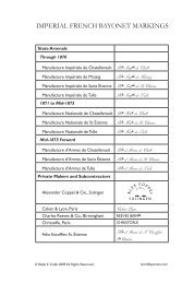
1,2?'6,554 ..Fiq.t.H. P. MAXIM.SCABBARD.APPLICATION fiLED JUNE 20, !917.Patented Aug. 20, 1918.10JOIIIIIIIIIIIII II II I,,I II I,.1--1IIIIITHE NOR HI$ ... t TE:IIS CO ,PHOTO.LITHC., WASH/HGtQfl, D.
'UNITED STACl~Es PATENT OFFICEQHIRAM PERCY MAXIl'II, OF HARTFORD, CONNECTICUT, ASSIGNOR TO THE MAXIMSILENCER COMPANY, OF HARTFORD, CONNECTICUT, A CORPOP~ATION OF CONNECTICUT.SCABBARD.1,276,5;)4. Specification <strong>of</strong> Letters Patent. Patented Aug·. 20, 1918.Application filed June 20, 1917. Serial No. 175,762.To all whom it may conceTn:I3e it kno\';n that I, HJR,DI PERCY JYL1.xnr,a citizen <strong>of</strong> the United States, residing at ·Hartford, in the county <strong>of</strong> Hartford and5 State <strong>of</strong> Connecticut, have invented certainne\Y and useful Improvements in Scabbards,<strong>of</strong> which the following is a specification.This in.-ention relates to <strong>scabbard</strong>s. Recentlythere has been a change in Federal10 equipmenL the result being that it is exceedinglydifficult, if not virtually impossihle,to suspend a British <strong>scabbard</strong> from aUnited States belt. The fundamental purpose<strong>of</strong> the invention is the provision <strong>of</strong>15 means <strong>of</strong> a simple and effective characterby which such a <strong>scabbard</strong> can be attachedto the belt at present in use in this countryand as easily separated, the invention moreespecially residing in the way in which the20 supporting hook is operatiYely associated~with the <strong>scabbard</strong>, this hook being capahle<strong>of</strong> detachable connection with the belt.In the drawings accompanying and formingpart <strong>of</strong> the present specification I have25 shown in detail a convenient form <strong>of</strong> embodiment<strong>of</strong> the inyention which to enablsthose skilled in the art to practice the samewill be set forth fully in the followingdescription. Obviously I do not restrictso myself to this particular disclosure; I maydepart therefrom in several particulars withinthe scope <strong>of</strong> the invention defined by theclaims follmYing said description.Referring to said clra·wings:35 Figures 1 and 2 are longitudinal views <strong>of</strong>the <strong>scabbard</strong> as seen at practically rightangles from each other.Fig. 3 is a transverse section on the line3-3 <strong>of</strong> Fig. 2.40 Like characters refer to like partsthroughout the several views.The <strong>scabbard</strong> is denoted by 2, and itsbody may be <strong>of</strong> any desirable shape. Thatsho>vn is practically the standard at present45 in use in Great Britain: being in the form<strong>of</strong> an elongated sleeve longitudinally tapering,open at one end and closed at the other.It may be <strong>of</strong> all metal or <strong>of</strong> composite form.From this as is inferred the <strong>scabbard</strong> may50 vary within reasonable limits.A <strong>scabbard</strong> such as that concisely describedis generally suspended from a belt,and as will be understood the present <strong>scabbard</strong>is not very well adapted for properconnection with a Uniterl States belt. and 55my fundamental purpose is to obviate thisobstacle and provide in a simple way forthe ready connection and disconnection <strong>of</strong>the <strong>scabbard</strong> with such a belt or analogouspart. The <strong>scabbard</strong> on one side externally 60there<strong>of</strong>, and near the open end, is providecl~with a block 3. This block may be connectedrigidly 'vith the <strong>scabbard</strong> in any desirablemanner. It may be brazed, ri veteclin place, or it can be spot welded. This 65block 3 as shown is furnished with projections,studs or rivets 4 spaced a part andextending from the outer fiat face <strong>of</strong> theblock or equivalent body 3. As illustratedthe block is <strong>of</strong> rectangular form, ancl its 70inner surface is curved to conform to theexternal surface <strong>of</strong> the rear vvall <strong>of</strong> themetallic upper part <strong>of</strong> the <strong>scabbard</strong>. Therivets 4 in the present case are integralwith the block 3. From this as will be ohi- 75ous, the block and the rivets can be easilymanufactured: in fact I have obtained themproperly by 'dropping or drop forging.After a part made up <strong>of</strong> the block and theprojecting rivets is produced, it can be tum- sobled if necessary to remove any slight surfaceimperfections and thereafter the exposedsurface <strong>of</strong> the block can be milledto smooth the same <strong>of</strong>f around the bases <strong>of</strong>the two rivets. This block 3 presents in 85effect a relatively stationary member <strong>of</strong> aclamp, the movable clamping member beingin the form <strong>of</strong> a washer as 5 which canbe cut from sheet stock and which has perforations6. These perforations are adapt- 90eel to receive the rivets 4. The means bvwhich the <strong>scabbard</strong> is suspended from a beltor the like involves a tab as 7. This tab ismade for example :from a necessary length<strong>of</strong> leather folded or doubled on itself to pre- 95sent a loop and having two sets <strong>of</strong> registeringperforations 8 which receive the rivets4, one portion <strong>of</strong> the tab, as will be clear,lying fiatwise against the fiat face <strong>of</strong> theblock 3 ancl the other portion <strong>of</strong> the tab 100heing superimposed npon the complementalpart. After the tab is in assembled relationwith the rivets 4, the rectangular washer isapplied by passing the integral rivets 4through the perforations 6 at ·which point 105the rivets are headed over so as to firmlyand substantially clamp the parts. The freeend <strong>of</strong> the tab 7 may have an eye 9 to re-
1,276,554ce~n· the supporting hook 10~ the hook bt~ingndnptetl to rngagr the belt or othnproper part.Thrrr is,, clecit1d ntlYantnge in pro1·i