UPS12-475 - NPS Telecom
UPS12-475 - NPS Telecom
UPS12-475 - NPS Telecom

Create successful ePaper yourself
Turn your PDF publications into a flip-book with our unique Google optimized e-Paper software.
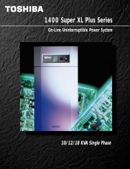
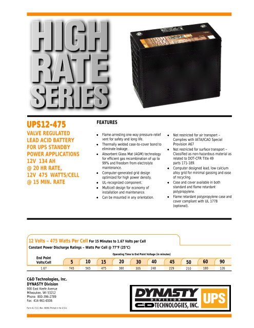
<strong>UPS12</strong>-<strong>475</strong>VALVE REGULATEDLEAD ACID BATTERYFOR UPS STANDBYPOWER APPLICATIONS12V 134 AH@ 20 HR RATE,12V <strong>475</strong> WATTS/CELL@ 15 MIN. RATEFEATURES• Flame-arresting one-way pressure-reliefvent for safety and long life.• Thermally welded case-to-cover bond toeliminate leakage.• Absorbent Glass Mat (AGM) technologyfor efficient gas recombination of up to99% and freedom from electrolytemaintenance.• Computer-generated grid designoptimized for high power density.• UL-recognized component.• Multicell design for economy ofinstallation and maintenance.• Can be mounted in any orientation.• Not restricted for air transport –Complies with IATA/ICAO SpecialProvision A67• Not restricted for surface transport –Classified as non-hazardous material asrelated to DOT-CFR Title 49parts 171-189.• Computer designed lead, low calciumalloy grid for minimal gassing and easeof recycling.• Case and cover available in bothstandard and flame retardantpolypropylene.• Flame retardant polypropylene case andcover compliant with UL 1778(optional).12 Volts – <strong>475</strong> Watts Per Cell For 15 Minutes to 1.67 Volts per CellConstant Power Discharge Ratings – Watts Per Cell @ 77°F (25°C)End PointVolts/CellC&D Technologies, Inc.DYNASTY Division900 East Keefe AvenueMilwaukee, WI 53212Phone: 800-396-2789Fax: 414-961-6506Operating Time to End Point Voltage (in minutes)5 10 15 20 30 40 45 50 60 901.67 745 565 <strong>475</strong> 380 305 248 229 210 180 126Form 41-7111 (Rev. 08/99) Printed in the U.S.A.
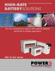
<strong>UPS12</strong>-<strong>475</strong>1.29[32.8]1/4-20 UNC6.76[171.7]10.81[274.5]10.93[277.7]1.22[31.1]13.57[344.7]<strong>UPS12</strong>-<strong>475</strong> – Specifications12.746.73[323.6] [171.0]0.12[3.2]*All dimensions in inches and (millimeters). All dimensions are for reference only.Contact a C&D Representative for complete dimensional information.CellsPer UnitVoltagePer Unit Weight Electrolyte6 12.84 100 lbs.45 kgAbsorbed H 2SO 4SG = 1.300MaximumDischarge CurrentShort CircuitCurrent800 Amps 5000 Amps@ 0.1 sec.Ohms Imped.60 Hz (Ω)0.0023 OhmsCapacityOperating Temperature RangeNominalRangeOperating Temperature<strong>475</strong> watts per cell at the 15 minute rate to 1.67 volts per cell134 Ah @ 20 hr. rate to 1.75 volts per cell @ 77˚ F (25˚ C)122 Ah @ 10 hr rate to 1.80 volts per cell @ 20˚ C (68˚ F)at 77˚ F (25˚ C).D ischarge; - 40˚ F (-40˚ C) to +160˚ F (71˚ C) , Charge;-10˚ F(-23˚ C) to +140˚F (60˚)(with temperature compensation)+74˚ F (23˚ C) to +80˚ F (27˚ C)F loat Charging Voltage13.5 to 13.8 VDC/unit Average at 77˚ F (25˚ C) .RecommendedCurrent LimitConstant Power Discharge Ratings – Watts Per Cell @ 77°F (25°C)End PointMaximum ChargingEqualization and Cycle ServiceCharging VoltageC/5 amperes (27 amperes @ 100% depth of discharge)14.4 to 14.8 VDC/unit Average at 77˚ F (25˚ C).Maximum A C Ripple (Charger) 0.5% RMS or 1.5% P-P of float charge voltage recommended for best results.Maximum voltage allowed = 1.4% RMS (4% P-P)Maximum current allowed = 6.7 amperes (C/20)SelfDischargeVolts/Cell 5 10 15 20 30 40 45 50 60 901.75 685 515 430 365 300 240 220 200 175 1251.70 725 555 460 375 302 245 226 208 178 1261.67 745 565 <strong>475</strong> 380 305 248 229 210 180 1261.65 750 575 480 382 308 250 230 211 182 1261.60 780 590 485 385 310 252 232 212 185 127Constant Current Discharge Ratings – Amperes @ 77°F (25°C)Dynasty UPS batteries may be stored for up to 6 months at 77˚ F (25˚ C) and thena freshening charge is required. For higher temperatures the time interval will beshorter.A ccessoriesInter unit connectors, racks and cabinet systems are available.T erminal"L" terminal with 0.28" clearance hole to accept 0.25" (6mm) bolt.T erminal Hardware Initial Torque Threaded copper insert.T erminal Hardware Annual Retorque 110 in.-lbs. (12.4 N-m)Operating Time to End Point Voltage (in minutes)Operating Time to End Point Voltage (in hours)End PointVolts/Cell 1 2 3 5 8 10 12 241.90 70.4 42.2 30.8 20.2 13.4 11.03 9.36 4.961.85 79.3 46.8 33.9 22.1 14.6 11.90 10.20 5.401.80 84.9 49.3 35.3 23.0 15.2 12.40 10.59 5.601.75 88.3 50.5 36.3 23.4 15.9 12.74 10.74. 5.68Note: Batteries to be mounted with 0.5 in. spacing minimum and free air ventilation. Specifications subject to change without notification.