Digital Temperature Controller DPC III
Digital Temperature Controller DPC III
Digital Temperature Controller DPC III

Create successful ePaper yourself
Turn your PDF publications into a flip-book with our unique Google optimized e-Paper software.
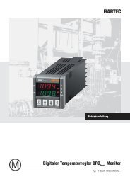
<strong>DPC</strong> <strong>III</strong> Type 17-8821-4.2222303.00 Operating InstructionsOperating Instructions<strong>Digital</strong> <strong>Temperature</strong> <strong>Controller</strong> <strong>DPC</strong> <strong>III</strong>Type 17-8821-4.2222303.00
<strong>DPC</strong> <strong>III</strong> Type 17-8821-4.2222303.00 Operating InstructionsReservationTechnical data subject to change without notice.Changes, errors and misprints do not justify any claims for damages.
<strong>DPC</strong> <strong>III</strong> Type 17-8821-4.2222303.00 Operating Instructions5. Adjustment of the two-position controller5.1. Setpoint inputs with the function:„Fast setting“ (factory setting)Example: Setpoint (SP1 = 50 °C)Low alarm (AL1L = 10 °C)High alarm (AL1H = 100 °C)5.2. Altering the hysteresisSSet25SP 1Basic Displayauto025OPErBasic Display2sSP 1auto50>SPSSetAL1Lauto5>PAnAL1LSSetAL1Hautoauto109999>rEGSSetContAL1HSSetauto100HSEtSSetHSEtauto2HSEtauto3SSetHSEt3s4
<strong>DPC</strong> <strong>III</strong> Type 17-8821-4.2222303.00 Operating Instructions6. Mode of operation of the controller6.1. Function diagram two-position controller (factory setting)Setpoint(SV)HysteresisHSEt = 2KActual value(PV)TimeOUT 1ON6.2. Function diagram PID-controllerϑSetpoint(SV)Actual value(PV)TimeOUT 3ONct ct ct ct ct ct ct ctct Factory setting = 6 sec.ct = Cycle time6.3. Function diagram digital inputHigh alarmSetpointLow alarmActual value(PV)TimeHigh alarmLow alarmDIG.IN 25 65 6OUT 113 1713 17OUT 220 2220 225
<strong>DPC</strong> <strong>III</strong> Type 17-8821-4.2222303.00 Operating Instructions7. Use as a PID controller: This type of control can be set in the following three steps:Step 1Define the logic output (Out 3) as a regulatingoutputStep 2Select the PID type of controlStep 3If you so wish, the factory-set standard PIDparameters can be determined automaticallyby means of AUTOTUNING and saved in thedevice.25OPErBasic Display2s25OPErBasic Display2s25OPErBasic Display2s>SP>SPConF>PAn>InPOFF>rEGSSet>OutSSettunEContO1F25SSetContautoO:FAO2Fmax.12hContautoPidO3FSSetSSetContO3FautoOFF3sO3Fauto!rEGSSetO3F3s6
<strong>DPC</strong> <strong>III</strong> Type 17-8821-4.2222303.00 Operating Instructions8. Operation, MaintenanceThe owner/managing operator of an electricalsystem must ensure that the operating equipmentis in proper condition, operate it in accordancewith instructions, monitor it and carry outpreventative and corrective maintenance.Each piece of electrical equipment must beselected according to its suitability.Before being put into operation again, theapplicable laws and directives must be observed.The safety instructions given must be followedbefore maintenance work is done or failuresrectified.9.2. <strong>Temperature</strong> alarmsThe floating relay output OUT 2 is factory-set as a group alarm output in the „normally energised /NC = normally closed“ mode of operation. Accordingly, the contact remains closed (relay activated)as long as there isn’t any fault. This principle of action allows wire breakage and power failure to bedetected.The following shows this effect in detailϑ Actual value(PV)AL1HAL1LHysteresisHAL1 = 1KHysteresisHAL1 = 1K9. Alarm management9.1. Measuring circuit monitoringThe connected temperature sensor system(Pt100) is monitored for the following faults:LowalarmON■■■Short-circuit sensorInterruption sensorSensor undershooting or overshooting ofthe measuring rangeHighalarmONONWhen one of these faults occurs, the devicereacts as follows:OUT 220 2220 22■■■Contact load relay (OUT 1) opensContact alarm relay (OUT 2) opensLogic output (OUT 3) switches offMainsvoltageONON10. Technical DataTypes of controlTwo-position (ON/OFF), PIDSerial interfaceOnly Version Monitor:RS485 with Modbus RTU protocolDisplay1-line, red display (h = 12 mm, 4 digit);some green status LEDsMeasuring and display accuracy0.5 %Ambient temperature range0°C up +50 °CStorage temperature-10°C up +60°CEnclosurePlastic UL 94 V0TerminalsTerminal screws; max. 2.5 mm²(see also the Chapter on Assembly)DimensionsLength:70 mmWidth:84 mmMounting depth: 60 mmInstallation dimensions4 DIN horizontal pitches (45 x 70 mm)Protection classIP 40 (front plate)Installation positionHorizontal on TS 35 railWeightca. 230 g7
<strong>DPC</strong> <strong>III</strong> Type 17-8821-4.2222303.00 Operating Instructions11. Electrical dataVoltage supply (see type label)AC 100 to 240 V, +/-10 %, 50/60 Hz or AC/DC 24 V, +/-10 %<strong>Digital</strong> inputsFloating contacts requiredOutput 1Relay (normally-open contact)AC 250 V 16A (ohmic load)Output 2Relay (change-over)AC 250 V 8A (ohmic load)Output 3Logic output for SSR control(DC 11 V/20 mA)Power consumptionMax. 5 VAMeasuring circuitU max =5 V, I max = 0.15 mAElectrical safetyEN 60730-1, -A1, -A12, -A13, -A14EN 60730-2-9, -A1, -A2, -A11, -A12Electromagnetic compatibilityEN 61326-112. Electrical Connection Device ConnectionsTerminals 1, 3Terminals 4, 5, 6Terminals 7, 8, 9Mains connection<strong>Digital</strong> inputsRS485 interfaceTerminals 13, 17 Floating normally-open contact OUT 1(Regulating output for ON/OFF control)Terminals 20, 22, 24 Floating change-over OUT 2(Group fault alarm)Terminals 18, 19 Logic output for SSR OUT 3(Regulating output for PID control)Terminals 10, 11, 12Sensor connection for:■BARTEC resistance thermometerPt100 Ex, (2 or 3-conductor version)■ BARTEC resistance thermometerPt100 M, (2 or 3-conductor version)■ Thermocouple J, K, S■Voltage signal 0 to 50 mV0 to 60 mV, 12 to 60 mVNote:In the Pt100 two-conductor version terminals 2 and 3 must be bridged – as thesensor will otherwise malfunction!12.1. Wiring diagrams <strong>DPC</strong> <strong>III</strong> Standard<strong>DPC</strong> <strong>III</strong> standard as two-position controller (ON/OFF)Supply voltage A-B see type label<strong>DPC</strong> <strong>III</strong> Standard PID <strong>Controller</strong>Supply voltage A-B see type labelLNPEAB-F1-F2Service anRohrleitung(z.B. Dampfspülung)Service atpipe (e.g. steamcleaning process)Messwartecontrol station-X1 1 2 3LNPEAB-F1-F2Service anRohrleitung(z.B. Dampfspülung)Service atpipe (e.g. steamcleaning process)Messwartecontrol station-X1 1 2 3-S113-S1131414-N11 3 4 5 624 20 22SUPPLY-N11 3 4 5 624 20 22SUPPLYDIG DIGIN 1 IN 2OUT 2(Alarm)DIG DIGIN 1 IN 2OUT 2(Alarm)17-8821-4*2222303000<strong>DPC</strong> <strong>III</strong> StandardTC/mVOUT 1Pt100OUT 3 (Load)SSR (Crtl)+ -17-8821-4*2222303000<strong>DPC</strong> <strong>III</strong> StandardTC/mVOUT 1Pt100OUT 3 (Load)SSR (Crtl)+ -10 11 1218 19 13 17-B2-E110 11 1218 19-B2 -V1 + -13 17-E1Pt100Pt100SSR8
<strong>DPC</strong> <strong>III</strong> Type 17-8821-4.2222303.00 Operating Instructions12.2. Wiring diagrams <strong>DPC</strong> <strong>III</strong> Monitor<strong>DPC</strong> <strong>III</strong> Monitor as two-position controller (ON/OFF)<strong>DPC</strong> <strong>III</strong> Monitor as PID-<strong>Controller</strong>Supply voltage A-B see type labelSupply voltage A-B see type labelLNPEAB-F1-F2Service anRohrleitung(z.B. Dampfspülung)Service atpipe (e.g. steamcleaning process)Messwartecontrol station-X1 1 2 3LNPEAB-F1-F2Service anRohrleitung(z.B. Dampfspülung)Service atpipe (e.g. steamcleaning process)Messwartecontrol station-X1 1 2 3-S113RS485-S113RS4851414-N11 3 4 5 6 78924 20 22SUPPLYB GND ARS485-N11 3 4 5 6 78924 20 22SUPPLYA B GNDRS485DIG DIGIN 1 IN 2OUT 2(Alarm)DIG DIGIN 1 IN 2OUT 2(Alarm)17-8821-4*2222303200<strong>DPC</strong> <strong>III</strong> MonitorTC/mVOUT 1Pt100OUT 3 (Load)SSR (Crtl)+ -17-8821-4*2222303200<strong>DPC</strong> <strong>III</strong> MonitorTC/mVOUT 1Pt100OUT 3 (Load)SSR (Crtl)+ -10 11 1218 19 13 17-B2-E110 11 1218 19-B2 -V1 + -13 17-E1Pt100Pt100SSRInterface wiring when connecting several devices through the RS485HOST(PC/PLC)ABGNDshieldRt120 ohmRS485InterfaceA B GND18 17 16A B GND A B GND18 17 16 18 17 16<strong>DPC</strong> <strong>III</strong>Monitorno.1<strong>DPC</strong> <strong>III</strong>Monitorno.2<strong>DPC</strong> <strong>III</strong>Monitorno. n9
<strong>DPC</strong> <strong>III</strong> Type 17-8821-4.2222303.00 Operating Instructions13. List of ParametersDisplay Display Description Levels/ Factory Version VersionParametername Parametergruppe Setting range setting Standard MonitorSP 1 S P Setpoint 1 heating (regulating output) -1999 °C to +9999 °C 0 °C AL1L AL1 Setpoint low alarm (alarm output) -1999 °C to AL1H 5 °C AL1H AL1 Setpoint high alarm (alarm output) AL1L to 9999 °C 9999 °C Add SEr Device address for serial interfacec 0 to 255 1 bAud SEr Transmission speed of the serial interface 1200 / 2400 / 9600 / 9600 19.2 / 38.4PACS SEr Access control through serial port LoCl/LorE LorE “LoCl“ = can only be programmed withkeypad; LorE = can be programmed withkeypad and interface14. Fault signals/fault clearanceDisplay of the fault in the display Description Fault clearance procedures****uuuuooooErAtnoAtInterruption sensorThe temperature measured is lower thanthe sensor limit level.The temperature measured is higher thanthe sensor limit level.Autotuning cannot be carried out.Autotuning could not be repeated withina period of 12 hours.Check and if necessary replace the sensor. The fault signal isautomatically reset once the fault has been rectified.Check and if necessary replace the sensor. The fault signal isautomatically reset once the fault has been rectified.Check and if necessary replace the sensor. The fault signal isautomatically reset once the fault has been rectified.Set the controller to OFF and then activate the automatic regulation(rEG) to eliminate the fault. Repeat autotuning once the cause of thefault has been found.Check sensor and heating circuit for operability and then repeatautotuning.15. Type DesignationTypeDescriptionExample type label17-8821-4722/2230 3000 <strong>DPC</strong> <strong>III</strong> Standard; AC 100 to 240 V17-8821-4C22/2230 3000<strong>DPC</strong> <strong>III</strong> Standard; AC/DC 24 V17-8821-4722/2230 3200 <strong>DPC</strong> <strong>III</strong> Monitor; AC 100 to 240 V, with RS48517-8821-4C22/2230 3200<strong>DPC</strong> <strong>III</strong> Monitor; AC/DC 24 V, with RS48516. Service addressBARTEC GmbHGermanyMax-Eyth-Straße 16D-97980 Bad MergentheimPhone: +49 7931 597-0Fax.: +49 7931 597-11910
<strong>DPC</strong> <strong>III</strong> Type 17-8821-4.2222303.00 Operating Instructions11
<strong>DPC</strong> <strong>III</strong> Type 17-8821-4.2222303.00 Operating Instructions
<strong>DPC</strong> <strong>III</strong> Type 17-8821-4.2222303.00 Operating Instructions
<strong>DPC</strong> <strong>III</strong> Type 17-8821-4.2222303.00 Operating InstructionsBARTEC GmbHGermanyMax-Eyth-Straße 1697980 Bad MergentheimPhone: +49 7931 597-0Fax: +49 7931 597-119info@bartec.dewww.bartec-group.com11-8821-7D0004-04/09-BARTECWerbeAgentur-275826_UK