Product advantages Mobile Crane LTM 1200/1 Max. lifting capacity
Product advantages Mobile Crane LTM 1200/1 Max. lifting capacity
Product advantages Mobile Crane LTM 1200/1 Max. lifting capacity

Create successful ePaper yourself
Turn your PDF publications into a flip-book with our unique Google optimized e-Paper software.
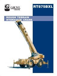
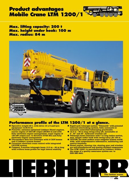
<strong>Product</strong> <strong>advantages</strong><strong>Mobile</strong> <strong>Crane</strong> <strong>LTM</strong> <strong>1200</strong>/1<strong>Max</strong>. <strong>lifting</strong> <strong>capacity</strong>: 200 t<strong>Max</strong>. height under hook: 100 m<strong>Max</strong>. radius: 84 mPerformance profile of the <strong>LTM</strong> <strong>1200</strong>/1 at a glance.● Operative weight 60 t, with drive 10 x 8 and tyreequipment 16.00 R 25● Powerful, emission-optimized Liebherr Diesel engines,carrier engine of 400 kW output (EURO 3) and withfully electronic engine management, crane engine of180 kW output (acc. to directive 97/68 EU) and fullyelectronic engine management● Ultramodern data bus technique with 2 CAN bussesand 3 Liebherr system busses● Covenient electronic crane control with integratedLICCON system● Compact, 6-section telescopic boom 13.3 m – 60 m longwith oviform boom profile for high lateral stability● Rapid-cycle telescopic system “Telematik” with patentedinternal interlocking system, fully automatic ormanually controlled telescoping practicable● 12.2 m – 36 m long swing-away jib, mountable at0°, 20° and 40°, hydraulic erection aid● Telescopic boom extension with 7 m long lattice section,max. height under hook with swing-away jib 100 m● LICCON, the most modern crane computer system worldwide,with comprehensive informative, monitoring andcontrol functions● Diesel engine, slewing rim, slewing gear and winchesare self-manufactured and quality-checked components● The <strong>LTM</strong> <strong>1200</strong>/1 is manufactured by Liebherr withinthe scope of a quality assurance system acc. toDIN ISO 9001The better crane.
Comfortable driving cabin ofoutstanding functionality. Modern and comfortable driver’s cab of high functionalityand convincing design Ergonomically arranged operating and display elementsfor safe and convenient handling at continuos operation Digital display and keyboard units interconnected withthe function blocks by data bus technique Air-cushioned driver’s and co-driver’s seats, headrests,driver’s seat with pneumatic lumber support Safety belts for driver and co-driver Height and inclination adjustable steering wheel Heated and electrically adjustable rear mirrors Side panes with electric window lilfters 3 windscreen wipers with automatic wiper/washersystem and intermittent control Delayed disconnection of interior lighting Various racks and boxes Radio preparationComfortable crane cabin ofoutstanding functionality. Spring-mounted and hydraulically cushioned craneoperator’s seat with pneumatic lumber support andheadrest Operator-friendly armrest-integrated controls, verticallyand horizontally adjustable master switch consoles andarmrests, ergonomically adjustable operating consoles Ergonomic control levers with integrated winch rotationand slewing signalling device Modern supporting base with integrated LICCONmonitor, display of all essential operating data on theLICCON screen Green tinted heat-isolating front and side window panes 3 windscreen wipers with automatic wiper/washersystem and inermittent control Delayed disconnection of interior lighting Various racks and boxes Radio preparation 1 work projector 70 Watt on the cabin front5
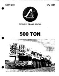
The electric and electronic components are interconnectedby the latest data bus transmission technique Instead of the traditional electric wiring, the datatransmission to the individual function blocks is performeddigitally just by a few data cables, thus improvedreliability due to essentially less contacts Self-manufactured Liebherr bus systems, specially adaptedto the requirements of a mobile crane Carrier engine, AS-TRONIC gear, intarder and enginebrake, as an integrated automated power train, arecontrolled via a CAN data bus. The fully electronic drivemanagement reduces fuel consumption and improves theexhaust gas emission The crane engine is controlled via a CAN data bus The carrier and crane electric systems, including allcockpit functions, the outrigger system and the boomsensor system are interconnected by 3 Liebherr systembusses The activation of the function blocks is realized byI/O modules, the programming of which is performed viathe Liebherr system busses. The control intelligence isintegrated into the LICCON central unit Comprehensive diagnostic facilities, quick error detection,operator error display Test programs for the functional test of the keyboard anddisplay unit as well as for the check of the control devicesfor engine and gear management, Liebherr additionalbrake system, hydraulic ventilator, hydraulic suspensionand outrigger control panels The new data bus technique clearly contributes to anincrease in functionality and efficiency of the mobilecrane1617LSB 318LSB 214Legend:LSB - Liebherr System Bus 1LSB - Liebherr System Bus 2LSB - Liebherr System Bus 3CAN - BusSCI - Serial Communication Interface1 control functions, compressed-air control of brakes1a Instrument – keyboard unit in driver’s cab2 Input/output modules for differential locks, displayfunctions2a Instrument – keyboard unit in driver’s cabin3 Input/output module for outrigger system – right3a Control unit for outriggers – right4 Input/output module for outrigger system – left4a Control unit for outriggers – left5 Input/output module for engine brake, cruise controller,speed setter, electronic control of Diesel engine(steering column switch right) and ZF AS-TRONICpower shift gear6 Control of automated ZF power shift gear6a Control of intarder7 Control of injection pump – Liebherr Dieselengine/carrier8 Slewing sensor within slipring unit9 Connection of Liebherr System Bus (LSB 1, 2, 3)10 LICCON central unit11 LICCON monitor in crane cabin12 Length sensor and cable drum/energy cable forinterlocking gripper/telescopic boom13 Inductive sensor (12 x)14 Angle sensor on base section15 Cable drum for items 16, 17 and 18 for swing-away jib16 Wind sensor (optional)17 Hoist limit switch18 Angle sensor19 Input/output module for electronic control of Dieselengine/superstructure, air flap, ventilator clutch,exhaust flap20 Control of injection pump – Liebherr Diesel engine/cranesuperstructure21 Control lever22 Pressure sensor (2) for output magnet2015CAN-Bus6a 671319CAN-Bus22921210LSB 31a13a 3 821 21LSB 12a54 4aData bus technique improves functionality and efficiency.67
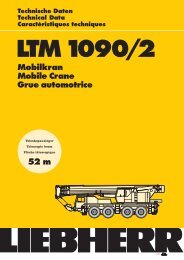
60 m56.3 m52 m47.7 mLifting loads – precise and safe.● 6-section, 60 m long telescopic boom with rounded,oviform bottom shell for maximum lateral stability● Optimal utilization of the telescopic boom through amultitude of telescoping variants● 12.2 m – 22 m long biparted swing-away jib, extendableto 29 m and 36 m● Swing-away jib mountable at 0°, 20° and 40°, hydraulicfitting aid● Telescopic boom extension 7 m, thus base section fixingpoint of swing-away jib higher by 7 m● Easy and quick re-reeving of the hoist rope due to theself-locking rope dead end connection● Load hook with self-locking rope dead end connection,cylindrically shaped hook for easy displacement byrolling on hard surface43.4 m36 m39.1moviform boom profile34.8 m20°40°30.5 m26.2 m7 m21.9 m56.3 m52 m17.6 m47.7 m43.4 m13.3 m13.3 m8
LICCON computer system withconvenient applicationprograms● Standard application programs: Safe load indicator(SLI), configuration program with configuration image,operating program with operating image, telescopingprogram with telescoping image, supporting forcedisplay, control parameter program, test system; andas an option, the work area limitation and the LICCONwork planner● Setting of crane configuration by convenient interactivefunctions● Safe and reliable acknowledgement of the craneconfiguration set● Representation of all essential data by graphic symbolson the operating image● Integrated wind speed control● Reliable cut-off device in the event of exceeding thepermissible load moments● Safe working load values for any intermediate boomlength● Winch indications for ultra-precise <strong>lifting</strong> and loweringof the loadLICCON-assisted telescopingsystem● Telescoping by single-stage hydraulic ram withhydraulic driving tenons (patented internal interlockingsystem)● Telescoping procedure controllable by convenientoperator’s guide on the monitor, precise approach ofinterlocking positions● Telescopable loads are displayed on the LICCONoperating image● Rapid-cycle telescoping system with “automatic mode”,i.e. fully automatic telescoping of the boom to the desiredlength● Particularly compact and light-weight telescopingsystem, thus increased <strong>lifting</strong> capacities specially withlong booms at large radii● Automatic cushioning in end positions duringtelescoping and retracting for the preservation of thestructural members9
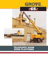
2.985.33The LICCON work planner. The LICCON work planner consists of a softwareprogram on diskettes for planning, simulation anddocumentation of crane applications on the monitor The 2-D planner allows to draw buildings, to write textsand to represent a crane model true to scale includingits entire motions within a fictional construction site The work planner enables the preparation of moretransparent offers, it facilitates the briefing of the craneoperators and it can be run on a laptop at the constructionsiteMounting of counterweight –just a matter of minutes. Counterweight variants of 12 t, 24 t, 36 t, 45 t,57 t and 69 t Ballasting controlled from the crane cabin Quick ballasting due to a new “keyhole” system Ballast rams fixed-mounted to the superstructure Compact counterweight dimensions, e.g. 45 tcounterweight of 3 m m width only12 tR = 4.859 t12 t12 t12 t45 t12 t11
The LICCON test system The test system assists the servicing personnel inquickly localizing errors of the sensor system of thecrane without needing any further measuringinstruments Convenient interactive functions permit the observationof all in- and outputs of the general system by differentdisplays on the monitor even during crane operation.It equally visualizes the allocation of the individualsensors to the system as well as their function and theterminals concerned in the control cabinet The table of contents enables the display on the monitorof the contents and the state of development of theprogram modules as well the load charts The service starts on the monitor, error detection becomesa matter of secondsThe LICCON work arealimitation system. It relieves the crane operator, especially in situationswhere the handling of loads requires his full attention,by controlling the work area limits. Work areas can berestricted by buildings, bridges, roofs, high-tensionlines, pipe lines or adjacent cranes. The automatic workarea limitation system (optional) can easily beprogrammed. Four different limitation functions arepracticable: Height limitation of the pulley head Radius limitation Slewing angle limitation Limitation of edges10
Electric/electronic PLC crane control and testsystem. Control of the winches, slewing gear as well as luffingand telescoping motions via the LICCON computersystem (PLC control) Four working motions can be performed independentof one another Speeds of hoisting/lowering, luffing and slewingpreselectable by 5 steps Very short response rate when initiating the cranemotions Hoist gear and slewing gear are operating within a“closed oil circuit”. This enables particularly precisehoisting, lowering or slewing of the load. Moreover, thepotential energy generated during the lowering of aload is not converted into heat but can be re-employedfor a second motion. This offers the particular advantagein saving fuel and reduced thermal exposure of the oilthan in an open circuit. Functional test of all essential components by theLICCON test systemLICCONdisplayscreensingleactiontelescopingram withhydraulicinterlockingdeviceluffing ramcontrol leversenginecontrolcontrol blockLiebherr hoistwinch ItransmitterssensorsLICCONcontroldouble variabledisplacementpumpLiebherr hoistwinch II3 variabledisplacement pumpsLiebherr Diesel engine D 924 TI- ELiebherrslewing gearOptional features extend the application spectrum andincrease comfort and safety.On the carrier Auxiliary heater Thermo 90 S with engine pre-heating Eddy-current-brake Supporting pressure indication on carrier and in craneoperator’s cabin Stow-away box for sling gear and stand timber Air-conditioning system Trailer coupling D12/D19 Radio preparation Seat heating for driver’s and co-driver’s seat Fog lamps Casset radio setOn crane superstructure/telescopic boom 2nd hoist gear Auxiliary heater Thermo 90 S with engine pre-heating Air-conditioning system Seat heating Work area limitation Aircraft warning light Work projector 1 x 70 W on cabin roof Work projector 2 x 150 W on boom base section,electrically adjustable Whip line erection jib GSM module for remote diagnostics Radio preparation Cassette radio setFurther optional features by request.Subject to modification. TP 313. 01.01Please contactLIEBHERR-WERK EHINGEN GMBH, Postfach 1361, D-89582 EhingenPhone (0 73 91) 5 02-0, Telefax (0 73 91) 5 02-33 99www.lwe.liebherr.de, e-mail: info@lwe.liebherr.com