
Create successful ePaper yourself
Turn your PDF publications into a flip-book with our unique Google optimized e-Paper software.
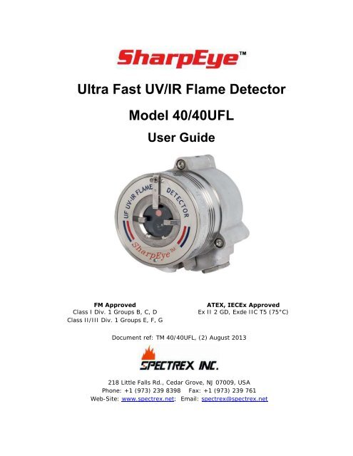
iiSharpEye TM Ultra Fast UV/IR Flame Detector User Guide
Legal NoticeThe SharpEye Optical Flame Detector described in this document is the property of <strong>Spectrex</strong>,<strong>Inc</strong>.No part of the hardware, software or documentation may be reproduced, transmitted,transcribed, stored in a retrieval system or translated into any language or computer language,in any form or by any means, without prior written permission of <strong>Spectrex</strong>, <strong>Inc</strong>.While great efforts have been made to assure the accuracy and clarity of this document,<strong>Spectrex</strong>, <strong>Inc</strong>. assumes no liability resulting from any omissions in this document, or frommisuse of the information obtained herein. The information in this document has been carefullychecked and is believed to be entirely reliable with all of the necessary information included.<strong>Spectrex</strong> <strong>Inc</strong>. reserves the right to make changes to any products described herein to improvereliability, function, or design, and reserves the right to revise this document and makechanges from time to time in content hereof with no obligation to notify any persons ofrevisions or changes. <strong>Spectrex</strong>, <strong>Inc</strong>. does not assume any liability arising out of the applicationor any use of any product or circuit described herein; neither does it convey license under itspatent rights or the rights of othersWarning: This manual should be read carefully by all individualswho have or will have responsibility for using, maintaining orservicing the product.The Detector is not field-repairable due to the meticulousalignment and calibration of the sensors and the respectivecircuits. Do not attempt to modify or repair the internal circuitsor change their settings, as this will impair the system'sperformance and void the <strong>Spectrex</strong>, <strong>Inc</strong>. Product warranty.WarrantySPECTREX INC. Agrees to extend to Purchaser/Distributor a warranty on the SPECTREXsupplied components of the SharpEye products. SPECTREX warrants to Purchaser/Distributorthat the products are free from defects in materials and workmanship for a period of five (5)years, commencing with the date of delivery to Purchaser/Distributor. SPECTREX expresslyexcludes damage incurred in transit from the factory or other damage due to abuse, misuse,improper installation, or lack of maintenance or “Act of God” which are above and beyond itscontrol. SPECTREX will, upon receipt of any defective product, transportation prepaid, repair orreplace it at its sole discretion if found to have been defective when shipped. Said repair orreplacement is SPECTREX’S sole liability under this warranty and SPECTREX’S liability shall belimited to repair or replacement of the component found defective and shall not include anyliability for consequential or other damages. The customer is responsible for all freight chargesand taxes due on shipments both ways. This warranty is exclusive of all other warrantiesexpress or implied.Legal Noticeiii
SharpEye TM Ultra Fast UV/IR Flame Detector User GuideRelease HistoryRev Date Revision History Prepared by Approved by0 October 2012 First Release Ian Buchanan Eric Zinn1 March 2013 Second Release Ian Buchanan Eric Zinn2 August 2013 Third Release Ian Buchanan Eric Zinniv
About this GuideThis guide describes the SharpEye Model 40/40UFL Flame Detector and itsfeatures and provides instructions on how to install, operate and maintainthe detector.This guide includes the following chapters and appendixes:Chapter 1, Introduction, provides a general overview of the product,principles of operation, and performance considerations.Chapter 2, Installing the Detector, describes how to install thedetector including preparations before installation, wiring and modesettings.Chapter 3, <strong>Operating</strong> the Detector, describes how to power-up andtest the detector. The chapter also lists safety precautions you shouldtake when operating the detector.Chapter 4, Maintenance and troubleshooting, describes basicmaintenance procedures, and troubleshooting and support procedures.Appendix A, Technical Specifications: Lists the detectors technicaland other specifications.Appendix B, Wiring Instructions, lists the wiring instructions forconnecting the detector and also provides examples of typical wiringconfigurations.Appendix C, RS-485 Communication Network, provides an overviewof the RS-485 communications network.Appendix D, Accessories, describes the accessories available for thedetector.About this Guidev
SharpEye TM Ultra Fast UV/IR Flame Detector User GuideAbbreviations and AcronymsAbbreviationATEXAWGBITEMCEOLFOVHARTIADIECExIPAIRJP5LatchingLEDLPGmAMODBUSN.C.N.O.N/ANFPANPTSILUNCVACMeaningAtmosphere ExplosivesAmerican Wire GaugeBuilt In TestElectromagnetic CompatibilityEnd of LineField of ViewHighway Addressable Remote TransducercommunicationprotocolImmune at Any DistanceInternational Electrotechnical Commission ExplosionIsopropyl AlcoholInfraredJet FuelRefers to relays remaining in the ON state even after theON condition has been removedLight Emitting DiodeLiquefied Petroleum GasMilliAmps (0.001 amps)Master-slave messaging structureNormally ClosedNormally OpenNot ApplicableNational Fire Protection AssociationNational Pipe ThreadSafety Integrity LevelUnified Coarse ThreadVolts Alternating CurrentviAbbreviations and Acronyms
Table of ContentsUltra Fast UV/IR Flame Detector Model 40/40UFL User Guide ......................... iLegal Notice .................................................................................................... iiiWarranty ........................................................................................................ iiiRelease History ............................................................................................... ivAbout this Guide .............................................................................................. vAbbreviations and Acronyms ............................................................................. vi1 Introduction .............................................................................................. 11.1 Overview .............................................................................................. 11.2 Model and Types .................................................................................... 21.3 Features and Benefits ............................................................................. 41.4 Principles of Operation ............................................................................ 41.4.1 Detection Principles .......................................................................... 41.4.2 Heated Optics .................................................................................. 51.4.3 HART Protocol ................................................................................. 61.4.4 RS-485 Modbus ............................................................................... 61.4.5 Product Certification ......................................................................... 61.5 Performance Considerations .................................................................... 81.5.1 Detection Sensitivity ........................................................................ 81.5.2 Cone of Vision ................................................................................. 91.5.3 False Alarms Prevention ................................................................... 111.5.4 Visual Indicators ............................................................................. 121.5.5 Output Signals ................................................................................ 131.5.6 Detector Status .............................................................................. 141.5.7 Auxiliary Relay as End-of-Line Resistor .............................................. 151.6 Internal Detector Tests .......................................................................... 151.6.1 Continuous Feature Test .................................................................. 151.6.2 Built-In-Test (BIT) .......................................................................... 162 Installing the Detector ............................................................................ 192.1 General Guidelines ................................................................................ 192.2 Unpacking the Product ........................................................................... 202.2.1 Checking the Product Type ............................................................... 202.3 Required Tools ...................................................................................... 212.4 Certification Instructions ........................................................................ 22Table of Contentsvii
SharpEye TM Ultra Fast UV/IR Flame Detector User Guide2.5 Installation Cables ................................................................................ 232.5.1 Conduit Installation ......................................................................... 232.6 Installing the Tilt Mount (part no. 40/40-001) .......................................... 242.6.1 Tilt Mount Specifications .................................................................. 252.6.2 Tilt Mount Assembly ........................................................................ 252.7 Connecting the Detector ........................................................................ 272.7.1 Verifying the Detector Wiring ........................................................... 282.8 Configuring your Detector ...................................................................... 292.8.1 Alarm Delay ................................................................................... 302.8.2 Address Set-up ............................................................................... 302.8.3 Function Set-up .............................................................................. 312.8.4 Heated Optics ................................................................................. 313 <strong>Operating</strong> the Detector ............................................................................ 333.1 Powering Up ......................................................................................... 333.2 Safety Precautions ................................................................................ 343.2.1 Default Functions Settings ............................................................... 343.3 Testing Procedures ................................................................................ 353.3.1 Automatic BIT Test ......................................................................... 353.3.2 Testing with Fire Simulator Model 20/20-311 ..................................... 354 Maintenance and Troubleshooting ........................................................... 374.1 Maintenance ......................................................................................... 374.1.1 General Procedures ......................................................................... 374.1.2 Periodic Procedures ......................................................................... 384.1.3 Keeping Maintenance Records .......................................................... 384.2 Troubleshooting .................................................................................... 39Appendices .................................................................................................... 41A Specifications .......................................................................................... 43A.1 Technical Specifications ......................................................................... 43A.2 Electrical Specifications .......................................................................... 44A.3 Outputs ............................................................................................... 44A.4 Approvals............................................................................................. 47A.5 Mechanical Specifications ....................................................................... 47A.6 Environmental Specifications .................................................................. 47viiiTable of Contents
SharpEye TM Ultra Fast UV/IR Flame Detector User GuideList of FiguresFigure 1: Horizontal Field of View ......................................................................... 9Figure 2: Vertical Field of View ............................................................................ 10Figure 3: Indication LED ..................................................................................... 12Figure 4: Detector with Tilt Mount ....................................................................... 24Figure 5: Tilt Mount Assembly ............................................................................. 25Figure 6: Tilt Mount Assembly (dimensions in mm and inches) ................................ 26Figure 7: Detector with Cover Removed ............................................................... 27Figure 8: Wiring Terminals ................................................................................. 51Figure 9: Typical Wiring for 4 Wire Controllers (Using Option 1 or 2 Wiring) ............. 52Figure 10: 0-20mA Wiring Option 1 (Sink 4-Wire) - Default .................................... 53Figure 11: 0-20mA Wiring Option 1 (Converted to Source 3-Wire) .......................... 53Figure 12: 0-20mA Wiring Option 1 (Non-isolated Sink 3-Wire) ............................... 54Figure 13: 0-20mA Wiring Option 2 and 3 (Source 3-Wire availablewith the HART Protocol) ..................................................................................... 54Figure 14: RS-485 Networking ............................................................................ 55Figure 15: SharpEye UV/IR Long Range Fire Simulator 20/20-311 ........................... 57Figure 16: 40/40UFL Detector Target Point ........................................................... 58Figure 17: Tilt Mount ......................................................................................... 60Figure 18: Duct Mount ....................................................................................... 61Figure 19: Weather Protection ............................................................................ 62Figure 20: Laser Detection Coverage Pointer ........................................................ 63Figure 21: Air Shield .......................................................................................... 64xList of Figures
TM 40/40UFL, Rev (2) August 2013List of TablesTable 1: Wiring Options ...................................................................................... 3Table 2: Fuel Sensitivity Ranges ........................................................................... 9Table 3: Immunity to False Alarm Sources ........................................................... 11Table 4: LED Indications .................................................................................... 12Table 5: Available Output Types .......................................................................... 13Table 6: Detector Status .................................................................................... 14Table 7: Output Signals versus Detector State ...................................................... 14Table 8: Results of a Successful BIT .................................................................... 17Table 9: Results of an Unsuccessful BIT ............................................................... 17Table 10: Tools ................................................................................................. 21Table 11: USA Version ....................................................................................... 25Table 12: European Version ................................................................................ 25Table 13: Model 40/40UFL Wiring Options ............................................................ 28Table 14: Functions ........................................................................................... 31Table 15: Default Function Values ....................................................................... 34Table 16: Results of Successful Fire Simulator Test ............................................... 36Table 17: Troubleshooting Table ......................................................................... 39Table 18: Electrical Specifications ........................................................................ 44Table 19: Contact Ratings .................................................................................. 45Table 20: 20 mA Current Output ......................................................................... 45Table 21: Electromagnetic Compatibility (EMC) ..................................................... 48Table 22: Maximum DC resistance at 68°F (20ºC) for copper wire ........................... 49Table 23: Wiring length in feet (meter) ................................................................ 50Table 24: Wiring Connections ............................................................................. 52Table 25: Sensitivity Ranges ............................................................................... 59List of Tablesxi
SharpEye TM Ultra Fast UV/IR Flame Detector User GuidexiiList of Tables
1 Introduction➣ In this chapter…Overview page 1Model and Types page 2Features and Benefits page 4Principles of Operation page 4Performance Considerations page 8Internal Detector Tests page 151.1 OverviewModel 40/40UFL provides a combination of UV and IR sensors, where the IRsensor operates at a wavelength of 2.5-3.0 µm, and can detecthydrocarbon-based fuel and gas fires, hydroxyl and hydrogen fires, as wellas metal and inorganic fires with ultrafast ability to detect fire or explosionin less than 20 msec.All 40/40 series detectors include a heated optical window for improvedperformance in icing, snow and condensation conditions.Detection performance can be easily adapted to all environments,applications and requirements, by changing the detector’s configurationparameters. Adjusting these parameters, as well and performing othermaintenance and monitoring tasks, is possible by means of RS-485 basedModbus communication or HART communication (in models with 0-20mAoutput).The detector enclosure is ATEX certified Exd flameproof with an integral,segregated, rear, Exe terminal compartment (avoiding exposure of thesensors and electronics to surrounding environment). Hence the combinedapproval:Ex II 2 G DEx de IIC T5 Ta -55°C to +75°CEx tD A21 IP66/X7 T95°CorEx de IIC T4 Ta -55°C to +85°CEx tD A21 IP66/X7 T105°CThe SharpEye 40/40 detectors are designed to operate as a stand-alone unitdirectly connected to an alarm system or an automatic fire extinguishingsystem. The detector can also be a part of a more complex system, wheremany detectors and other devices are integrated through a common controlunit.Overview 1
SharpEye TM Ultra Fast UV/IR Flame Detector User Guide1.2 Model and TypesThe 40/40UFL UV/IR flame detectors are provided in various configurationsdepending on:Wiring optionsTemperature rangesType of cable entriesHousing typeRequired approvalThe configuration detail is included in the product part number on theproduct label and takes the form: 40/UFL XXXXX, where XXXXX defines themodel according to the above requirements.To modify the default or pre-ordered configuration and performmaintenance tasks, please refer to the HART Protocol TM777030, the<strong>Manual</strong> TM 777050 or TM777070.The Part Numbers are defined as:**Aluminum housing is available in ATEX/IECEx version only.Table 1 describes the wiring options in detail.2 Model and Types
TM 40/40UFL, Rev (2) August 2013Table 1: Wiring OptionsWiringOptionConnections Provided1 PowerAnalogOutputFaultRelayN.C.AlarmRelayN.O.0-20mASinkRS-485 -2 PowerAnalogOutputFaultRelayN.C.AlarmRelayN.O.,N.C.0-20mASourceRS-485 HART3 PowerAnalogOutputFaultRelayN.O.AlarmRelayN.O.,N.C.0-20mASourceRS-485 HART4 PowerAnalogOutputFaultRelayN.C.AlarmRelayN.O.AuxiliaryN.O.RS-485 -5 PowerAnalogOutputFaultRelayN.O.AlarmRelayN.O.AuxiliaryN.O.RS-485 -Note: Wiring option 1 is default. The mA 'Sink' output can be altered to'Source' type, with a link between terminals 1 and 8. No other wiring optionscan be changed on site.For example, product number 40/40UFL-321SC has the following options:Wiring Option: 3 (Power, <strong>Manual</strong> BIT, RS-485, 0-20mA (Source) withthe HART protocol, Fault Relay (N.O.), Alarm Relay (N.O., N.C.))Temperature Range: 2 (85°C)Cable Entry: 1 (M25)Housing : S (Stainless Steel)Approval: C (ATEX, IECEx)Note: Check your specific part numbers against the information in Checkingthe Product Type on page 20.Model and Types 3
SharpEye TM Ultra Fast UV/IR Flame Detector User Guide1.3 Features and BenefitsUV/IR Dual SensorHigh Speed Response: 20msec. response to flash fire Built In Test (BIT): Automatic (see Built-In-Test (BIT) on page 16).Heated Window: Prevents effects of icing, snow, condensation.Electrical Interface:Dry contact relaysCommunication network RS-4850-20mA output HART Protocol: Communication protocol (see HART Protocol on page 6).Exde: Integral junction box for easy wiring.SIL-2: TÜV pending.Hazardous Area Certification: ATEX, IECEx, FM.Functionality Approval:FM approved per FM3260EN54-10 pending by VdS1.4 Principles of OperationThis section describes the 40/40UFL principles of operation and includes: Detection Principles, page 4 Heated Optics, page 5 HART Protocol, page 6 RS-485 Modbus, page 6 Product Certification, page 61.4.1 Detection PrinciplesThe Model 40/40UFL Flame Detector is an electronic device designed tosense the occurrence of fire and flames and subsequently activate an alarmor an extinguishing system directly or through a control circuit.The UV/IR Radiation Flame Detector is a dual spectrum optical detectorsensitive to two separate ranges of the radiation spectrum, both of whichare present in fires. The detector monitors the protected volume, bymeasuring the radiation intensity in it, within two frequency ranges of theelectromagnetic spectrum, namely the Ultra-Violet (UV) and the Infra-Red(IR).4 Features and Benefits
TM 40/40UFL, Rev (2) August 2013The detector integrates two dependent channels in which appropriatedetection pulses are registered and further analyzed for frequency, intensityand duration.Sensing ElementsThe IR sensor in Models 40/40UFL is sensitive to radiation over therange of 2.5-3.0 micron where the H 2 emission has a unique spectralpeak that enables detection of hydrocarbon fires, gas fires, hydroxyl andhydrogen fires as well as metal and inorganic fires.The UV sensor is sensitive to radiation over the range of 0.185-0.260µm. The UV Channel incorporates a special logic circuit that eliminatesfalse alarms caused by solar radiation and other non-fire UV source.Furthermore, the UV channel’s sensitivity is stabilized over the workingtemperature range.Detection LevelsSimultaneous detection of radiation in both the UV and the IR channelshaving an intensity that exceeds the detector’s preset Warning levelresults in a Warning signal.Simultaneous detection of radiation in both the UV and the IR channelshaving an intensity that exceeds the detector’s preset Alarm level resultsin an Alarm signal.Simultaneous detection of radiation in both the UV and the IR channelshaving an intensity that exceeds the detector’s preset Flash-FireDetection level results in an immediate Alarm signal.Since the preset dual range and level of radiation, as well as the flickeringpattern, are characteristics of real fire, all other radiation sources apart fromactual fire are not detected, thus avoiding false alarms.1.4.2 Heated OpticsThe SharpEye 40/40 Flame Detectors use heated optics. The heaterincreases the temperature of the optical surface by 5-8°F (~3-5°C) abovethe ambient temperature to improve performance in icing, condensation andsnow conditions.The heated optics can be set to one of the following:Not operatedOn continuouslyAutomatic, per temperature change (default): you can define the starttemperature below which the window is heated. (The default is 41°F(5°C).) This temperature can be defined between 32°F (0°C) to 122°F(50°C). The heating stops when the temperature is 27°F (15°C) abovethe start temperature.For more information, see Configuring your Detector on page 29.Principles of Operation 5
SharpEye TM Ultra Fast UV/IR Flame Detector User Guide1.4.3 HART ProtocolThe 40/40 Flame Detectors use the HART protocol.HART Communication is a bi-directional industrial field communicationprotocol used to communicate between intelligent field instruments and hostsystems. HART is the global standard for smart process instrumentation andthe majority of smart field devices installed in plants worldwide are HARTenabled.HART is available in wiring options 2 and 3, see Table 1, page 3.HART technology is easy to use and very reliable.Through the HART connection, you are able to perform:Detector set-upDetector troubleshootingDetector health and statusFor more details, refer to the HART <strong>Manual</strong> TM 777030.1.4.4 RS-485 ModbusFor more advanced communications, the 40/40UFL detector has an RS-485Modbus-compatible output that provides data communication from anetwork (up to 247 detectors) to a host computer or universal controller forcentral monitoring. This feature allows for reduced installation costs, easymaintenance and local or remote diagnostic tools.1.4.5 Product CertificationThe 40/40UFL Flame Detectors have the following certifications: ATEX, IECEx, page 6 FM, page 7 SIL-2 Approved (TÜV) , page 7 EN54-10, page 71.4.5.1 ATEX, IECExThe 40/40UFL Flame Detector is certified to: ATEX Ex II 2 GD per SIRA 07ATEX1250 and IECEx SIR. 07.0085Ex de IIC T5 Ta -55°C to +75°CEx tD A21 IP66/X7 T95°CEx de IIC T4 Ta -55°C to +85°CEx tD A21 IP66/X7 T105°CThis product is suitable to use in hazardous zones 1 and 2 with IIC gasgroup vapors present.6 Principles of Operation
TM 40/40UFL, Rev (2) August 20131.4.5.2 FMThe 40/40UFL Flame Detector is approved to FM Explosion Proof and FMFunctionality approved per FM3260:Class I, Division 1, Groups B, C and D, T5 Ta = 85°C. Dust Ignition Proof – Class II/III Division 1, Groups E, F and G. Ingress Protection – IP67, IP66, NEMA 250 Type 6P.For more details see Report Project ID3029553.1.4.5.3 SIL-2 Approved (TÜV)The 40/40UFL Flame Detector is pending to SIL-2 requirement per IEC61508.4, Chapter 3.5.12.The alert condition according to SIL-2 can be implemented by:Alert signal via 0-20mA current loop.or1.4.5.4 EN54-10Alert signal via alarm relay and fault relay.The 40/40UFL Flame Detector is pending to EN54-10 and CPD.The detector has been tested and approved per EN54-10 by VdS(Germany).This test includes functional test, environmental test, EMI/EMC test andsoftware check.Principles of Operation 7
SharpEye TM Ultra Fast UV/IR Flame Detector User Guide1.5 Performance ConsiderationsThis section describes performance aspects of the 40/40UFL and includes: Detection Sensitivity, page 8 Cone of Vision, page 9 False Alarms Prevention, page 11 Visual Indicators, page 12 Output Signals, page 13 Detector Status, page 14 Auxiliary Relay as End-of-Line Resistor, page 151.5.1 Detection SensitivityDetection sensitivity is the maximum distance at which the detector reliablydetects a specific size of fire and typical type of fuel (standard fire).1.5.1.1 Standard FireDefined as a 1ft 2 / 0.1m 2 n-heptane pan fire, with maximum wind speed of6.5 ft./sec (2 m/sec).1.5.1.2 Sensitivity RangesThe detector has two response levels:WARNING (Pre-alarm)ALARMThe detection distance for the ALARM level is 65 ft. (20m) from a standardfireThe detection distance, for the WARNING level, is approximately 10% higherthan the ALARM distance.For some typical ambient conditions the Zeta parameter as defined in NFPA72 for the detector is 0.005 (1/meter).Note: Zeta parameters may vary significantly with changes in temperature,air pressure, humidity, visibility conditions, and so on.1.5.1.3 Other FuelsThe detector reacts to other types of fire as follows:The baseline fire refers to n-heptane 1ft 2 (0.1m 2 ) and is defined as100% sensitivity. For fuel fire – standard pan fire size: 1 ft 2 (0.1 m 2 ).For gas flame - 20 inch (0.5m) high, 8 inch (0.2m) width plume fire.Maximum Response Time: 3 sec.8 Performance Considerations
TM 40/40UFL, Rev (2) August 2013Table 2: Fuel Sensitivity RangesMax. Distance (ft./m)Type Of FuelUFLGasoline 65/20N-Heptane 65/20JP5 42/14Kerosene 42/14Diesel Fuel 40/13.5Ethanol 95% 23/7IPA 43/13Methanol 26/8Methane 16/5LPG 16/5Paper 16/5Polypropylene 16/5Hydrogen 23/7Ammonia 16/5Silane 20/61.5.2 Cone of Vision Horizontal: 100°Figure 1: Horizontal Field of ViewPerformance Considerations 9
SharpEye TM Ultra Fast UV/IR Flame Detector User GuideVertical: +50° (down) , -40° (up)Figure 2: Vertical Field of View10 Performance Considerations
TM 40/40UFL, Rev (2) August 20131.5.3 False Alarms PreventionTo prevent false alarms, the detector will not alarm or react to the radiationsources specified in Table 3.Table 3: Immunity to False Alarm SourcesRadiation SourceIndirect or reflected sunlightVehicle headlights (low beam) conforming toMS53023-1<strong>Inc</strong>andescent frosted glass light, 300 WFluorescent light with white enamel reflector, standardoffice or shop, 70 W (or two 35 W)Electric arc [12mm ( 15 / 32 ") gap at 4000 V alternatingcurrent, 60 Hz]ImmunityDistance ft. (m)IADIADIADIADIADArc welding [6 mm ( 5 / 16 ") rod; 210 A] 9.8 (3)Ambient light extremes (darkness to bright light withsnow, water, rain, desert glare and fog)Bright colored clothing, including red and safetyorangeElectronic flash (180 watt-seconds minimum output)Movie light, 625 W quartz DWY lamp (Sylvania S.G.-55or equivalent)Blue-green dome light conforming to M251073-1Flashlight (MX 991/U)Radiation heater, 3000 WRadiation heater, 1000 W with fanIADIADIAD>6.5 (2)IADIADIADIADQuartz lamp (1000 W) 12 (4)Mercury vapor lampIADGrinding metal 3.3 ft. (1)Lit cigarLit cigaretteIADIADMatch, wood, stick including flare up 3.3 ft. (1)Notes:IAD = Immune at Any Distance.All sources are chopped from 0 to 20 Hz.Performance Considerations 11
SharpEye TM Ultra Fast UV/IR Flame Detector User Guide1.5.4 Visual IndicatorsOne 3-color LED indicator is located inside the detector window, as shown inFigure 3. The detector statuses are listed in Table 4.Table 4: LED IndicationsDetector Status LED color LED modeFault, BIT Fault Yellow 4 Hz - flashingNormal Green 1 Hz - flashingWarning Red 2 Hz - flashingAlarm Red SteadyIndicator LEDFigure 3: Indication LED12 Performance Considerations
TM 40/40UFL, Rev (2) August 20131.5.5 Output SignalsOutputs are available according to the default configuration or the wiringoptions selected for the 40/40UFL detector. Determine the outputs for yourmodel according to Table 5.The detector incorporates several types of output suitable to differentcontrol systems:0-20mA (stepped) with HARTRelays (Alarm, Fault, Auxiliary)RS-485 ModbusAnalog Output – analog output proved ultra-fast detection to complywith 20 msec detection.Table 5: Available Output TypesOutput Type Version Detector StatusAlarm relayAuxiliary relayFault relay0-20mACurrent OutputOptions 1XXXX, 4XXXX,5XXXXOptions 2XXXX, 3XXXXOptions 4XXXX and5XXXXOptions 1XXXX, 2XXXX,4XXXXOptions 3XXXX, 5XXXXOption 1XXXXOptions 2XXXX and3XXXXThe relay is N.O.The relay is N.O. and N.C.The relay is N.O.The relay is N.C. energizedThe relay is N.O. energizedSINK Option, (can bechanged to Source – seeFigure 10, Figure 11 andFigure 12)SOURCE Option with theHART protocolRS-485 All versions Modbus protocolAnalog Output All Versions 0 V during Normal5 V during detectionPerformance Considerations 13
SharpEye TM Ultra Fast UV/IR Flame Detector User Guide1.5.6 Detector StatusThe possible detector function statuses are listed in Table 6. A more detailedfault analysis can be seen via HART or RS485.Table 6: Detector StatusStatusNormalBITWarningAlarmLatched Alarm(Optional)BIT FaultFaultDescriptionNormal operation.Built-In-Test being performed.Fire detected - changed to Warning (pre-alarm state).Fire detected - changed to Fire Alarm state.The alarm outputs remain latched on following detectionof a fire that has already been extinguished.A fault is detected during BIT sequence or other electricfailure. The detector will continue to detect for fire.A fault is detected when the power supply is too low ordue to a software fault or electrical failure. The detectorwill NOT detect fire in this condition.In each state, the detector activates different outputs, as specified inTable 7.Table 7: Output Signals versus Detector StateDetectorStateLEDIndicatorLEDModeAlarmRelayAuxiliaryRelayFaultRelaymAoutputNormal Green 1Hz Off Off On 4 mAWarning Red 2Hz Off On (4) On 16 mAAlarm (1) Red Constant On On On 20 mALatch (2) Red Constant On Off On 20 mAOn (4) On 20 mABIT Fault (3) Yellow 4Hz Off Off Off 2 mAWarning atBIT FaultAlarm atBIT FaultRed 2Hz Off On (4) Off 16 mARed Constant On On Off 20 mAFault Yellow 4Hz Off Off Off 0 mANotes:1 The alarm outputs are activated while alarm conditions exist and willstop approximately 5 seconds after the fire is no longer detected.2 The Alarm state can be optionally latched via programmed function.(Default is non-latching).3 The detector will remain in BIT Fault state until it has passed asuccessful BIT.14 Performance Considerations
TM 40/40UFL, Rev (2) August 20134 The Auxiliary Relay can be activated at the Warning level or Alarm level,depending on programmed function.5 The outputs depend on the wiring options.1.5.6.1 Optional LatchingAlarms are set as non-latching by default. However, the detector includes alatched alarm output capability, which operates according to theprogrammed function.If selected, upon detection of a fire, the detection signal is latched until amanual reset is performed (disconnecting the power supply or performing amanual BIT.Latching affects the Alarm Relay, 0-20mA output, the Alarm LED (theAuxiliary Relay will be latched only when the programmable functionAuxiliary Relay is set to YES.Notes:The Auxiliary Relay is available only in Models with suffix – 4XXXX and5XXXXThe 0-20mA is available only in Models with suffix – 1XXXX, 2XXXX,3XXXX1.5.7 Auxiliary Relay as End-of-Line ResistorThe Auxiliary Relay can be used as End-of-Line (EOL) resistance in Modelswith suffix-4XXXX, and 5XXXX only. In this case, the Auxiliary Relay isactive as long as the detector is not in Fault state.1.6 Internal Detector TestsThe detector performs two types of self-tests: Continuous Feature Test, page 15 Built-In-Test (BIT), page 161.6.1 Continuous Feature TestDuring normal operation, the detector tests itself continuously and indicatesa fault if a failure is found. This type of test complies with SIL-2requirements.The detector continuously tests:Input voltage levelAll internal regulator voltage levelVoltage level status of sensor and sensor circuitry for noise ordisconnection in the electronic circuitry0-20mA level outputRelays and heater operationInternal Detector Tests 15
SharpEye TM Ultra Fast UV/IR Flame Detector User GuideProcessor Watch dogSoftwareMemoryOscillator frequencyResponse to Fault IndicationIf a failure is found, the detector indicates by:Fault relay: Opens in wiring option 1, 2, and 4 Closes in wiring option 3 and 5 0-20mA: indicates Fault (0mA or 2mA) in wiring option 1, 2, 3LED – Yellow flashes (4 Hz)Correcting the FaultThe fault indications remain until the detector’s power is removed. The faultindications return if the fault is still found when power is restored.1.6.2 Built-In-Test (BIT)The detector’s Built-In-Test (BIT) also checks the following:Electronics circuitrySensorsWindow cleanlinessThe detector can be set to perform the BIT automatically.1.6.2.1 How the BIT OperatesThe detector's status remains unchanged if the result of a BIT is thesame as the current status (NORMAL or BIT Fault)the detectors’ status is changed (from Normal to BIT Fault or vice versa)if the BIT differs from the current statusNote: In ‘BIT Fault’ status the detector can continue to detect a fire.16 Internal Detector Tests
TM 40/40UFL, Rev (2) August 20131.6.2.2 Automatic BITThe detector automatically performs a BIT every 15 minutes. A successfulBIT sequence does not activate any indicator.All outputs of BIT results function as described in Table 8 and Table 9, andthe BIT is automatically executed every 1 minute. This continues until asuccessful BIT occurs, when the detector resumes normal operation.Table 8: Results of a Successful BITOutputResultFault relay Wiring options 1, 2, 4: remains CLOSED Wiring options 3 and 5: remains OPEN0-20mAoutputPower LEDWiring option 1, 2, 3: Normal (4 mA)Green, Flashing, 1 Hz On (Normal)Table 9: Results of an Unsuccessful BITOutputResultFault relay Wiring option 1, 2, 4: changes to Open Wiring option 3 and 5: changes to Closed0-20mA outputPower LEDBIT procedureWiring option 1, 2, 3: BIT Fault (2mA)Yellow, Flashing, 4 HzPerformed every 1 minuteInternal Detector Tests 17
SharpEye TM Ultra Fast UV/IR Flame Detector User Guide18 Internal Detector Tests
2 Installing the Detector➣ In this chapter…General Guidelines page 19Unpacking the Product page 20Required Tools page 21Certification Instructions page 22Installation Cables page 23Installing the Tilt Mount (part no. 40/40-001) page 24Connecting the Detector page 27Configuring your Detector page 29This chapter provides basic guidelines for installing the detector. It does notattempt to cover all of the standard practices and codes of installation.Rather, it emphasizes specific points of consideration and provides somegeneral rules for qualified personnel. Wherever applicable, special safetyprecautions are stressed.2.1 General GuidelinesTo ensure optimal performance and an efficient installation, consider thefollowing guidelines:Sensitivity: To determine the level of sensitivity, consider the following:Size of fire at the required distance to be detectedType of flammable materialsWiring:The wire gauge must be designed according to the distance from thedetector to the controller and the number of detectors on the samepower line. See Wiring Instructions on page 49.To fully comply with EMC directive and protect against interferencecaused by RFI and EMI, the cable to the detector must be shieldedand the detector must be grounded. The shield should be groundedat the detector end.Spacing and Location: The number of detectors and their locations inthe protected area are determined by:Size of the protected areaSensitivity of the detectorsObstructed lines of sightCone of view of the detectorsGeneral Guidelines 19
SharpEye TM Ultra Fast UV/IR Flame Detector User GuideEnvironment:Dust, snow or rain can reduce the detectors sensitivity and requiremore maintenance activities.The presence of high intensity flickering IR sources may affectsensitivity.Aiming the Detector:The detector should be aimed toward the center of the detectionzone and have a completely unobstructed view of the protected area. Whenever possible, the detector face should be tilted down at a 45ºangle to maximize coverage and prevent accumulation of dust anddirt.Do not start an installation unless all conceivable considerationsregarding detection location have been taken into account.Installation should comply with NFPA 72E or any other local andInternational regulations and standards, as applicable to flamedetectors and installation of Ex approved products.2.2 Unpacking the ProductUpon receipt of your detector, check and record the following:1 Verify the appropriate Purchase Order.Record the Part Number (P/N) and Serial Number of the detectors, andthe installation date in an appropriate Log-book.2 Open the package before installation and visually inspect the detector.3 Verify that all components required for the detector installation arereadily available before beginning the installation. If the installation isnot completed in a single session, secure and seal the detectors andconduits / cable entries.2.2.1 Checking the Product TypeCheck that your product has the configuration / options that you ordered.Check the detailed part number on the label and compare this informationwith the descriptions contained in Model and Types on page 2.20 Unpacking the Product
TM 40/40UFL, Rev (2) August 20132.3 Required ToolsThe detector can be installed using general-purpose common tools andequipment. Table 10 lists the specific tools required to install the detector.Table 10: ToolsToolHex Key ¼ inchHex Key 3 / 16 inchFlat Screw Driver 4 mmFlat Screw Driver 2.5 mmFunctionMount the detector on the tilt mountOpen and close detector cover (for wiring)Connect ground terminalConnect wires to the terminal blocksFor wiring, use color-coded conductors or suitable wire markings or labels.12 to 20 AWG (0.5 mm² to 3.5 mm²) wires may be used for site wiring. Theselection of wire gauge should be based on the number of detectors used onthe same line and the distance from the control unit, in compliance withspecifications (see General Instructions for Electrical Wiring on page 49).Required Tools 21
SharpEye TM Ultra Fast UV/IR Flame Detector User Guide2.4 Certification InstructionsWarning: Do not open the detector, even when isolated, whenflammable atmosphere present.Use the following certification instructions:The cable entry point may exceed 167°F (75°C). Suitable precautionsshould be taken when selecting the cable.The equipment may be used with flammable gases and vapors withapparatus groups IIA, IIB and IIC:T5 in the ambient temperature range: –67°F (–55°C) to +167°F(+75°C).T4 in the ambient temperature range: –67°F (–55°C) to +185°F(+85°C).Installation shall be carried out by suitably trained personnel inaccordance with the applicable code of practice such as. EN 60079-14:1997.Inspection and maintenance of this equipment shall be carried out bysuitably trained personnel in accordance with the applicable code ofpractice such as EN 60079-17.Repair of this equipment shall be carried out by suitably trainedpersonnel in accordance with the applicable code of practice such as EN60079-19.The certification of this equipment relies upon the following materialsused in its construction:Enclosure: 316L Stainless Steel or AluminumWindow: Sapphire GlassIf the equipment is likely to come into contact with aggressivesubstances, then it is the responsibility of the user to take suitableprecautions that prevent it from being adversely affected, thus ensuringthat the type of protection provided by the equipment is notcompromised:Aggressive substances: acidic liquids or gases that may attackmetals, or solvents that may affect polymeric materials.Suitable precautions: regular checks as part of routine inspections orestablishing from the material’s data sheets that it is resistant tospecific chemicals.22 Certification Instructions
TM 40/40UFL, Rev (2) August 20132.5 Installation CablesFollow the following guideline for the cable installation:All cables to the detector must be well shielded in order to comply withEMC requirement (see Technical Specifications on page 60).Ground the detector to the nearest ground point (not more than 3mfrom the detector location).Install the detector with the cable entries placed downwards.2.5.1 Conduit InstallationThe conduit used for the cabling must comply with the following:To avoid water condensation water in the detector, install the detectorwith the conduits placed downward, that include drain holes.When using the optional tilt mount, use flexible conduits for the lastportion connecting to the detector. For installations in atmospheres as defined in group B of the NFPA 72E,seal the conduits inlets.When pulling the cables through the conduits, ensure that they are nottangled or stressed. Extend the cables about 30 cm. (12 in.) beyond thedetector location to accommodate wiring after installation.After the conductor cables have been pulled through the conduits,perform a continuity test.Installation Cables 23
SharpEye TM Ultra Fast UV/IR Flame Detector User Guide2.6 Installing the Tilt Mount (part no. 40/40-001)The Tilt Mount enables the detector to be rotated up to 60º in all directions.Figure 4 shows the Detector mounted on the Tilt Mount.Figure 4: Detector with Tilt Mount24 Installing the Tilt Mount (part no. 40/40-001)
TM 40/40UFL, Rev (2) August 20132.6.1 Tilt Mount SpecificationsTable 11: USA VersionItem Qty Type LocationTilt Mount 1 40/40-001Screw 4 ¼" 20 UNC x ¾" Detector – Holding plateSpring Washer 4 No. ¼" Detector - Holding plateTable 12: European VersionItem Qty Type LocationTilt Mount 1 40/40-001Screw 4 M6 x 1 x 20 mm Detector – Holding plateSpring Washer 4 M6 Detector - Holding plate2.6.2 Tilt Mount AssemblyFigure 5 shows the Tilt Mount Assembly.Tilt Holding PlateFigure 5: Tilt Mount AssemblyTilt MountHorizontalLocking ScrewVertical LockingScrewDetector HoldingPlateInstalling the Tilt Mount (part no. 40/40-001) 25
SharpEye TM Ultra Fast UV/IR Flame Detector User GuideFigure 6 shows the Tilt Mount Assembly with dimension in both millimetersand inches.Figure 6: Tilt Mount Assembly (dimensions in mm and inches)➣ To install the Tilt Mount and Detector:1 Place the tilt mount in its designated location and secure it with four (4)fasteners through four (4) holes 7 mm in diameter. Use the four (4)screws and spring washers according to the kit (see Table 11 andTable 12).Note: Removing the detector for maintenance purpose does not requirethe Tilt Mount to be removed).2 Unpack the detector.3 Place the detector with its conduit/cable entries pointing downwards onthe holding plate of the tilt mount. Secure the detector with 5 / 16 " 18 UNCx 1" screw to the tilt mount.4 Release the Horizontal and Vertical Locking Screws using 3 / 16 " Hex Keysuch that the detector can be rotated. Point the detector towards theprotected area and make certain that the view of the area isunobstructed. Secure the detector in that position by tightening thelocking screws on the tilt mount. (Make sure the detector is in thecorrect position.).The detector is now correctly located, aligned and ready to be connectedto the system.26 Installing the Tilt Mount (part no. 40/40-001)
TM 40/40UFL, Rev (2) August 20132.7 Connecting the DetectorThis section describes how to connect the electric cabling to the detector(figure 7).➣ To connect the detector to the electrical cables1 Disconnect the power.2 Remove the back cover of the detector by removing four (4) sockethead-screws in the cover bolts. The terminal chamber is now revealed.3 Remove the protective plug mounted on the Detector Conduit/Cableentry; pull the wires through the Detector Inlet.4 Use a ¾" – 14 NPT explosion-proof conduit connection or M25x1.5flameproof gland to assemble the cable / conduit to the detector.TerminalChamberTerminalsInternal EarthTerminalEarthTerminalDetector HoldingScrewConduit / CableInletFigure 7: Detector with Cover Removed5 Connect the wires to the required terminals on the Terminal Boardaccording to the wiring diagram (figure 7) and table 16.6 Connect the grounding (earth) wire to the ground (earth) screw outsidethe detector (Earth Terminal). The detector must be well grounded toearth ground.Connecting the Detector 27
SharpEye TM Ultra Fast UV/IR Flame Detector User Guide7 Verify the wiring. Improper wiring may damage the detector.8 Check the wires for secure mechanical connection and press them neatlyagainst the terminal to prevent them from interfering while closing theback cover (figure 7).9 Place and secure the detector’s back cover by screwing the three (3)socket-head-screws in the Cover Bolts (Figure 4).2.7.1 Verifying the Detector WiringThe detector has five output wiring options within the Exde integral terminalsection of the enclosure. There are 12 terminals labeled 1-12.Table 13 describes the function of each terminal for all the wiring options.Table 13: Model 40/40UFL Wiring OptionsWireTerminalNo.Option 1DefaultOption 2 Option 3 Option 4 Option 51 +24 VDC +24 VDC +24 VDC +24 VDC +24 VDC2 0 VDC 0 VDC 0 VDC 0 VDC 0 VDC3 AnalogOutputAnalogOutputAnalogOutputAnalogOutputAnalogOutput4 Fault5 Relay N.C.FaultRelay N.C.FaultRelay N.O.FaultRelay N.C.FaultRelay N.O.6 AlarmRelay N.O.AlarmRelay N.O.AlarmRelay N.O.AlarmRelay N.O.AlarmRelay N.O.7 AlarmRelay CAlarmRelay CAlarmRelay CAlarmRelay CAlarmRelay C8 0-20mAInAlarmRelay N.C.AlarmRelay N.C.AuxiliaryN.O.AuxiliaryN.O.9 0-20mAOut0-20mAOut*0-20mAOut*Auxiliary CAuxiliary C10 RS-485+(1)RS-485+(1)RS-485+(1)RS-485+(1)RS-485+(1)11 RS-485-(1)RS-485-(1)RS-485-(1)RS-485-(1)RS-485-(1)12 RS-485GNDRS-485GNDRS-485GNDRS-485GNDRS-485GND*Available with the HART protocol.Notes:RS-485 is used for communication network as specified in Appendix C(Terminals 10, 11, 12) and to connect (in safe area) to PC/Laptop forconfiguration/diagnostics.Alarm relay: N.O. energized contact in wiring options 1, 4, 5.28 Connecting the Detector
TM 40/40UFL, Rev (2) August 2013 N.O. and N.C. energized in options 2 and 3. 0-20mA is ‘Sink’ in option 1 and ‘Source’ in option 2 and 3.0-20mA 'Source' in options 2 and 3 available with the HART protocol.In Wiring Option 1, link Terminals 1 and 8 to change the mA output to‘Source’.The Fault output is N.C. energized SPST relay. The contacts are closedwhen the Detector is in its normal operational condition in options 1, 2and 4, and available as N.O. energized in options 3 and 5.The Auxiliary output is N.O. energized (SPST) relay. The Auxiliary Relaymay act in parallel with the ALARM relay to activate another externaldevice or it may provide a warning signal, depending on the functionconfiguration.2.8 Configuring your DetectorYou can reprogram the function setup using the RS-485 connection or usingthe HART protocol as follows:Mini Laptop Kit (P/N 777820): The mini laptop, pre-loaded with the<strong>Spectrex</strong> host software, enables you to re-configure settings or performdiagnostics on all 40/40 series flame detectors.Refer to manual TM777070 for programming instructions when using theMini Laptop Kit.USB RS485 Harness Kit (P/N 794079-5): The USB RS-485 Harness Kitwith RS485/USB converter, used with the <strong>Spectrex</strong> host software,enables you to connect to any available PC or laptop to re-configuresettings or perform diagnostics on all 40/40 series flame detectors.Refer to manual TM777050 for programming instructions when using theUSB RS485 Harness Kit.HART Protocol: Refer to <strong>Manual</strong> TM 777030 for programminginstructions.These functions enable you to set:Alarm DelayAddress SetupMode of OperationHeated Optics OperationThe factory Default settings listed for each function are:Alarm Delay – 3 Sec.Alarm Latch – NoAuxiliary Relay – NoAutomatic BIT – YesAlarm BIT – NoConfiguring your Detector 29
SharpEye TM Ultra Fast UV/IR Flame Detector User GuideAuxiliary BIT – NoEOL – NoHeated Optics – AutoTemperature – 41°F (5°C)2.8.1 Alarm DelayThe detector is equipped with an Alarm Delay option, which providesprogrammable time delays with settings at:Antiflare**The Antiflare mode is selected to prevent false alarms in locationswhere fast flares may be present. The Time Delay for fire alarms in thismode ranges from 2.5 to 15 seconds (usually, less than 10 seconds).Other delays settings are available:0, 3, 5, 10, 15, 20 or 30 secondsWhen an Alarm (Detection) level condition occurs, the detector delays theexecution of the Alarm outputs by the specified period of time. The detectorthen evaluates the condition for 3 seconds. If the Alarm level is still present,the Alarm outputs are activated. If this condition no longer exists, thedetector returns to its standby state.The Alarm delay option affects the output relays and the 0-20mA. The LEDsand outputs indicate warning levels during the delay time only if the firecondition exists.2.8.2 Address Set-upThe detector provides up to 247 addresses that can be changed with theRS485 communication link or the HART protocol.30 Configuring your Detector
TM 40/40UFL, Rev (2) August 20132.8.3 Function Set-upYou can select the desired functions as detailed in Table 14.Table 14: FunctionsFunctionSettingAlarm Latch Yes: Enable Alarm latching. No: Disable Alarm latching (default).Auxiliary Relay** Yes: Activate Auxiliary Relay at Warning level. No: Activate Auxiliary Relay at Alarm level(default).Automatic BIT Yes: Perform Automatic. No: No Bit.EOL** Yes: Auxiliary Relay is used as End of Line. No: Auxiliary Relay operates in accordance withFunction 2 and 5 (default).Note: ** only available in Model 40/40UFL -4XXXX and 5XXXX2.8.4 Heated OpticsThe heated optics can be defined as one of the following modes:Heated ModeOFF: Not operatedOn: ContinuouslyAUTO: Per temperature changeIn AUTO mode, the default HEAT ON setting is 41°F (5°C). Heating stopswhen the temperature is 27°F (15°C) above the start temperature.You can define the start temperature below which the window will beheated. The temperature can be defined between 32°F and 122°F (0°C to50°C).Configuring your Detector 31
SharpEye TM Ultra Fast UV/IR Flame Detector User Guide32 Configuring your Detector
3 <strong>Operating</strong> the Detector➣ In this chapter…Powering Up page 33Safety Precautions page 34Testing Procedures page 35This chapter describes how to power up and test the detector. It alsoincludes some very important safety checks that you should make beforeoperating the detector.3.1 Powering UpThis section describes how to power up the detector. Follow theseinstructions carefully to obtain optimal performance from the detector overits life cycle:➣ To power up the detector:1 Turn on the power.2 Wait approximately 60 seconds for the detector to finish the start-upprocedure.Applying power initiates the following sequence of events:The yellow LED flashes at 4 Hz.BIT is executed.If successful, the green LED flashes at 1 Hz and the FAULT relay contactsclose, mA output is 4 mA.3 Enter to Normal mode.Note: The majority of detectors are used in the default non-latching alarmmode. Only perform a Reset when the Latching alarm option has beenprogrammed.➣ To reset a detector when in it is in a LATCHED ALARM state:Do one of the following: Disconnect power (Terminal Number 1 or Terminal Number 2).orInitiate a <strong>Manual</strong> BIT.Powering Up 33
SharpEye TM Ultra Fast UV/IR Flame Detector User Guide3.2 Safety PrecautionsAfter powering-up, the detector requires almost no attention in order tofunction properly, but the following should be noted:Follow the instructions in this guide and refer to the drawings andspecifications.Do not expose the detector to radiation of any kind unless required fortesting purposes.Do not open the detector housing, while power is applied.Do not open the electronic compartment. This part should be kept closedat all times and only opened in the factory. Opening the electroniccomponent side invalidates the warranty.You should only access the wiring compartment to wire or remove thedetector or access RS485 terminals for maintenance.Disconnect or disable external devices, such as automatic extinguishingsystems before carrying out any maintenance.3.2.1 Default Functions SettingsTable 15 lists the default function configuration supplied with the detector.Table 15: Default Function ValuesFunction Value NotesAlarm DelayAlarm Latch3secNoAuxiliary Relay No In wiring options 1, 2, 3 the AuxiliaryRelay is not available. This function is notused.Automatic BITYesEOL No In wiring options 1, 2, 3 the AuxiliaryRelay is not available. This function is notused.Heat ModeAutoHeat On 41°F(5°C)The detector starts heating the windowfor any temperature below this value (indegrees Celsius).In order to change the default function use:Mini Laptop Kit P/N 777820. Refer to manual TM777070 forprogramming instructions when using the Mini Laptop Kit.USB RS485 Harness Kit P/N 794079-5. Refer to manual TM777050for programming instructions when using the USB RS485 HarnessKit.HART protocol, refer to <strong>Manual</strong> TM777030 for instructions.34 Safety Precautions
TM 40/40UFL, Rev (2) August 20133.3 Testing ProceduresThis section describes the proof testing procedure for proper operation ofthe detector. The detector can be tested using the <strong>Manual</strong> Built-in-Test orthe <strong>Spectrex</strong> UV/IR Fire Simulator 20/20-311.The detector performs internal test continuously and automatic BIT testevery 15 minutes for more details refer to Built-In-Test (BIT) on page 16.This section includes the following topics: Automatic BIT Test, page 35 Testing with Fire Simulator Model 20/20-311 , page 353.3.1 Automatic BIT TestCheck that the indicators show normal conditions. See Powering Up onpage 33.3.3.2 Testing with Fire Simulator Model 20/20-311The Fire Simulator Model 20/20-311 can be used to simulate exposure ofthe detector to a real fire condition. The detector is exposed to radiation atthe required detection level. As a result, the detector will generate a FireAlarm signal. See Long Range UV/IR Fire Simulator on page 57 for moreinformation.Important: If the detector is exposed to a fire simulator, the Alarm andAccessory Relays and 0-20mA are activated during the simulation.Therefore, automatic extinguishing systems or any external devices, whichmay be activated during this process, must be disconnected.➣ To perform Fire Simulator Test:1 Power up the system and wait up to 60 seconds for the detector to turnto a normal state. The Power LED turns on.2 Aim the <strong>Spectrex</strong> Fire Simulator Model 20/20-311 at the target point ofthe detector (Figure 14), in a way that the radiation emitted by it isfacing directly towards the detector. (See Long Range UV/IR FireSimulator on page 57).3 Press the operation button once. After few seconds, a successful testshows the results shown in Table 16.Testing Procedures 35
SharpEye TM Ultra Fast UV/IR Flame Detector User GuideTable 16: Results of Successful Fire Simulator TestComponent Action Notes0-20mA Turn to 20mA For a few seconds and then return to4mAAnalog Output Turn to 5 V DC Then return to 0 VAlarm Relay Activated for a few seconds and then returns toNormalAuxiliary Relay Activated for a few seconds and then returns toNormalFault RelayLEDRemains activeduring the testRed, steadyThe detector is now ready for operation.36 Testing Procedures
4 Maintenance and Troubleshooting➣ In this chapter…Maintenance page 37Troubleshooting page 39This chapter deals with preventive maintenance, describes possible faults indetector operation and indicates corrective measures. Ignoring theseinstructions may cause problems with the detector and may invalidate thewarranty. Whenever a unit requires service, please contact <strong>Spectrex</strong> or itsauthorized distributor for assistance.4.1 MaintenanceThis section describes the basic maintenance steps that should be taken tokeep the detector in good working condition and includes the followingtopics: General Procedures, page 37 Periodic Procedures, page 38 Keeping Maintenance Records, page 384.1.1 General ProceduresMaintenance should be performed by suitably qualified personnel, who arefamiliar with local codes and practice. Maintenance requires ordinary tools.4.1.1.1 CleaningThe detector must be kept as clean as possible. Clean the viewing windowand the reflector of the Flame Detector periodically.The frequency of cleaning operations depends upon the local environmentalconditions and specific applications. The fire detection system designer willgive his recommendations.➣ To clean the detector viewing window and reflector:1 Disconnect power to the detector before proceeding with anymaintenance including window/lens cleaning.2 Use water and detergent, and then rinse the viewing window with cleanwater.3 Where dust, dirt or moisture accumulates on the window, first clean itwith a soft optical cloth and detergent, and then rinse with clean water.Maintenance 37
SharpEye TM Ultra Fast UV/IR Flame Detector User Guide4.1.2 Periodic ProceduresIn addition to preventive cleaning and maintenance, the detector should befunctionally tested every six months or as dictated by local codes andregulations. These tests should also be carried out if the detector has beenopened for any reason.4.1.2.1 Power-Up ProcedurePerform Power-Up procedure every time power is restored to the system.Follow the instructions described in Powering Up on page 33.4.1.2.2 Functional Test ProcedurePerform a functional test of the detector as described in Internal DetectorTests on page 15.4.1.3 Keeping Maintenance RecordsIt is recommended that maintenance operations performed on a detectorare recorded in a Log-book. The record should include the following:Installation date, and contractorSerial and tag no.Entries for every maintenance operation performed, including thedescription of the operation, date and personnel ID.If a unit is sent to <strong>Spectrex</strong> or a distributor for service, a copy of themaintenance records should accompany it.38 Maintenance
TM 40/40UFL, Rev (2) August 20134.2 TroubleshootingThis section is intended to be a guide to correct problems which may happenduring normal operation.Table 17: Troubleshooting TableProblem Cause Corrective ActionLEDs OffFault Relay at N.O0-20mA at 0mANo power at theunitCheck that the correct poweris sent to the detector.Check power polarity.Check wiring in the detector.Send the detector back forrepairs.Yellow LED flashesat 4 HzFault Relay at N.O0-20mA at 0mAFault Detector Low Voltage Faulty DetectorCheck the voltage at thedetector; verify at least 24Vat the detector terminal.Send the detector back forrepairs.Yellow LED flashesat 4 HzFault Relay at N.O0-20mA at 2mABIT Fault Faulty DetectorClean detector window.Re-power the detector.Replace the detector.Red LEDconstantly onIf no fire exists,then, detectoralarm latchedPerform Reset to the detector.Alarm Relay at On0-20mA at 20mAAlarm condition Check cause for alarm. If no alarm, re-power thedetector. Send the detector back forrepairs.Troubleshooting 39
SharpEye TM Ultra Fast UV/IR Flame Detector User Guide40 Troubleshooting
AppendicesAppendices 41
SharpEye TM Ultra Fast UV/IR Flame Detector User Guide42 Appendices
ASpecifications➣ In this appendix…Technical Specifications page 43Electrical Specifications page 44Outputs page 44Approvals page 47Mechanical Specifications page 47Environmental Specifications page 47A.1 Technical SpecificationsSpectral Response40/40UFL UV:0.185 – 0.260µm IR:2.5 - 3.0µmDetection Range(at highest SensitivitySetting for 1ft 2 (0.1m 2 ) panfire)Fuel ft. / m Fuel ft. / mn-Heptane 65 / 20 Kerosene 42 / 14Gasoline 65 / 20 Ethanol 95% 23 / 7Diesel Fuel 40 / 13.5 Methanol 26 / 8JP5 42 / 14 IPA (IsopropylAlcohol)Methane* 16 / 5 PolypropylenePellets43 / 1316 / 5LPG* 16 / 5 Ammonia* 16 / 5Hydrogen* 23 / 7 Silane* 20 / 6Office Paper 16 / 5* 20" (0.5m) high, 8" (0.2m) width plume fireResponse TimeAdjustable Time DelayTypically 3 seconds.High speed 20 msec response to Flash fireUp to 30 secondsSensitivity Ranges 1 ft 2 (0.1m 2 ) n-heptane pan fire from 65 ft. (20 m)Fields of ViewBuilt-In-Test (BIT)Horizontal 100, Vertical 90Automatic (only)Technical Specifications 43
SharpEye TM Ultra Fast UV/IR Flame Detector User GuideA.2 Electrical Specifications<strong>Operating</strong> Voltage: 18-32VDCPower Consumption: Table 18Table 18: Electrical Specifications<strong>Operating</strong>VoltageStatusAllOutputsWithout0-20mAPowerConsumption(Max. 24VDC)Normal 1.61W 1.56WNormal when Heater On 2.28W 2.16WAlarm 2.64W 2.28WAlarm when Heater On 3.24W 2.88WMaximum Current(Max. 24VDC)Normal 70mA 65mANormal when Heater On 95mA 90mAAlarm 110mA 95mAAlarm when Heater On 135mA 120mAPowerConsumption(Max. 18-32VDC)Normal 1.95W 1.85WNormal when Heater On 2.56W 2.45WAlarm 3.04W 2.56WAlarm when Heater On 3.68W 3.2WMaximum Current(18-32VDC)Normal 90mA 85mANormal when Heater On 105mA 100mAAlarm 130mA 115mAAlarm when Heater On 160mA 145mAElectrical Input ProtectionThe input circuit is protected againstvoltage-reversed polarity, voltage transients,surges and spikes according to MIL-STD-1275BA.3 OutputsElectricalInterfaceThere are five output-wiring options. These options mustbe defined at the factory per the customer order andcannot be changed at the customer facility.See General Instructions for Electrical Wiring on page 49for the wiring/terminal diagram for each option.Unless otherwise specified, the default is Option 1. Thewiring arrangement is identified on the detector by thepart number (see Model and Types on page 2). Option 1: Power, RS-485, 0-20mA (Sink), Fault IRelay (N.C), Alarm Relay, (N.O) (see Figure 7).44 Outputs
TM 40/40UFL, Rev (2) August 2013ElectricalOutputsOption 2: Power, RS-485, 0-20mA (Source) andHART protocol, Analog Output, Fault Relay (N.O),Alarm Relay, (N.O), (N.C).Option 3: Power, RS-485, 0-20mA (Source) andHART protocol, Analog Output, Fault Relay (N.O),Alarm Relay (N.O, N.C).Option 4: Power, RS-485, Analog Output, Fault Relay(N.C), Auxiliary Relay (N.O), Alarm Relay, (N.O).Option 5: Power, RS-485, Analog Output, Fault Relay(N.O), Auxiliary Relay (N.O), Alarm Relay, (N.O).Dry Contact RelaysTable 19: Contact RatingsRelayNameTypeNormalPositionMaximumRatingsAlarm SPDT N.O., N.C. 2A at 30 VDCAuxiliary SPST N.O. 2A at 30 VDCFault(see Notes1 and 2)SPSTN.C. orN.O2A at 30 VDCNotes:1. The Fault relay (in wiring options 1, 2, 4) isnormally energized closed during normal operationof the detector. The relay is de-energized open if afault condition or low voltage situation occurs.2. In wiring options 3, 5 the relay is normallyenergized open during normal operation of thedetector. The relay is de-energized close contact ifa fault condition or low voltage situation occurs.0-20mA Current Output: The 0-20mA can be Sinkor Source according to the wiring option source (seeGeneral Instructions for Electrical Wiring on page 49).The maximum permitted load resistance is 600Ω.Table 20: 20 mA Current OutputStateFaultOutput0 +1 mABIT Fault 2 mA ±10%Normal 4 mA ±10%IR 8 mA ±5%UV 12 mA ±5%Warning 16 mA ±5%Alarm 20 mA ±5%Outputs 45
SharpEye TM Ultra Fast UV/IR Flame Detector User GuideHeatedOpticsAnalog OutputThe Analog Output is used for fast detection signal20 msec. It provides 0 V at Normal and 5 V at Alarm.HART ProtocolThe HART protocol is a digital communication signal ata low level on top of the 0-20mA. This is a bidirectionalfield communication protocol used tocommunicate between intelligent field instrumentsand the host system. HART is available in wiringoptions 2 and 3.Through the HART protocol the detector can: Display set-up Reconfigure the set-up Display detector status and definition Perform detector diagnostics TroubleshootFor more details refer to HART <strong>Manual</strong> TM777030.Communication Network: The detector is equippedwith an RS-485 communication link that can be usedin installations with computerized controllers.The communications protocol is Modbus compatible. This protocol is a standard and widely used. It enables continuous communication between astandard Modbus controller (Master device) and aserial Network of up to 247 detectors.The front window can be heated to improve performancein icing, condensation and snow conditions. The heaterincreases the temperature of the optical surface by 5-8°F(3-5°C) above the ambient temperature. The heatedoptics can be configured in three ways: Off: The optics are not heated On: The optics are heated continuously Auto: Operated only when the change of temperaturerequires the heating. (default)In Auto mode the start heating temperature can bedefined between 32°F - 122°F (0°C - 50°C). The detectorstops heating the window when the temperature is 27°F(15°C) above the start temperature.46 Outputs
TM 40/40UFL, Rev (2) August 2013A.4 ApprovalsHazardous AreaApprovalsFunctionalApprovalsFMClass I Div. 1 Groups B, C and D;Class II/III Div. 1 Groups E, F and G.ATEX, IECExEx II 2 G DEx de IIC T5 Ta -55°C to +75°CEx tD A21 IP66/X7 T95°CorEx de IIC T4 Ta -55°C to +85°CEx tD A21 IP66/X7 T105°CFM approved per FM3260EN54-10 pending by VdSA.5 Mechanical SpecificationsEnclosure Stainless Steel 316orAluminum, heavy duty copper free (less than-1%),red epoxy enamel finishWater and DustTightElectronicModulesElectricalConnection(two entries)Dimensions NEMA 250 type 6p. IP 66 and IP 67 per EN 60529Conformal coated ¾" - 14NPT conduitor M25 x 1.54" x 4.6" x 6.18" (101.6 x 117 x 157 mm)Weight Stainless Steel: 6.1 lb. (2.8 kg) Aluminum: 2.8 lb. (1.3 kg)A.6 Environmental SpecificationsThe SharpEye 40/40UFL is designed to withstand harsh environmentalconditions.High Temperature Designed to meet MIL-STD-810C, method501.1 procedure II <strong>Operating</strong> temperature: +167°F (+75 °C) Storage temperature: +185 °F (+85 °C)Low Temperature Designed to meet MIL-STD-810C, method502.1, procedure I <strong>Operating</strong> temperature: -57°F (-50°C) Storage temperature: -65°F (-55°C)Approvals 47
SharpEye TM Ultra Fast UV/IR Flame Detector User GuideHumidity Designed to meet MIL-STD-810C, method507.1, procedure IV Relative humidity of up to 95% for theoperational temperature rangeSalt Fog Designed to meet MIL-STD-810C, method509.1, procedure I Exposure to a 5% Salt Solution Fog for48 hoursDust Designed to meet MIL-STD-810C, method510.1, procedure I Exposure to a dust concentration of 0.3frames/cubic ft. at a velocity of 1750 fpm, for12 hoursVibration Designed to meet MIL-STD-810C, method514.2, procedure VIII Vibration at an acceleration of 1.1g within thefrequency range of 5-30 Hz, and anacceleration of 3g within the frequency rangeof 30-500 HzMechanical Shock Designed to meet MIL-STD-810C, method516.2, procedure I Mechanical Shock of 30g half-sine wave, for11 msecElectromagneticCompatibility (EMC)See Table 21Table 21: Electromagnetic Compatibility (EMC)Test StandardLevel PerElectrostatic Discharge ESD IEC 61000-4-2 IEC 61326-3Radiated EM Field IEC 61000-4-3 IEC 61326-3Electrical Fast Transients IEC 61000-4-4 IEC 61326-3Surge IEC 61000-4-5 IEC 61326-3Conducted Disturbances IEC 61000-4-6 IEC 61326-3Power Ferq. Magnetic Field IEC 61000-4-8 IEC 61326-3Radiated Emission IEC 61000-6-3 EN 55022Conducted Emission IEC 61000-6-3 EN 55022Immunity to Main SupplyVoltage VariationsMIL-STD-1275BTo fully comply with EMC directive and protect against interference causedby RFI and EMI, the cable to the detector must be shielded and the detectormust be grounded. The shield should be grounded at the detector end.48 Environmental Specifications
BWiring Instructions➣ In this appendix…General Instructions for Electrical Wiring page 49Typical Wiring Configurations page 51B.1 General Instructions for Electrical WiringFollow the instructions detailed in this section for determining the correctwire gauge to be used for the installation.1 Use Table 22 to determine the required wire gauge /size for generalwiring, such as relay wiring. Calculate the permitted voltage drop withrespect to load current, wire gauge and length of wires.Table 22: Maximum DC resistance at 68°F (20ºC) for copper wireAWG # mm 2 Ohm per 100 ft. Ohm per 100 m26 0.12 - 0.15 4.32 14.1524 0.16 - 0.24 3.42 11.2222 0.30 - 0.38 1.71 5.6020 0.51 - 0.61 1.07 3.5018 0.81 - 0.96 0.67 2.2016 1.22 - 1.43 0.43 1.4014 1.94 - 2.28 0.27 0.882 Use Table 23 to select wire gauge for power supply wires. DO NOTconnect any circuit or load to detectors’ supply inputs.Select Number of detectors connected in one circuit.Select wiring Length per your installation requirements.Refer to Power Supply Range for voltage extreme applied.General Instructions for Electrical Wiring 49
SharpEye TM Ultra Fast UV/IR Flame Detector User GuideTable 23: Wiring length in feet (meter)NumberofDetectorsRecommended Wire Diameter (AWG)PowerSupplyRange(VDC)24 18 16 14 - - 22-3220 18 16 14 - - 22-3216 20 18 16 14 - 22-3212 20 18 16 14 - 20-328 20 18 16 14 - 20-324 and less 20 18 16 16 14 20-32Ft (m) 164(50)Calculation Formula328(100)492(150)656(200)820(240)Max. Length from Power Supply to LastDetectorUse the following formula to calculate minimum wire gauge per wire lengthbetween the power supply (controller) and the detector, considering thenumber of detectors on the same power line, where:L = Actual wire length between the detector and the power supply.N = Number of detectors per loop.R = Resistance of wire per 100 m (see Table 23).V = Voltage drop on the wire.Calculate the voltage drop on the wire as follows:V = 2L x R x N x 0.2A10020+V = Minimum required voltage of the power supply0.2A is the maximum power consumption of the detectorFor example,If N=1 (1 detector in loop)L=1000mWire size = 1.5mm² (see Table 22, the resistance per 100m for 1.5mm² is1.4Ω)You calculate the voltage drop in the wire as follows:2 x 1000 x 1.4Ω x 1 x 0.2A = 5.6V100The minimum voltage of the power supply should be 20V + 5.6V = 25.6V50 General Instructions for Electrical Wiring
TM 40/40UFL, Rev (2) August 2013B.2 Typical Wiring ConfigurationsThis section describes examples of typical wiring configurations.Figure 8: Wiring TerminalsTypical Wiring Configurations 51
SharpEye TM Ultra Fast UV/IR Flame Detector User GuideTable 24: Wiring ConnectionsWiringOptionDetectorModel1 40/40L, LB,L4, L4B-1XXXX2 40/40L, LB,L4, L4B-2XXXX3 40/40L, LB,L4, L4B-3XXXX4 40/40L, LB,L4, L4B-4XXXX5 40/40L, LB,L4, L4B-5XXXXTerminals3 5 8 9AnalogOutputAnalogOutputAnalogOutputAnalogOutputAnalogOutputFault Relay(N.C)Fault Relay(N.C)Fault Relay(N.O)Fault Relay(N.C)Fault Relay(N.O)0-20mA(Sink)AlarmRelay(N.C)AlarmRelay(N.C)AuxiliaryRelay(N.O)AuxiliaryRelay(N.O)0-20mA(Sink)0-20mASource0-20mASourceAuxiliaryRelay N.O.AuxiliaryRelay N.O.Figure 9: Typical Wiring for 4 Wire Controllers (Using Option 1 or 2Wiring)52 Typical Wiring Configurations
TM 40/40UFL, Rev (2) August 2013Figure 10: 0-20mA Wiring Option 1 (Sink 4-Wire) - DefaultFigure 11: 0-20mA Wiring Option 1 (Converted to Source 3-Wire)Typical Wiring Configurations 53
SharpEye TM Ultra Fast UV/IR Flame Detector User GuideFigure 12: 0-20mA Wiring Option 1 (Non-isolated Sink 3-Wire)Figure 13: 0-20mA Wiring Option 2 and 3 (Source 3-Wire availablewith the HART Protocol)Note: There are no 0-20mA outputs in wiring options 4 and 5.54 Typical Wiring Configurations
CRS-485 Communication Network➣ In this appendix…RS-485 Overview page 55C.1 RS-485 OverviewBy using the RS-485 network capability of the UV/IR detector and additionalsoftware, it is possible to connect up to 32 detectors in an addressablesystem with four (4) wires only (2 for power and 2 for communication).Using repeaters, the number of detectors can be much larger (32 detectorsfor each repeater) up to 247 on the same four (4) wires. When using theRS-485 network, it is possible to read each detector status (FAULT,WARNING, and ALARM) and to initiate a BIT to each detector individually.For more details, consult <strong>Spectrex</strong>.Figure 14: RS-485 NetworkingRS-485 Overview 55
SharpEye TM Ultra Fast UV/IR Flame Detector User Guide56 RS-485 Overview
DAccessories➣ In this appendix…Long Range UV/IR Fire Simulator page 57Tilt Mount - P/N 40/40-001 page 60Duct Mount P/N 777670 page 61Weather Protection - P/N 777163 page 62Laser Detection Coverage Pointer - P/N 777166 page 63Air Shield - P/N 777650 page 64This appendix describes the accessories that can help you maximize firedetection with the SharpEye UV/IR flame detector:D.1 Long Range UV/IR Fire SimulatorThe SharpEye UV/IR Long Range Fire Simulator 20/20-311 is designedspecifically for use with SharpEye UV/IR flame detectors. The Fire Simulatoremits IR radiation in a unique sequential pattern corresponding to andrecognizable by the UV/IR detector as fire. This allows the UV/IR detectorsto be tested under simulated fire conditions without the associated risks ofan open flame.There is an optional beam collimator, model no. 20/20-190, speciallydesigned for extended test range.Figure 15: SharpEye UV/IR Long Range Fire Simulator 20/20-311Long Range UV/IR Fire Simulator 57
SharpEye TM Ultra Fast UV/IR Flame Detector User GuideD.1.1D.1.2UnpackingVerify that you have received the following contents:Delivery formFire Simulator with integral batteriesBattery chargerOptional Beam CollimatorStorage case<strong>Operating</strong> InstructionsWarning: Do not open the Fire Simulator to charge the batteries or for anyother reason in a hazardous area.Caution: The following test simulates a real fire condition and may activatethe extinguishing system or other alarms. If this is not desired,disconnect/inhibit them before the test and reconnect after the simulation.➣ To simulate a fire:1 Aim the Fire Simulator towards the detector’s Target PointTarget PointFigure 16: 40/40UFL Detector Target Point2 When testing keep a distance of at least 50 cm (20 inches) from thedetector.3 Press the operation button once. Fire simulation lasts for 20 seconds.The detector sends an alarm signal (solid red LED).4 Wait 20 seconds before repeating the test.5 Verify that the optical window is clean.58 Long Range UV/IR Fire Simulator
TM 40/40UFL, Rev (2) August 2013D.1.3RangeTable 25: Sensitivity RangesDetectorModelStandard TestRange(ft./m)Extended Test Rangewith collimator(ft./m)40/40UFL 14.5/4.5 29/9Notes:The minimum distance from the detector is 20 inches (50 cm).The optional beam collimator is fitted for Extended Range.At extreme temperatures, there is a 15% maximum reduction in therange.Important: Keep the Fire Simulator in a safe place when not in use.D.1.4Charging the BatteryThe Fire Simulator uses NiCd batteries as a rechargeable power source.When the batteries are fully charged, the simulator operates for at least60 times without recharging. An internal buzzer is sounded when thevoltage from the batteries is lower than the required operational level.➣ To charge the battery:1 Place the Fire Simulator on a table in a safe area.2 Turn the sealed plug (next to the operation button) counter-clockwisewith a suitable wrench.3 Connect the battery charger.4 Charge for a maximum of 14 hours.5 Disconnect the charger.6 Tighten the sealed plug clockwise.Long Range UV/IR Fire Simulator 59
SharpEye TM Ultra Fast UV/IR Flame Detector User GuideD.1.5Technical SpecificationsMechanical Explosion Proof Enclosure: NFPA (designed to meet) Class I, Division 1 & 2 Groups B, C and D Class II, Division 1 & 2 Groups E, F and G ATEX EX II2G NEMKO 02ATEX255 EExd IIB T5 50°C per En 50-014 & EN50-018Electrical Power: 8 VDC Max. 6 x Rechargeable 1.2 VDC NiCd Batteries Current: 2.5A Avg. Charge: 400 mA for 14 HoursEnvironment Temperature Range:-4 to +122ºF (-20 to +50ºC) Vibration Protection: 1g (10-50hz) Water and Dust: IP 67 per EN 60529Physical Dimensions: 11.5 x 10.1 x 3.9 in(292 x 258 x 100 mm) Weight; 7.5 lb. (3.4 Kg)D.2 Tilt Mount - P/N 40/40-001The Tilt mount provides accurate directional selection for optimum areacoverage.Figure 17: Tilt Mount60 Tilt Mount - P/N 40/40-001
TM 40/40UFL, Rev (2) August 2013D.3 Duct Mount P/N 777670The Duct Mount enables flame detection in areas where high temperaturesexist or where the detector cannot be installed inside the area. It comprisesa special duct mount arrangement with a specific optical window to allowinstallation in high temperature duct applications. The mount can be usedwith all <strong>Spectrex</strong> 40/40 Series flame detectors.Figure 18: Duct MountDuct Mount P/N 777670 61
SharpEye TM Ultra Fast UV/IR Flame Detector User GuideD.4 Weather Protection - P/N 777163The weather protector protects the detector from different weatherconditions, such as snow and rain.Figure 19: Weather Protection62 Weather Protection - P/N 777163
TM 40/40UFL, Rev (2) August 2013D.5 Laser Detection Coverage Pointer - P/N 777166The Laser Detection Coverage Pointer evaluates detector coverage on-site.The device is an add-on accessory that enables designers and installers tooptimize detector location and assess the actual coverage of installeddetectors.The device is universal and can be used with all 40/40 SharpEye OpticalFlame Detectors.Figure 20: Laser Detection Coverage PointerLaser Detection Coverage Pointer - P/N 777166 63
SharpEye TM Ultra Fast UV/IR Flame Detector User GuideD.6 Air Shield - P/N 777650The Air Shield enables you to install the detector in dirty areas and usingcompressed air, keep the window clean. This prevents the accumulation ofdirt on the window and enables the detector to continue to operate underharsh conditions.When the air shield is fitted on the detector, it reduces the cone of vision ofthe detector by ±5° in each direction.Figure 21: Air Shield64 Air Shield - P/N 777650
Technical SupportFor all technical assistance or support, contact:218 Little Falls RoadCedar Grove, NJ 07009, USATel: +1 (973) 239 8398Fax: +1 (973) 239 7614Email: spectrex@spectrex.netWeb-site: www.spectrex.netYour Local Office:SPECTREX INC.Texas (USA)Mr. Jay Cooley, Regional Sales Manager16203 Park Row, Suite 150Houston, Texas 77084USAPhone: +1 (832) 321 5229Email: jay@spectrex.netEuropeMr. Ian Buchanan, Regional Manager6 Applecross RoadGlasgow G66 3TJUnited KingdomPhone: +44 (0) 141 578 0693Email: ian@spectrex.netFar EastMr. Deryk Walker, Regional Sales Manager59 Fen Ji Hu, DanshuiTaipei County 25163Taiwan (ROC)Phone: +886 2 8626 2893Mobile: +886 926 664 232Email: deryk@spectrex.netTechnical Support 65
SharpEye TM Ultra Fast UV/IR Flame Detector User Guide66 Technical Support