PDF Kabuki System Manual - Rose Brand
PDF Kabuki System Manual - Rose Brand
PDF Kabuki System Manual - Rose Brand

Create successful ePaper yourself
Turn your PDF publications into a flip-book with our unique Google optimized e-Paper software.
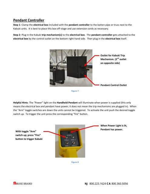
Pendant ControllerStep 1: Clamp the electrical box included with the pendant controller to the batten pipe or truss next to the<strong>Kabuki</strong> units. It is best to place this box off-stage and use extension cords as necessary.Step 2: Plug in the <strong>Kabuki</strong> trip mechanism(s) to the electrical box. The pendant controller gets attached to theelectrical box by the control outlet on the bottom right-hand side. Then plug in the electrical box itself.Outlet for <strong>Kabuki</strong> TripMechanism. (2 nd outleton opposite side)Figure 7Pendant Control OutletHelpful Hints: The “Power” light on the Handheld Pendant will illuminate when power is supplied (this onlymeans the electrical box and pendant have power; it does not mean the trip mechanisms are plugged in). Whenthe “Arm” toggle switches are down the units cannot be triggered. To activate the unit push the desired toggleswitch up. To trigger the unit press the corresponding “fire” button.With toggle “Arm”switch up; press “Fire”button to trigger <strong>Kabuki</strong>When Power Light is lit,Pendant has power.Figure 8ROSE BRAND NJ 800.223.1624 CA 800.360.5056