LASER RANGE FINDER MODULE LRF MOD 3/3CI - Newcon Optik
LASER RANGE FINDER MODULE LRF MOD 3/3CI - Newcon Optik
LASER RANGE FINDER MODULE LRF MOD 3/3CI - Newcon Optik
- No tags were found...

You also want an ePaper? Increase the reach of your titles
YUMPU automatically turns print PDFs into web optimized ePapers that Google loves.
Operation Manual<strong>LASER</strong> <strong>RANGE</strong> <strong>FINDER</strong> <strong><strong>MOD</strong>ULE</strong><strong>LRF</strong> <strong>MOD</strong> 3/<strong>3CI</strong>105 Sparks Ave., Toronto, ON, M2H 2S5, Canada
This page intentionally left blankii
IMPORTANT INFORMATIONRead prior to activationYou have just purchased a sophisticated electro-optical devicethat emits invisible laser radiation. To operate it properly, pleaseread this manual carefully. NEVER direct laser beam at the eyes of people or animals NEVER aim the unit at the Sun or bright sources of light NEVER subject the unit to impacts NEVER transport the unit without its case NEVER disassemble the unit. This may be hazardous for youdue to high voltage currents in the system ALWAYS keep the unit out of children’s reach ALWAYS store the unit in a dry place Caution - use of controls or adjustments, or performance ofprocedures other than those specified herein may result inhazardous radiation exposure Caution - use of optical instruments such as binoculars,mirrors, lenses, etc. with this product will increase eye hazard. Note: Avoid eye exposure to direct laser beam or its closereflection Never aim the unit at highly reflective objects like mirrors andretroreflective surfaces, which are in close proximity to thelaser rangefinder. This can lead to the permanent damage of thephotoreceiver incorporated into the device.iii
CONTENTS1. BRIEF DESCRIPTION ............................................. 3Principle of work ............................................................. 4Key Features .................................................................... 42. DEVICE APPEARANCE .......................................... 53. DELIVERY SET ........................................................ 7Standard delivery set ........................................................ 74. SPECIFICATIONS .................................................... 85. OPERATION INSTRUCTIONS ............................. 10Maximum distance......................................................... 10Module controls ............................................................. 11Measurement procedure ................................................. 11Target selection logic ..................................................... 12Individual Measurement and Scanning regimes ............ 13Operation and service modes ......................................... 13Compass calibration....................................................... 15Correction of the vertical angle (Elevation correction) .. 16Hard calibration ............................................................. 16Soft calibration .............................................................. 18Distance accuracy correction ......................................... 18Gating mode .................................................................. 19Data Recall mode ........................................................... 207. INTERCONNECTIVITY ........................................ 251
8. STORAGE AND MAINTENANCE........................ 389. TROUBLESHOOTING ........................................... 3910. WARRANTY ........................................................... 4011. CUSTOMER SUPPORT ......................................... 4112. QUALITY CERTIFICATE...................................... 442
CAREFULLY READ ALL THE INSTRUCTIONSBEFORE USING!FAILURE TO OBEY THE INSTRUCTIONS WILLVOID THE WARRANTY AND MAY CAUSEINJURY!1. BRIEF DESCRIPTIONThe <strong>LRF</strong> Module uses the same electronics and optics asrangefinder monoculars. These modules can add various rangefinding capabilities into host systems: distance & speedmeasurement, azimuth and elevation measurement.The modules have a built-in computer interface, which enablesimmediate data acquisition by any system with standard serialinterface. Depending on exact model, customer has a choice ofvarious incorporated features, including, but not limited to gatingcapability, fast scan mode, speed measurement, target selectionand more.Typically a rangefinder module becomes a part of:- Thermal imagers- Day/night surveillance systems- Airborne optical systems.Both modules can be integrated into a bigger observation system.The Modules comply with CFR 21, Part 1040.103
Principle of workThe Module sends invisible, eye safe laser pulses to the target.Pulses reflected from the target are captured and processed by thedigital circuitry. The time-of-flight delay between the sent andreceived pulses allows calculating the distance to the target.A built-in digital compass/inclinometer of <strong>MOD</strong> <strong>3CI</strong> measurestarget’s azimuth and elevation simultaneously with ranging.Key Features• Selection of the first, last or the most reflective target• Distance is displayed in meters or yards, speed is displayedin km/h or MPH• Original digital circuitry allows ranging through most typesof glass, bushes and other obstacles• Built-in digital accurate compass/inclinometer, angles aredisplayed in degrees or mils. (<strong>3CI</strong> model only)• On-board memory keeps results of the last 10 measurements,that can be recalled• RS232, bidirectional UART communication4
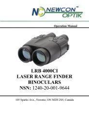
2. DEVICE APPEARANCE4312Fig. 1. Module general view1 - Receiver lens 2 - Laser emitter lens3 - M (Mode) button 4 - A (Action) buttonIdentification and certification label (at the left side)5
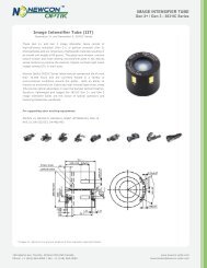
65817243Fig. 3 External Display for Testing & Debugging (optional item)1 – Low battery indicator 2 – Reticle (either -¦- or )3 – Units of measurement 4 – Measurement result5 – Gating indicator 6 – Laser active indicator7 – Ready mode indicator 8 – Setup mode indicator6
5. OPERATION INSTRUCTIONSMaximum distanceThough maximum measurement distance depends on targetreflectivity, weather conditions and other conditions, for mosttargets the unit will provide accurate ranging for up to 2,000meters. Under good conditions a large size target can bemeasured up to 3,000 meters.Target reflectivity depends on its color, surface finish, size,shape, position in relation to the laser beam, etc. Bright targetcolors are more reflective than dark ones. A polished surface ismore reflective than a rough one. Larger targets reflect betterthan small ones. Ranging a target perpendicular to the laser beamprovides better results than the one positioned under a sharpangle to the beam.Weather conditions that influence air transparency (rain, fog,snow, mist) reduce maximum range. Bright sunny days willreduce performance as well, as IR sun radiation may coverreflected laser pulses.While the unit will measure through many glass types, measuringthrough glass may reduce accuracy and range.10
Module controlsModules can be fully controlled via RS-232 connector and/orwith the buttons on the module.The correspondence between the pressing of the buttons and thesignals sent via RS-232 is described in Interconnectivity (Chapter7).In other chapters, this manual describes measurement proceduresand setting measurement parameters assuming operation bypressing of the control buttons.Measurement procedureWhen the Module is off the LCD is blank. To activate it pressand hold for one second the Action (A) button. At start themodule comes into the Ready to Measure mode indicated by theword ‘READY’ on the display.Pressing the Action button in the Ready to Measure modeinitiates measurement. The result of the measurement isdisplayed in a form that depends on the measurement parameters(see Setup Mode).11
Note:• If the target is located below the unit the result of verticalmeasurement (elevation or height) will be preceded withminus (“-“) sign.• If object is going moving away, the speed measurementsresults will be preceded with minus (“-“) sign.Target selection logicOn its way towards the target the laser beam may be reflectedfrom various objects, thus decreasing ranging accuracy. Thesmaller, the farther, and the less reflective is the target – thehigher is the possibility of obtaining an incorrect measurement.To improve accuracy the unit has a built-in target selection logicthat allows user the option of choosing which target to range: thenearest (‘first’), the farthest (‘last’), or the most reflective(‘auto’).This mechanism helps selecting the target when ranging frombehind the bushes, wires, through the falling snow, or in similarconditions. Furthermore, it enables ranging a target in front of abigger object, such as a wire in front of the wall.Note: Even with target selection logic the unit may not always beable to range the desired target as its reflectivity may be too lowto produce enough laser beam reflections for statistically reliablecalculation. Individual Measurement and Scanning regimes12
Individual Measurement and Scanning regimesThe unit can operate in two methods: (1) IndividualMeasurement and (2) scanning. In Individual Measurementmethod the unit performs single measurement when Actionbutton is pressed shortly, in Scanning regime the unit repeatedlymeasures and displays results every second while A button ispressed.To activate Scanning regime press and hold Action button inReady mode. The unit will work in Scanning regime whileAction button is pressed.Scanning or Individual Measurement regimes are available forany selected mode of measurement. When two or moreparameters are measured in Scanning regime though first resultwill be displayed, the second and other results will be shown atthe display if Action button is released. Nevertheless all data istransferred to the PC and recorded in internal memory, and maybe recalled (see Data Recall mode for details.).During control of the device via computer interface, frequency ofindividual measurements will be defined by the host system.Operation and service modesPressing Mode button (5, Fig.1) in Ready mode switches the unitbetween modes of operation, to activate any desired mode fromthe menu you must confirm your selection by pressing Actionbutton (6, Fig.1)The unit has the following modes of operation:13
• Ready – Unit is ready to perform measurements,• dFLt – sets default mode of operation with factory settings,• GAtE – allows to set gating distance for measurement,• Std – allows the user to select single action measurements:o Distance only (d)o Compass Only (C) 1o Elevation Only (E) 1o Speed Only (S)o Height Only (H) 1o Speed + Distance (Sd)o Distance +Compass + Elevation (dCE) 1• Unit – allows the user to select units of desiredmeasurements,o Distance from M to Yo Compass & Elevation from Mils to Degreeso Speed from KMH to MPH** note this option is only available if Std Speed isselected• rEc – allows data recall of the last 10 measurement results,o CLr – Clears all Measurement• SEt – allows the user to select the following advancedoptions:o FrSt – First Target Measurement14
o LASt – Last Target Measuremento PLGr – Communication to PLGR 1 GPS*o PC – Communication to PC*o Reticule – Change reticule from + (cross) to(rectangle)o CAL – Calibration menu▪ CALc – compass calibration (CImodel only)▪ Corr – accuracy correction of activemeasurement parameters* not shown in the menu if currently selected1 – available for CI model only.Compass calibrationFull calibration process consists of three procedures, which shallbe conducted in the following sequence:1. Elevation correction2. Hard calibration3. Soft CalibrationHowever all three procedures shall be done only at initialinstallation and integration of the device, or if some largehardware elements permanently attached to the device werechanged. For example bracket made of magnetic metal wasreplaced or modified. If calibration is performed only to improveaccuracy of readings, only the Elevation correction and Softcalibration shall be performed.15
Correction of the vertical angle (Elevation correction)- Turn on the <strong>LRF</strong>.- In the <strong>LRF</strong> menu, select «Std», then «E». Press ACTION.- Select «SET», then «CAL». Press ACTION.- Position <strong>LRF</strong> strictly flat. Select «corr» and press ACTION.If device is not positioned perfectly level during calibration, thisprocess will introduce permanent error for all futuremeasurements.Upon finishing correction process, perform one elevationmeasurement. If device shows measurement result more thanzero degrees, it means correction was not performed. Pleaserepeat all steps of the correction process again.Hard calibrationGeneral notes for the process:- Axis of rotation for this process shall pass through the center ofred PCB board (compass) installed onto the <strong>LRF</strong> module.- During all calibration procedures, always put as far as possibleall magnetic/metal parts and devices that generateelectromagnetic interference (example – Cellphone) from themeasurement area, unless these parts or devices will bepermanently used in conjunction with the <strong>LRF</strong> device.16
Procedure:- Turn on the <strong>LRF</strong>.- In the <strong>LRF</strong> menu select «SET», then «CAL». Press ACTION.- When the text «CALc» is shown, set the <strong>LRF</strong> horizontally on aflat surface, where the <strong>LRF</strong> will be rotated around vertical axis.Note: to achieve as accurate calibration results as possible, thedigital compass should be exactly on the axis of horizontalrotation.- Press the ACTION. - -- Start rotating the <strong>LRF</strong> module toperform one or two full rotations duration 1 min. The display willbe blinking «CAL» during entire process.- When the display switches to «CALc», change <strong>LRF</strong> position tobe on the left side down. Note: to achieve as accurate calibrationresults as possible, the digital compass (red PCB) should beexactly on the axis of rotation location of the axis of rotation forthis procedure.- Press ACTION.- Start rotating the <strong>LRF</strong> module to perform on or two fullrotations duration 1 min. The display will be blinking «CAL».When display switches to «CALS», it means that calibration isfinished.- Press <strong>MOD</strong>E button to exit the calibration mode.17
Soft calibrationPrior to conducting the procedure determine accurate direction toNorth, West, South and East, accuracy of these references willdefine accuracy of the compass calibration.- Turn on the <strong>LRF</strong>.- In the <strong>LRF</strong> menu select «SET», then «CAL». Press ACTION.- Then select «CALS» and press ACTION- When the display shows «C 0 °», the <strong>LRF</strong> shall be sethorizontally and aim the <strong>LRF</strong> to the North (0 degrees), pressACTION.- When the display shows «C 90 °», the <strong>LRF</strong> shall be sethorizontally and aim the <strong>LRF</strong> to the East (90 degrees), pressACTION.- When the display shows «C 180 °», the <strong>LRF</strong> shall be sethorizontally and aim the <strong>LRF</strong> to the South (180 degrees), pressACTION.- When the display shows «C 270 °», the <strong>LRF</strong> shall be sethorizontally and aim the <strong>LRF</strong> to the West (270 degrees), pressACTION.- When the display shows «corr» press <strong>MOD</strong>E to exit thecalibration mode.Distance accuracy correctionIf the System produces any measurement errors that lie beyondunit specification, it may be an indication that unit requirescalibration similar to one conducted at production level. To doaccuracy correction:18
Turn on the <strong>LRF</strong>In the <strong>LRF</strong> menu enter submenu “Std” and then select “d”. bypressing Action.Enter submenu “Set” and select “Cal”.Install unit at 1 meter distance from any large flat target.Select “corr” in the menu by pressing Action.1 – Accuracy of distance correction will depend on accuracy ofinstallation against target. If distance is 0.9 meters, then unit willhave 0.1 m offset during all future measurements.2 – Target should not have high-reflective surface (white color isnot considered high reflective in this case).3 – If device detects measurement result more than 0.0 o, elevationcorrection was not performed.Gating modeIn this mode gating function is activated: here user can set theminimal distance to the target, any object closer than the gatingdistance will be ignored.To select Gating Mode:• Select GAtE from main menuMinimal gating distance of 0 meters (display: 000 m) will beinitially set, further pressing M button will increase gatingdistance by 100 m up to 2,900 m. When the desired distance isreached – select it by pressing Action button.OVER 100M – indicates that gating is active19
To deactivate gating choose gating value zero.Note: The gating distance can only be increased. To exit thegating selection cycle without setting any gating distance clickthrough full gating range with M button or hold M button for 2seconds.Gating feature helps measuring remote targets in unfavourableatmospheric and environmental conditions by eliminatingreflections from snowflakes, raindrops, industrial wires, treebranches, etc. At the same time, if gating distance is setincorrectly, you can remove the desirable object frommeasurement range.Data Recall modeIn Data Recall mode results of the last 10 measurements can bedisplayed.Measurement results are saved in on-board memory in setsdepending on the parameters set for measuring, for instance, ifonly distance is measured - the set will consist of one number, ifdistance and azimuth are measured – the set will consist of twonumbers.To enter Data Recall mode select rEc from mode menu.First measurement set number (display name: rEc 1) will startflashing.Pressing M button moves the unit along the list of measurementset numbers and measurement results:20
Ec 1, distance 1, azimuth 1, elevation 1,rEc 2, distance 2, azimuth 2, elevation 1, …,rEc 0, distance 0, azimuth 0, elevation 0.Measurement sets are numbered in reverse order: first recalledset is the result of the last measurement. If any parameter has notbeen measured it will not be shown in the recall package.Pressing A button at any moment within the list of recalledresults brings the unit to Ready to Measure mode.Choosing cLr at the end of recalled data will erase the devicememory.Additional display informationAdditional indication is displayed in the Ready to Measuremode:Y or MKMH orMPHIndicates that distance is measured anddisplayed in yards or metersIndicates that speed is measured and displayedin km/h or mph° Indicates that only azimuth is measured° Indicates height in meters or azimuth is milsmeasured21
GPS interconnectivity (CI model only)The <strong>LRF</strong> can transmit the acquired data to a GPS receiver usingDB15 connector of the special GPS cable (optional). Note: thecommunication protocol using this communication change toproprietary PLGR/DAGR protocol and unit will stop respondingto standard PC commands.To establish communication with GPS receiver, perform thefollowing steps:• Choose dFLt measuring mode;• Switch the rangefinder to PLGr mode;• Connect the rangefinder and GPS unit with the cable.For each measurement GPS will display the absolute coordinatesof your target.Note: If the rangefinder is not set initially to dFLt mode, theGPS may not operate properly.Note: do not forget to return <strong>LRF</strong> device back to PCcommunication if you are planning to use protocol as describedin the Paragraph 7.22
6. BEST MEASURING TECHNIQUELaser range finder module measures distance by catching a laserbeam reflected from the target. Everything that improvesreflection increases the measurement reliability and maximumrange.1. Aim at a surface on the target that is closest to theperpendicular to the laser beam. The closer you get – thestronger will be the reflection.2. The unit deploys sophisticated software that tries tounderstand which target you are aiming at. However, due tobeam divergence several objects may produce a strongreflection. To help the system recognise the target the TargetSelection Logic may be used.For example, if ranging a wire in front of a building,selecting the “first” target will produce a more reliableresult. Alternatively, when aiming at a chimney behind thetrees, selecting “last” target will be better. By default theSystem assumes “auto” target selection, that is, the objectproducing the most reflections will be considered a target.23
3. Another way to improve reliability of measurement is to usethe gating mechanism. When gating is active reflectionsfrom all objects closer than the gating distance will beignored. This is especially effective when ranging inunfavourable atmospheric conditions, that is, in the rain, fog,haze or bright sun. Gating provides better results than the“last” target selection, but it requires preliminary roughdistance estimation to cut off all objects closer than thechosen one.Note: the Gating setting is remembered by the System untilaltered. Therefore, if you forget to turn the gating off, the nexttime you start measuring it can ignore the desired object, if it iscloser than the gating distance. The unit will display four dashesinstead of the measurement results. “Over 100 meters” displayindicator shows active gating.24
7. INTERCONNECTIVITYThe unit supports RS-232 interface. Physical connection isperformed with threaded coupling mechanism designed forheavy-duty outdoor applications.Note: Do not apply excessive force when disconnecting RS-232cable. Damage to cable or connector resulting from impropertreatment is not covered by warranty.The communication port must be initiated prior to connecting theunit to the computer. The data is transmitted as hex string codewith fixed baud rate of 38400 bit/sec.Note: the device connector could be different from the onedescribed in the manual as it can be customized per customerrequirements.Note: if PLGR communication is selected from the device menu,the described in this paragraph protocol is going to be disabled,please select “PC” communication protocol in the menu again.7.1 InterfaceThis physical interface uses two lines to an external UART(Universal Asynchronous Receiver/Transmitter) port. The signalrepresents the serial asynchronous communications protocol,known as RS-232. A typical UART frame is shown in Figure 1.25
It comprises a Start bit, 8 data bits, and a Stop bit, no parity bit.The baud rate is 38400 bits/s.UART FrameSTARTB0B1B2B3B4B5B6B7STOPSTARTB0B1B2Figure 1. Data Frame7.2 <strong>LRF</strong> Configuration (<strong>MOD</strong>E register)<strong>MOD</strong>E register consists of 11 bit, its contents is user editable andpresents all major <strong>LRF</strong> features and settings. Below is shownformat of the <strong>MOD</strong>E register and purpose of each bit:B10 B9 B8 B7 B6 B5 B4 B3 B2 B1 B0B0 units of distance measurement, 0 – meters, 1 – yards;B1 reserved bit for units of distance measurement, foot. NOTUSED in this versionB2 units of compass measurement, 0 – mils, 1 – degrees;B3 units of speed measurement, 0 – KM/H, 1 – MP/H;B5, B4 target selection, 00 –auto target, 01 – first target, 10 – lasttarget;B6 communication type, 0 – PC communication, 1 – GPScommunication;B7 reticle type, 0 – rectangular, 1- cross;B10-B8 settings for type of the measurement:26
B10 B9B8{binary}Measurements 1 ,Comments000 dCE Distance+Azimuth+Elevation001 d Distance010 C Azimuth011 E Elevation100 S Speed101 H Height110 Sd Speed+distance 2OthersNot usedNotes:1. The same mnemonics as displayed on the indicator.2. Speed measurement requires prolonged time interval,distance at the end of measurement interval will be displayed.27
7.3 List of communication commandsCommunication commands table.Command syntaxCommand name<strong>LRF</strong> response(PC =><strong>LRF</strong>)OpenCOMportinthe PC 1OpenCOMport(<strong>LRF</strong> => PC),ASCII$RDY No responseNotes<strong>LRF</strong> should reply within20ms with ready statusUnit does not provide anyresponse if it is alreadyON.#SStatusrequest$RDY Command to initializecommunication. Internal<strong>LRF</strong> watchdog timer willbe disable (auto shut-offfunction is disabled)#D Default#EChangesettings$RDY$RDY Resetting gating value and<strong>MOD</strong>E register to defaultstateSet new values for gatingand <strong>MOD</strong>E register28
#AMeasurement#R Recall#M#CClearmemoryStartcalibration$RNO**$RDY$RDY $RDY Not able to measure (errorduring measurement)Measured resultRecalled result, every“Recall” command willpull one measurementresult from unit’s memorystarting from the mostIf there are no saved resultsin the device memory orthe oldest result wasalready transferred to thePC 5Erase all saved results inthe device memoryInitialize compasscalibration process. Theprocess will be finishedautomatically in 1 minute.29
#FCloseCOMportatthe PC1TerminatecommunicationCloseCOMport30Command ofcommunicationtermination. Internal <strong>LRF</strong>watchdog timer will beenabled auto shut-offfunction enabled). Thiscommand should befollowed by COM portclosing.This action should follow“Terminatecommunication” commandwith delay less than 5seconds. If it was notperformed, unit will go offwithin 5 seconds and thenwill be ON again.Notes:1. Close and open port command syntaxes cannot be shown hereas it depends on communication program/environment used for<strong>LRF</strong> interfacing.2. Status description is provided in subparagraph 7.5.3. stands for low battery indicator. It replaces thereserved bit B15 in the result eighth byte DB8 (see paragraph 6).Value 1of this bit means that battery has to be replaced, zeromeans that battery is not discharged.4. Result description is provided in subparagraph 7.6.5. The maximum quantity of recall results is 10.
Symbols $RDY, $RNO, * are ASCII strings. stands for theHEX 0A, stands for HEX 0D.7.4 <strong>LRF</strong> default state (factory settings)Gating value, Gate = 0 meters<strong>MOD</strong>E register (all zeros): units for distance measurements aremeters, azimuth and elevation in mils, target selection – auto,communication type – PC, reticle – rectangular.7.5 <strong>LRF</strong> status<strong>LRF</strong> status represents all current device settings together withbattery status represented by concatenation of 3 bytes = BYTE1 BYTE2 BYTE3 = 0 (all bytes values are equal to zero).< NEW STATUS> is a set of <strong>LRF</strong> modes to be transferred to<strong>LRF</strong> from PC side. By changing the STATUS words <strong>LRF</strong>operator is able to change the following parameters:1. Gating value in meters.2. Units of measurements.3. Target selection logic.4. Communication type.5. Type of the reticle.6. Parameters to measure.31
BYTE 1 (default value)B7 B6 B5 B4 B3 B2 B1 B00 0 0 0 0 0 0 0B7reserved bit{B6-B0} represents gating value (from 0 to 39) as{binary}. Gating value 0 means that no gatingis set. Gating value 39 means that gating valueis set as 3900 meters.BYTE 2 BYTE 3 (default values)B15 B14 B13 B12 B11 B10 B9 B8 B7 B6 B5 B4 B3 B2 B1 B00 0 0 0 0 0 0 0 0 0 0 0 0 0 0 0{B10-B0} represents <strong>MOD</strong>E register (see paragraph 2).B11 represents low battery flag. Low battery flag 1means that battery has to be replaced.{B15-B12} reserved bits7.6 Format of measurement resultsThe data string that is transferred to the computer as results hasthe following structure: consists of 8 bytes = DB1 DB2 DB3 DB4 DB5 DB6 DB7 DB832
{DB2 DB1} result of measurement for first chosenparameter {binary}{DB4 DB3} result of measurement for second chosenparameter {binary}{DB6 DB5} result of measurement for third chosenparameter {binary}{DB8 DB7} result units of measurement for all three chosenparameters {binary}Result of measurement can be calculated as value of data bitewith high index number multiplied by 256 plus value of data bitewith low index number.Example: Result for the first chosen parameter when DB2 is{00000011} and DB1 is {10000001}Result = DB2 x 256 + DB1=3 x 256 + 129=768 + 129 = 8B15 B14 B13 B12 B11 B10 B9 B8 B7 B6 B5 B4 B3 B2 B1 B00 0 0 0 0 0 0 0 0 0 0 0 0 0 0 0{B0-B3} unit of measurement for first chosen parameter(zero if no result){B4-B7} unit of measurement for second chosenparameter (zero if only one parameter waschosen){B8-B11} unit of measurement for third chosen parameter(zero if only one or two parameters werechosen){B12-B15} reserved bits33
Description of the result is presented in the table below:B3/B7/B11B2/B6/B10B1/B5/B9B0/B4/B8Result typeComments0 0 0 0 NoneNo result, the same as “----“on the unit display0 0 1 0 S, km/h Speed in Km/H0 0 1 1 S, mp/h Speed in Mp/H0 1 0 0 D, m Distance in meters0 1 0 1 D, y Distance in yards1 0 0 0 H, m Height in meters1 0 0 1 H, y Height in yards1 1 0 0 C, mil Azimuth in mils1 1 0 1 C, deg Azimuth in degrees1 1 1 0 E, mil Elevation in mils1 1 1 1 E, deg Elevation in degreesOther combinationsNot used34
7.7 Output connector pin layout and cable diagramThe unit supports RS-232 interface. The data is transmittedas hex string code with fixed baud rate of 38400 bit/sec, 8bits, one stop bit, and no parity.Physical connection is performed through circular connectordesigned for the heavy-duty outdoor applications, theconnector is located on the bottom of the device. Currently<strong>Newcon</strong> supplies two types of connectors, one with quickrelease connector or screw-locking connector. Operationwith both types is described in the manual.Do not apply excessive force when disconnecting cable.Damage to cable or connector resulting from improperhandling is not covered by warranty.To attach the cable to the rangefinder match the key on theplug (1, Fig. 4A, or 1, Fig. 4B) with the corresponding keyon the socket and then push gently the plug holding it by itscasing (3, Fig. 4A or 3, Fig. 4B ), in case of the cable shownon Fig. 4B you should hear a click meaning that connectorplug and receptacle are latched. In case of the cable shownon Fig. 4A, start rotating the sleeve until the plug is lockedin the receptacle, do not overtighten the sleeve as it maydamage the thread.35
32 1Fig. 4A. Computer cableconnector1 – Key; 2 – Sleeve; 3 -Rubber casing321Fig. 4B. Computer cableconnector1 – Key; 2 – Sleeve; 3 -Rubber casingTo detach the cable slide sleeve (2, Fig. 4B) away from theunit and pull the plug out or unscrew the sleeve (2, Fig. 4A)and detach the plug.36
<strong>LRF</strong> <strong>MOD</strong> 3/<strong>3CI</strong>ReceptacleNCGNDNCNDDTETxDRxD1234567Fig. 5. Communication Port DiagramPin1 - (NC)Pin2 - (GND)Pin3 - (NC)Pin4 - (NC)Pin5 - (DTE)Pin6 - (TxD)Pin7 - (RxD)Not connectedSignal groundNot connectedNot connectedDevice enable signal, high level logic signal requiredfor turning on the module. In case if module isconnected to COM port, this signal line is toggled tohigh level automatically every time when the COMport is openedTransmitting channel for the Module, RS232 levelReceiving channel for the Module, RS232 level37
8. STORAGE AND MAINTENANCEThe unit is a sophisticated precision optical instrument equippedwith laser and electronics. Therefore, it should be handled withdue care.Keep away from direct sunlight.Avoid impacts, jolts, dust, moisture, and sharp changes oftemperature.Do not use the device at temperatures higher than 50 o C(122 o F).Do not touch optical surfaces by hands. Doing so maydamage the anti-reflection coating.Clean optical surfaces only with professional camera lenscleaning supplies.Clean the exterior of the unit with a soft clean cloth.Keep away from heating appliances and central heating.All repair works must be performed by an authorizedservice.38
9. TROUBLESHOOTINGRanging does not work. Check the power supply voltage. Check presence of turn on signal. Check that communication with the unit is properlyestablished by sending status request command andreceiving proper response. Ensure that proper operating mode is selected. Make sure that neither your hand nor finger is blockinglaser emitting lens or receiver lens. Check that the target is within measuring range of thedevice and the gating mode does not cut it off.39
10. WARRANTY<strong>Newcon</strong> <strong>Optik</strong> warrants this product against defects in materialsand workmanship for one year from the date of the originalpurchase. Longer warranty is available, subject to the terms ofthe specific sales contract. Should your <strong>Newcon</strong> <strong>Optik</strong> productprove to be defective during this period, please deliver theproduct securely packaged in its original container or anequivalent, along with the proof of the original purchase date, toyour <strong>Newcon</strong> <strong>Optik</strong> dealer.<strong>Newcon</strong> <strong>Optik</strong> will repair (or, at its option, replace with the sameor comparable model), the product or part thereof, which, oninspection by <strong>Newcon</strong>, is found to be defective in materials orworkmanship.What This Warranty Does Not Cover:<strong>Newcon</strong> <strong>Optik</strong> is not responsible for warranty service should theproduct fail as a result of improper maintenance, misuse, abuse,improper installation, neglect, damage caused by disasters suchas fire, flooding, lightning, improper power supply, or serviceother than by personnel authorized by <strong>Newcon</strong> <strong>Optik</strong>.Postage, insurance and shipping costs incurred while presentingyour <strong>Newcon</strong> <strong>Optik</strong> product for warranty service are yourresponsibility.If shipping from North America please include a cheque ormoney order payable to <strong>Newcon</strong> <strong>Optik</strong> for the amount of USD$15 to cover handling and return shipping.40
11. CUSTOMER SUPPORTShould you experience any difficulties with your <strong>Newcon</strong> <strong>Optik</strong>product, consult this manual first.If the problem remains, contact our customer support departmentat +1 (416) 663-6963 or toll free at 1-877-368-6666 (NorthAmerica only). Our operating hours are 0900h to 1700h EasternStandard Time, Monday through Friday.Under no circumstances should equipment be sent to <strong>Newcon</strong><strong>Optik</strong> without authorisation from our technical supportdepartment.<strong>Newcon</strong> <strong>Optik</strong> accepts no responsibility for unauthorized returns.To locate a <strong>Newcon</strong> <strong>Optik</strong> Authorized Dealer:Call: +1(416) 663-6963 Fax: +1(416) 663-9065Email: newconsales@newcon-optik.comVisit: www.newcon-optik.com41
This page intentionally left blank42
This page intentionally left blank43
12. QUALITY CERTIFICATE<strong>MOD</strong> 3<strong>MOD</strong> <strong>3CI</strong>The unit has passed the quality inspection.Production dateSerial numberQuality InspectorPurchase date44
R1.T – 10.13NEWCON OPTIKPrinted in Canada