Pub 30 Copper-Nickel Alloys, Properties and Applications
Pub 30 Copper-Nickel Alloys, Properties and Applications
Pub 30 Copper-Nickel Alloys, Properties and Applications

You also want an ePaper? Increase the reach of your titles
YUMPU automatically turns print PDFs into web optimized ePapers that Google loves.
<strong>Copper</strong> Development Association<strong>Copper</strong>-<strong>Nickel</strong> <strong>Alloys</strong>, <strong>Properties</strong> <strong>and</strong> <strong>Applications</strong>TN<strong>30</strong>, 1982
<strong>Copper</strong>-<strong>Nickel</strong> <strong>Alloys</strong>, <strong>Properties</strong> <strong>and</strong> <strong>Applications</strong>TN<strong>30</strong>September 1982Members as at September 1982Amalgamated Metal Corp LtdAmetalco LtdAnglo American Corporation of South AfricaASARCO IncN C Ashton LtdBICC Cables Ltd – Metals GroupBilliton International Metals BVBoliden AktiebolagBougainville <strong>Copper</strong> LtdBr<strong>and</strong>eis Intsel LtdBritish American Metals Co LtdThe British Non-Ferrous Metals FederationCharter Consolidated LtdChile <strong>Copper</strong> LtdCIPECElkington <strong>Copper</strong> Refiners LtdFalconbridge <strong>Nickel</strong> Mines LtdHudson Bay Mining & Smelting Company LtdIMI LtdINCO Europe LtdJohnson Matthey Metals LtdJohnson & Nephew (Non-Ferrous) LtdKidd Creek Mines LtdLornex Mining Corporation LtdMcKechnie Brothers plcMessina LtdMetal Sales Company LtdMitsubishi CorporationMount Isa International Pty LtdNor<strong>and</strong>a Sales Corporation LtdRatcliffs (Great Bridge LtdRio Tinto Minera S ARTZ London LtdSogemin LtdSouthern Peru <strong>Copper</strong> CorporationSumitomo CorporationThe Wednesbury Tube CompanyAcknowledgementsThe <strong>Copper</strong> Development Association is grateful to all who have supplied assistance, information,comment <strong>and</strong> illustrations <strong>and</strong> especially to: the BNF Metals Technology Centre <strong>and</strong> the Ministry ofDefence (Navy).Extracts from the relevant British St<strong>and</strong>ards are published by permission of the British St<strong>and</strong>ardsInstitution, 2 Park Street, London W1A 2BS. Complete st<strong>and</strong>ards with all the relevant information may bepurchased from BSI Sales.<strong>Copper</strong> Development Association<strong>Copper</strong> Development Association is a non-trading organisation sponsored by the copper producers<strong>and</strong> fabricators to encourage the use of copper <strong>and</strong> copper alloys <strong>and</strong> to promote their correct <strong>and</strong>efficient application. Its services, which include the provision of technical advice <strong>and</strong> information,are available to those interested in the utilisation of copper in all its aspects. The Association alsoprovides a link between research <strong>and</strong> user industries <strong>and</strong> maintains close contact with other copperdevelopment associations throughout the world.Website:Email:www.cda.org.ukhelpline@copperdev.co.ukCopyright:All information in this document is the copyright of <strong>Copper</strong> Development AssociationDisclaimer: Whilst this document has been prepared with care, <strong>Copper</strong> Development Association cangive no warranty regarding the contents <strong>and</strong> shall not be liable for any direct, indirect or consequentialloss arising out of its use
ContentsContents........................................................................................................................................................1Tables ..............................................................................................................................................2Figures ..............................................................................................................................................2Introduction .................................................................................................................................................3Specifications, <strong>Properties</strong> <strong>and</strong> Availability................................................................................................3Impurities ..............................................................................................................................................4Resistance to Corrosion <strong>and</strong> Bio-Fouling ..................................................................................................6Fabrication.................................................................................................................................................10Machining...................................................................................................................................................10Joining ........................................................................................................................................................10<strong>Copper</strong>-<strong>Nickel</strong> Clad Steel..........................................................................................................................13Pipelines for H<strong>and</strong>ling Sea-Water............................................................................................................14Condensers & Heat Exchangers...............................................................................................................16Desalination Plant......................................................................................................................................18Multi-Stage Flash Distillation Plants ...........................................................................................................18Principles of Flash Distillation ....................................................................................................................18Materials for Flash Distillation Plants .........................................................................................................18Sea Water Intakes......................................................................................................................................20Boat <strong>and</strong> Ship Hulls...................................................................................................................................21Offshore Structures ...................................................................................................................................24Fish Farming..............................................................................................................................................25Hydraulic Brake Tubing for Vehicles......................................................................................................26Hydraulic <strong>and</strong> Instrumentation Tubing for Marine <strong>and</strong> Offshore Use ...............................................27Gas Pipelines ..............................................................................................................................................27Selected Bibliography................................................................................................................................31General Compositions & <strong>Properties</strong> ............................................................................................................31Corrosion <strong>and</strong> Marine Biofouling................................................................................................................31Welding ............................................................................................................................................32Cladding steel with copper nickel................................................................................................................32Heat Exchangers..........................................................................................................................................33Desalination Plants ......................................................................................................................................33Sea Water Pipelines.....................................................................................................................................34Condensers ............................................................................................................................................34Sea Water Intakes ........................................................................................................................................35Boat <strong>and</strong> Ship Hulls.....................................................................................................................................35Offshore <strong>Applications</strong>..................................................................................................................................36Fish Farming ............................................................................................................................................36Hydraulic Pipelines......................................................................................................................................361
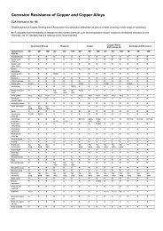
TablesTable 1 – Application St<strong>and</strong>ards for various Wrought <strong>and</strong> Cast Products 5Table 2 – Availability of Wrought <strong>Copper</strong>-<strong>Nickel</strong> <strong>Alloys</strong> 5Table 3 – 90-10 copper-nickel-iron alloy. Mechanical properties 5Table 4 – 70-<strong>30</strong> copper-nickel-iron alloy. Mechanical properties 6Table 5 – Comparison or corrosion behaviour of CuNi10Fe <strong>and</strong> CuNi<strong>30</strong>Fe in seawater 7Table 6 – Fouling resistance of various alloys in quiet seawater 8Table 7 – Tolerance for pitting under fouling <strong>and</strong> crevice corrosion in seawater 9Table 8 – Suitability of joining processes for copper-nickel alloys 11Table 9 – Welding products <strong>and</strong> processes for copper-nickel alloys 12Table 10 – Typical composition ranges of weld metals for copper-nickel alloys 12Table 11 – Some applications of copper-nickel alloys for ships’ hulls 23Table 12 – Comparison between various specifications for 90/10 <strong>and</strong> 70/<strong>30</strong> copper-nickel alloys 29FiguresFigure 1 – Corrosion rates of materials in flowing seawater. 8Figure 2 – Cu-Ni-Fe diagram showing hot short areas 13Figure 3 – Roughness factors for copper-nickel alloys <strong>and</strong> steel 15Figure 4 – Section of single deck MSF desalination plant 192
Introduction<strong>Copper</strong>, the most noble of the metals in common use, has excellent resistance to corrosion in theatmosphere <strong>and</strong> in fresh water. In sea-water, the copper nickel alloys have superior resistance tocorrosion coupled with excellent anti-fouling properties.<strong>Copper</strong> cladding of wooden hulled warships, introduced by the Royal Navy in the 18 th centuryto prevent damage by wood-boring insects <strong>and</strong> worms such as the teredo, was discovered toprevent biofouling by weed <strong>and</strong> molluscs. This meant that ships could stay at sea for longperiods without cleaning. Nelson’s successful blockade tactics <strong>and</strong> subsequent victory atTrafalgar was partly due to the superior speed of his clean-hulled ship.The addition of nickel to copper improves its strength <strong>and</strong> durability <strong>and</strong> also the resistance tocorrosion, erosion <strong>and</strong> cavitation in all natural waters including sea-water <strong>and</strong> brackish, treatedor polluted waters. The alloys also show excellent resistance to stress-corrosion cracking <strong>and</strong>corrosion fatigue. The added advantage of resistance to bio-fouling, gives a material ideal forapplication in marine <strong>and</strong> chemical environments for ship <strong>and</strong> boat hulls, desalination plant,heat exchange equipment, sea-water <strong>and</strong> hydraulic pipelines, oil rigs <strong>and</strong> platforms, fish farmingcages, sea-water intake screens, etc.The purpose of this publication is to discuss typical applications for copper-nickel alloys <strong>and</strong> thereasons for their selection. The two main alloys contain either 10 or <strong>30</strong>% nickel, with iron <strong>and</strong>manganese additions as shown in Table 12, which lists typical international <strong>and</strong> nationalst<strong>and</strong>ards to which the materials may be ordered in wrought <strong>and</strong> cast forms.Specifications, <strong>Properties</strong> <strong>and</strong> AvailabilityThe copper-nickel alloys are single phased throughout the full range of compositions <strong>and</strong> manyst<strong>and</strong>ard alloys exist within this range, usually with small additions of other elements for specialpurposes. The two most popular of the copper rich alloys contain 10 or <strong>30</strong>% of nickel. Somemanganese is invariably present in the commercial alloys as a deoxidant <strong>and</strong> desulphurizer; itimproves working characteristics <strong>and</strong> additionally contributes to corrosion resistance in seawater.Other elements which may be present singly or in combination are:Iron, added (up to about 2% ) to the alloys required for marine applications. It confersresistance to impingement attack by flowing sea-water. The initial development of the optimumcompositions of the copper-nickel-iron alloys in the 19<strong>30</strong>’s has been described by G. L. Bailey(see bibliography). This work was to meet naval requirements for improved corrosion-resistantmaterials for tubes, condensers <strong>and</strong> other applications involving contact with sea water.Throughout the publication the term “copper-nickel” refers in fact to copper-nickel-iron alloys.Chromium, can be used to replace some of the iron content <strong>and</strong> at one per cent or moreprovides higher strength. It is used in a newly-developed <strong>30</strong>% nickel casting alloy (IN-768)*. Alow-chromium 16% nickel wrought alloy (C72200) † has been developed in the USA.Niobium, can be used as a hardening element in cast versions of both the 10% <strong>and</strong> <strong>30</strong>% nickelalloys (in place of chromium). It also improves weldability of the cast alloys.Silicon, improves the casting characteristics of the copper-nickel alloys <strong>and</strong> is used inconjunction with either chromium or niobium.* INCO Designation† American Society for Testing & Materials (ASTM) Unified Numbering System designation.3
Tin confers an improved resistance to atmospheric tarnishing <strong>and</strong> at the 2% level is used with9% nickel to produce the alloy C72500 †. This has useful spring properties <strong>and</strong> is used in theelectronics industry. It is not recommended for marine applications.ImpuritiesImpurity elements such as lead, sulphur, carbon, phosphorus, etc. in the amounts to be found incommercial material, have little or no effect on corrosion performance, but because of theirinfluence on hot ductility may impair weldability <strong>and</strong> hot workability <strong>and</strong> are, therefore,carefully controlled.Variations in the common national <strong>and</strong> international specifications for the 90/10 <strong>and</strong> 70/<strong>30</strong>alloys are shown in Table 12. From this the extent to which various st<strong>and</strong>ard materials overlapmay be compared. In some st<strong>and</strong>ards the impurities are more closely controlled than others butin all cases the material supplied will be fit for its designated purpose. However, the limits forsome impurities (such as lead) in the specifications do not guarantee weldability by alltechniques. In cases of doubt the suppliers advice should be obtained.The forms in which the various st<strong>and</strong>ard compositions are available are shown in Table 1,which shows the common international (ISO), British (BS), Ministry of Defence, Navy (DGS),American (ASTM) <strong>and</strong> German (DIN) st<strong>and</strong>ards for wrought <strong>and</strong> cast forms. Future referencesin this publication to 90/10 <strong>and</strong> 70/<strong>30</strong> copper-nickel alloys refer to the alloys normallycontaining iron <strong>and</strong> manganese as used in marine applications. When the 70/<strong>30</strong> alloy ismentioned it should be borne in mind that in some circumstances it is preferable to use the alloywith 2% iron, 2% manganese (BS designation CN 108) rather than the alloy with lower iron <strong>and</strong>manganese (CN 107).For information, Table 2 shows the common production limits on the sizes of these materials.This is a guide only. Material in these sizes will not always be in available stock. It may also bepossible to make material outside these sizes by arrangement.Provided foundry practice is good, satisfactory complex castings can be made in these types ofalloy. The 90/10 composition has a lower melting <strong>and</strong> pouring temperature than the 70/<strong>30</strong> alloy.Normally for small castings, additions of some extra alloying elements are made for improvedproperties. The only official British specification is the Ministry of Defence DGS 229 coveringa complex alloy containing additions of manganese, iron <strong>and</strong> aluminium (Trade name Hiduron501) *. The introduction of electric furnace melting in foundries has led to a greater interest in70/<strong>30</strong> alloys, in particular a chromium containing INCO proprietary alloy (IN 768) which hasexceptional resistance to impingement corrosion, making it ideal for heavy duty pump <strong>and</strong>piping applications. Electric melting practice is desirable for attaining the correct meltingtemperature in reasonable time <strong>and</strong> to give a cleaner furnace atmosphere to avoid contamination<strong>and</strong> gas pick up.For security <strong>and</strong> other reasons the copper-nickel alloys used for a large percentage of theworld’s coinage requirements do not necessarily conform to any of the common specificationsquoted. Generally, they do not include the iron, manganese or other significant additions. Sincethis is a very specialised application, the coinage alloys are not included in this publication.The typical mechanical properties for the 90/10 <strong>and</strong> 70/<strong>30</strong> alloys given in Table 3 <strong>and</strong> Table 4are taken from ‘The <strong>Copper</strong>-<strong>Nickel</strong> <strong>Alloys</strong>— Engineering <strong>Properties</strong> <strong>and</strong> <strong>Applications</strong>’,published by lNCO Europe Ltd. Further data are included in that publication <strong>and</strong> also theappropriate CIDEC Data Sheets (see Bibliography). Material should normally be ordered to theappropriate minimum properties quoted in the ISO or national specification used.* Langley <strong>Alloys</strong> Ltd designation.4
Table 1 – Application St<strong>and</strong>ards for various Wrought <strong>and</strong> Cast Products* Filler Wire for Welding.† To be included at next revision.‡ 70/<strong>30</strong> alloy only.§ 90/10 alloy onlyTable 2 – Availability of Wrought <strong>Copper</strong>-<strong>Nickel</strong> <strong>Alloys</strong>(The sizes below represent typical manufacturing capabilities. They are not necessarily available fromstock, nor in every alloy.) Larger sizes may be available to special order.Table 3 – 90-10 copper-nickel-iron alloy. Mechanical propertiesTypical values <strong>and</strong> ranges. Exact values vary with composition, size <strong>and</strong> heat treatment.*Double shear test5
Table 4 – 70-<strong>30</strong> copper-nickel-iron alloy. Mechanical propertiesTypical values <strong>and</strong> ranges. Exact values vary with composition, size <strong>and</strong> heat treatment.The typical mechanical properties for the 90/10 <strong>and</strong> 70/<strong>30</strong> alloys given in Tables 3 <strong>and</strong> 4 are taken from‘The <strong>Copper</strong>-<strong>Nickel</strong> <strong>Alloys</strong> – Engineering <strong>Properties</strong> <strong>and</strong> <strong>Applications</strong>’ published by INCO Europe Ltd.Further data are included in that publication <strong>and</strong> also the appropriate CIDEC Data Sheets (seeBibliography). Material should normally be ordered to the appropriate minimum properties quoted in theISO or national specification used.Resistance to Corrosion <strong>and</strong> Bio-FoulingThe 90/10 <strong>and</strong> 70/<strong>30</strong> alloys have excellent resistance to sea-water corrosion <strong>and</strong> bio-foulingwith some variations in the performance of the alloys under different conditions as shown inTable 5 <strong>and</strong> Table 6, for instance, the 90/10 alloy has the better bio-fouling resistance. In Table5 the corrosion resistance of the 90/10 <strong>and</strong> 70/<strong>30</strong> alloys in heat exchangers <strong>and</strong> condensers iscompared <strong>and</strong> in Table 6 the relative resistance of various alloys to fouling in quiet sea-water. Ifwater velocity is accelerated above 1 m/sec, any slight bio-fouling on metal with good foulingresistance will be easily detached <strong>and</strong> swept away. On a material that does not have this goodfouling resistance, strongly adherent, marine organisms would continue to thrive <strong>and</strong> multiply.The effect of water velocity on fouling <strong>and</strong> corrosion rates of various metals is shown in Fig. 1which also shows the typical service design speeds for certain items of common equipment incontact with sea-water. The excellent corrosion resistance of 70/<strong>30</strong> <strong>and</strong> 90/10 copper nickelalloys <strong>and</strong> their suitability for many applications can be seen. Some materials with apparentlybetter corrosion resistance may have disadvantages such as lack of resistance to bio-fouling,lack of availability in the forms required, or susceptibility to crevice corrosion. They may alsobe more expensive <strong>and</strong> therefore less cost-effective over the required service lifetime.Crevice corrosion can occur in components in sea-water when they are locally starved of oxygenat a joint or under attached bio-fouling. Table 7 shows the good tolerance of the copper-nickelalloys to this type of attack, giving these alloys advantages over other materials of equalcorrosion resistance.The copper-nickel alloys have good corrosion resistance in the quiescent or stagnant conditionswhich may occur during the commissioning or overhaul of plant. Where plant is not being usedat design speeds some other materials may fail.The corrosion resistance of the alloys is due to the protective surface film formed when incontact with water. On initial immersion cuprous oxide is formed but complex changes occur insea water which research work is only now beginning to elucidate. At a flow rate of 0.6 m/s theequilibrium corrosion rate is an almost negligible 0.002 mm/year. Normally, design flow ratesof up to 3.5 m/s give a satisfactory safety factor for use in pipework systems. This figure makesallowance for the fact that local speeds may be higher at changes of direction, points ofdivergence, etc. If water velocity is excessive, it can cause vortices leading to impingement6
attack which can cause premature failure. Where surfaces in contact with water allow smoothflow, as in ships hulls, different design criteria apply.As mentioned, the fouling resistance is due to the copper ions at the surface, making itinhospitable to most marine organisms in slowly moving water. In static conditions there may besome deposition of chemical salts <strong>and</strong> biological slimes, possibly leading to some weaklyadherent fouling but such residues are easily detached from the metal’s corrosion resistantsurface, exposing a fresh, biocidally active surface.When first brought into use, care must be taken to allow copper-nickel alloys to form theirprotective corrosion resistant surface freely. Normally, this protective film will develop in six toeight weeks. Contact with other less noble metals or with cathodic protection systems must beavoided to ensure development of the corrosion resistant surface film <strong>and</strong> the non-foulingproperties.<strong>Copper</strong>-nickel alloys do not suffer the stress-corrosion problems associated with some othermaterials.Table 5 – Comparison or corrosion behaviour of CuNi10Fe <strong>and</strong> CuNi<strong>30</strong>Fe in seawater(in heat exchanger service)Environmentalconditions(Waterside conditions)Clean seawater atvelocities up to 1 m/sClean seawater atvelocities up to 3.5 m/s *Polluted seawaterEntrained s<strong>and</strong> in seawaterAccumulated deposits onsurfaceHot spots due to localoverheatingType of corrosionCuNi10FeService experienceCuNi<strong>30</strong>FeUniform, general 0.0025-0.025 mm/a 0.0025-0.025 mm/aImpingement attack Satisfactory SatisfactoryAccelerated general<strong>and</strong> pittingAccelerated general<strong>and</strong> erosionLess resistantUnsuitable, exceptinmild conditionsPreferred but notimmuneUse CuNi<strong>30</strong>Fe2Mn2Local attack Generally good Tendency to pitLocal attack bydenickelificationGoodGood but some failuresin extreme conditionsCorrosion plus stress Stress corrosion Very resistant Very resistant(Vapour side conditions)Feedwater heaters workingunder cyclic conditionsExfoliation attack Resistant SusceptibleNon-condensable gases †Hydrogen sulphide indesalination plantLocal attack <strong>and</strong>general thinningHighly ResistantMost resistantGeneral attack Less Resistant Resistant ‡* Local velocities caused by obstructions can be very high.† lf concentration of CO2 is extremely high, stainless steel may be better cholce.‡ Attack will increase in concentration or temperature.7
Table 6 – Fouling resistance of various alloys in quiet seawaterArbitrary Rating Scale ofFouling ResistanceMaterials90-100 Best <strong>Copper</strong>90/10 copper-nickel alloy70-90 Good Brass <strong>and</strong> bronze50 Fair 70/<strong>30</strong> copper-nickel alloy, aluminium bronzes,zinc10 Very Slight <strong>Nickel</strong>-copper alloy 4000 Least Carbon <strong>and</strong> low alloy steels, stainless steels,nickel-chromium-high molybdenum alloysTitaniumAbove 1 m/s (about 3 ft/sec or 1.8 knots) most fouling organisms have increasing difficulty in attachingthemselves <strong>and</strong> clinging to the surface unless already securely attached.(INCO)Figure 1 – Corrosion rates of materials in flowing seawater.Approximate corrosion rates are given by the figures on the bars <strong>and</strong> expressed in units/hr (microns/yr).8
Table 7 – Tolerance for pitting under fouling <strong>and</strong> crevice corrosion in seawater(INCO)9
FabricationHot <strong>and</strong> cold working techniques may be used for the forming of wrought materials to requiredshapes though cold working is normally be to preferred. For the 90/10 alloy the hot workingtemperature range is from 900 down to about 800°C while for the 70/<strong>30</strong> material it is from 950down to about 850°C. If substantial working is required, it is always useful to consult thesupplier for recommendations.The maximum amount of cold work possible before an anneal is required may be up to 50%dependent on the material form <strong>and</strong> deformation process used. Tubes may be bent by the usualmethods with care being taken to produce smooth bends to assist non-turbulent liquid flow inservice.Stress corrosion is not a problem normally encountered with copper-nickel alloys but if afterexcessive cold work a stress relief heat treatment is required, a temperature of <strong>30</strong>0 – 400°C willsuffice. For full annealing 700 – 800°C is needed for the 90/10 alloy <strong>and</strong> 750 – 850°C for the70/<strong>30</strong> alloy with time <strong>and</strong> temperature dependent on the extent of cold work in the alloy, thesection thickness <strong>and</strong> annealed temper <strong>and</strong> grain size required. Oily residues must be removedbefore annealing in order to prevent the possible formation of carbonaceous films which canlead to pitting corrosion <strong>and</strong> enhance susceptibility to impingement attack in some serviceconditions as is also the case with copper <strong>and</strong> other copper alloys. Most producers of the alloysare able to advise on their fabrication <strong>and</strong> use.MachiningThe machining properties of the copper-nickel alloys are similar to many other high strengthcopper base alloys such as the aluminium bronzes, phosphor bronzes, nickel silvers <strong>and</strong> otherswithout special free machining properties.Recommendations are contained in CDA Technical Note 44.Illustrating the use of a variety of fabricationprocedures. This 90/10 copper nickel prefabricatedpipework assembly shows swaged reducers, smallradius bends <strong>and</strong> butt welds. Pipe sizes are from 75to 200 mm nominal bore.(Vickers Shipbuilding & Engineering Ltd.)Joining90/10 <strong>and</strong> 70/<strong>30</strong> materials in either wrought or cast form can generally be satisfactorily joinedby conventional welding techniques for the assembly of fabricated components <strong>and</strong> structures(see table 8). These materials can also be welded to a number of dissimilar metals whenappropriate filler materials are used. In all such work, due attention should be paid torecommended techniques of joint preparation <strong>and</strong> welding in order to obtain best results (seereferences to appropriate literature).10
Because of the susceptibility of the copper-nickel alloys to hot cracking in the presence ofdeleterious impurities (e.g. bismuth, lead, phosphorus, selenium, silicon <strong>and</strong> sulphur)commercial materials from reputable suppliers are supplied with the requisite low impuritylevels. The alloys are also particularly susceptible to oxygen <strong>and</strong> hydrogen contamination fromthe atmosphere during welding. This can lead to weld metal porosity <strong>and</strong> precautions should betaken to avoid the problem by the use of adequate fluxing or gas shielding. When using the gasshieldedarc welding process it is, in all cases, necessary to use filler metals which have beendeveloped for the applications, usually with a titanium addition as the major deoxidant.Recommended filler metals for the most used welding processes are shown in Table 9 <strong>and</strong> Table10.In welding copper-nickel alloys to steel it is essential to avoid local changes in composition of weldmetal which are “hot short” as depicted in Fig. 2. Careful control of the welding process is necessary.The higher the nickel content, the less is the iron penetration problem <strong>and</strong> it may be useful to vary thecomposition of the filler metal progressively with successive passes, i.e. to use high-nickel fillermetal for the first deposition <strong>and</strong> to finish with the normal copper-nickel composition.Choice of filler metals can also be influenced by corrosion potential considerations with 70/<strong>30</strong> typealloys being slightly more noble than 90/10. Further information <strong>and</strong> recommendations can beobtained from some of the references in the bibliography or by consultation with manufacturers ofthe materials or welding consumables.The alloys can be soft soldered readily. This technique is not however normally employed because ofthe inadequacy of the joint strength in service conditions for which copper-nickel alloys are specified<strong>and</strong> problems of bimetallic corrosion which may arise in aggressive environments. Of theconventional brazing methods available, the use of high silver filler alloys is strongly recommendedto minimise selective corrosion risks. <strong>Copper</strong>-phosphorus <strong>and</strong> copper-silver-phosphorus brazingalloys should not be used due to the possibility of intergranular penetration <strong>and</strong> consequentembrittlement. Heavily cold-worked material should be annealed before brazing to avoid excessivepenetration <strong>and</strong> cracking of the parent metal by the brazing alloy.Table 8 – Suitability of joining processes for copper-nickel alloysProducers of the alloys or welding materials should be consulted for detailed recommendations for goodwelding practice.11
Table 9 – Welding products <strong>and</strong> processes for copper-nickel alloysTable 10 – Typical composition ranges of weld metals for copper-nickel alloysFillermetaltype90/10CuNi barefiller wire70/<strong>30</strong>CuNifluxcoatedelectrode70/<strong>30</strong>CuNi barefiller wire65/<strong>30</strong>NiCufluxcoatedelectrode65/<strong>30</strong>NiCu barefiller wireBS RefMainalloyingelements,weightper centCu Ni Mn Fe Si max. Ti Al max.C 16 * Balance 10.0-12.0 0.5-1.0 1.5-1.8 0.1 0.20-0.50 0.03- Balance 29 min. 1.0-2.5 0.4-0.75 0.5 0.5 max. -C 18 * Balance <strong>30</strong>-32 0.5-1.5 0.4-1.0 0.1 0.20-0.50 -- Balance 60-68 4.0 max. 2.5 max. 1.0 max. 1.0 max. 0.75max.NA 33 † Balance 62-69 3.0-4.0 2.5 max. 1.25 max. 1.5-3.0 1.25max.* BS 2901 Part 3† BS 2901 Part 512
Figure 2 – Cu-Ni-Fe diagram showing hot short areas<strong>Copper</strong>-<strong>Nickel</strong> Clad SteelFor applications where for economic or engineering considerations, solid copper-nickel isunsuitable the use of copper-nickel clad steel should be considered. Loose lining, MIG spotwelded linings <strong>and</strong> adhesive bonding have all been used successfully but for some applications aclad steel with a continuous metallurgical bond is the preferred product.Clad plate can be produced either by hot roll bonding, explosive bonding or weld overlaying.The economic breakpoint for section thickness using these three routes is a matter for someconjecture but, as a rule of thumb, one would use solid plate up to 10 mm, above this rollbonded material up to 35 mm total thickness. Explosive bonding is common above 35 mm <strong>and</strong>weld overlay is the preferred method at thicknesses greater than 100 mm. Normally, thecladding thickness is 1.5 mm minimum, 2 - 3 mm is most common; heavier deposits are rarelyencountered except as explosively bonded tube plates or weld overlayed components.Irrespective of any economic factors, the use of clad plate, taking advantage of the higherstrength of the steel base, can be a decisive factor in design if the fabricated components have towithst<strong>and</strong> heavy loads or high pressures.13
Clad plate is available commercially in thickness from 6 mm upwards from several sources inEurope <strong>and</strong> suppliers should be contacted for precise details of available sizes. Large plates 13m long by 3.5 m wide are available.The bond strength of copper-nickel to the steel in roll bonded plate is good <strong>and</strong> if the material issupplied to ASTM B162, a minimum shear stress of 137 N/mm2 will be guaranteed.<strong>Copper</strong>-nickel clad plate can be readily welded <strong>and</strong>, depending upon access from the steel orclad side, welding procedures are well established. Normally, to avoid embrittlement caused bycopper penetration in to the steel, root runs are made with a 65% nickel-copper alloy which hasa higher tolerance to iron dilution than copper-nickel alloys before cracking.If copper-nickel has been selected because of its anti-fouling properties, then the capping layeron the weld should be 70/<strong>30</strong> or 90/10 copper-nickel as the 65% nickel copper alloy is notresistant to biofouling.<strong>Copper</strong>-nickel clad plate is a recently developed product <strong>and</strong> currently its main application is inwater boxes <strong>and</strong> flash chambers in multi-stage flash desalination plants. It has, however, beenused to construct a ships hull, no serious problems being encountered in fabricating this materialunder shipyard conditions. The overl<strong>and</strong> section of sea-water intake for a desalination plant inthe Middle East has also utilised significant quantities of copper-nickel clad plate. The current<strong>and</strong> potential applications for copper-nickel clad plate in marine environments have been wellreviewed by Moreton (see bibliography).For the use of linings in vessels <strong>and</strong> equipment for chemical processes, BS 5624: 1978 gives theappropriate code of practice.Seawater suction pipe for the fireextinguishing plant at Jeddah airport in SaudiArabia.(photo: VDM)Pipelines for H<strong>and</strong>ling Sea-WaterAll ships <strong>and</strong> most offshore structures need supplies of sea water for cooling purposes <strong>and</strong> manyindustrial installations such as power generation <strong>and</strong> desalination plants are situated adjacent tothe sea for access to water for cooling purposes. Sea-water piping systems are also installed forconveying ballast, tank cleaning water <strong>and</strong> steam <strong>and</strong> for emergency fire fighting purposes.Sea water is a complex mixture, containing any dissolved salts, suspended abrasive solids, gasesboth dissolved <strong>and</strong> as bubbles <strong>and</strong> organic matter <strong>and</strong> organisms, <strong>and</strong> its composition may varywidely depending on location <strong>and</strong> state of tidal flow. In estuarine locations the water may bebrackish or polluted <strong>and</strong> will vary in composition according to the tide <strong>and</strong> season.14
The types of problems encountered in pipeline materials include general corrosion in fresh seawater, impingement attack due to turbulent flow round bends or obstacles, pitting corrosioncaused by interaction with other material, crevice corrosion, in locations starved of oxygen <strong>and</strong>erosion caused by suspended solids. Piping systems should therefore be designed to be efficient<strong>and</strong> cost-effective throughout the projected life of the installation rather than simply for thecheapest first cost. <strong>Copper</strong>-nickel alloys are frequently the most economic to use due to theirgood resistance to corrosion <strong>and</strong> fouling over a range of flowing <strong>and</strong> static conditions.Commonly regarded as one of the cheapest materials for pipelines in first cost, carbon steel mayshow a total life cost many times that of copper-nickel if it has to be replaced one or more timesduring equipment lifetime. Even on a comparison of initial installed costs, it may be moreexpensive if, due to the allowance for corrosion wastage, it has to be significantly thicker <strong>and</strong>hence heavier than copper-nickel.Welding costs for the thin gauge copper-nickel tube can lower than for similar steel. Since thewater-flow resistance of copper-nickel is initially lower than for steel (see Fig. 3) it is frequentlypossible for designs to use a smaller internal diameter with no need to allow for increases insurface roughness in service.The use of inert materials for pipelines or organic linings inside pipelines may cause problemselsewhere in the system. While fouling may be limited at operating speeds, quiescent conditionsmay result in the attachment of organisms which will then continue to grow during subsequentoperating sea water flow. Detachment of molluscs or other debris will then give the dangerouspossibility of blockage of heat exchanger tubing or physical damage to pumps <strong>and</strong> valves.Figure 3 – Roughness factors for copper-nickel alloys <strong>and</strong> steel15
On the Elf TCP 2 offshore gas compressionplatform all sea water piping is in 90/10 coppernickel(Yorkshire Imperial <strong>Alloys</strong> & KvaernerEngineering, Norway)Condensers & Heat ExchangersA variety of heat exchangers under construction. Tubes, tube plates <strong>and</strong> outer shells may be of coppernickelalloy dependent on expected service condition.(Motherwell Bridge Thermal Ltd)Usually a heat exchanger consists of a set of tubes mounted between tubeplates with the wholeassembly fitted into a shell which has provision for entry <strong>and</strong> exit of the gas or liquid to beheated or cooled. Where the tubes are internally cooled by water, then water boxes are neededoutside each tubeplate to act as distribution manifolds. The materials from which heatexchangers are constructed vary according to the service conditions expected. Where sea-watercooling is to be used then copper-nickel alloys may be the most suitable, especially for the mostcritical components, the tube.The most important properties required from a material for condenser <strong>and</strong> heat exchanger tubing are:• Resistance to erosion <strong>and</strong> impingement attack in flowing sea-water.• Resistance to pitting in static sea-water.16
• Resistance to product-side corrosion, e.g. ammoniated condensate.• Resistance to stress corrosion.• Ease of production as tube.• Reasonable strength <strong>and</strong> ductility.• Good thermal conductivity.• Resistance to marine biofouling.• Galvanic compatibility with tube plate <strong>and</strong> water-box materials.• Resistance to crevice corrosion at tube plate joints.• A total-life reliability <strong>and</strong> cost effectiveness.Of the materials in such service, many are copper-based alloys which meet most of the abovecriteria. One of the most common is aluminium brass which is widely used in moderate seawatercooling conditions.Where even better corrosion resistance is required, 90/10 copper-nickel shows a greater marginof safety against various forms of corrosion such as impingement attack caused by the locallyhigh water-flow rates around obstructive debris; it is also resistant to stress corrosion caused byammonia. For many purposes it is preferred to the more expensive 70/<strong>30</strong> copper-nickel alloyalthough the latter may be preferable in polluted sea-water despite slightly lower tolerances topitting corrosion under deposits. The high iron, high manganese alloy CN 108 has a higherresistance to impingement attack <strong>and</strong> to some other harmful conditions existing in condensers<strong>and</strong> may be preferred to the conventional 70/<strong>30</strong> copper nickel alloy CN 107.For tube plates several copper-based alloys are used, including rolled 60/40 brass (Muntz metal)or Naval Brass, aluminium brass, aluminium bronze or copper-nickel alloys. Because of thestrength required to support the tube bundle, these plates are comparatively thick <strong>and</strong> slightwastage due to corrosion can be tolerated. In very severe conditions the use of copper-nickelplate will be required. Similar conditions apply to the water boxes <strong>and</strong> outer shells. For some ofthese applications the use of clad plate may prove the most effective choice.Where rates of heat transfer higher than normal are required, it is some times appropriate to usefinned tubes which have a larger heat exchange surface per unit length than plain tubes. Tubingcan be made with a variety of types <strong>and</strong> sizes of fin, both external <strong>and</strong> intemal. In othercircumstances, improved cost efficiency may be achieved by the use of spirally corrugated(roped) or longitudinally fluted tubes.Refrigerant condenser for liquified natural gasplant at Skikla, Algeria. For high heat transferrates this was tubed with 90/10 copper nickel"Integron" low fin tubing (with insert close-up ofIntegron tube).(Yorkshire Imperial <strong>Alloys</strong>)17
Desalination PlantThe simple distillation process for the production of pure water has been in use for many years.By evaporation of steam from heated water <strong>and</strong> collection of condensate under controlledconditions, a very pure product can be achieved. Modern plants have improved efficiency due tothe employment of feedwater preheated by waste heat from other processes <strong>and</strong> by recoveringsome of the latent heat of evaporation of the steam.Significant quantities of pure or potable water are needed in marine situations such as on boardships <strong>and</strong> oil rigs. For these, self contained packaged units are often installed with the ability tomaintain output over long periods without the need for supervision <strong>and</strong> maintenance.The "Movak" unit shown is a self contained single stage unit in a vertical shell. Hot fresh waterfrom the diesel engine jacket is passed into a heater tube nest made of copper-nickel tubesdesigned to heat sea-water with maximum heat transfer <strong>and</strong> minimum pressure drop. Thegenerated vapour passes through a system of deflector plates <strong>and</strong> a demister baffle to preventcarry over. In the evaporator the vessel, water boxes, tubes <strong>and</strong> pipework are all 90/10 coppernickel,the tubeplates being naval brass. In the cooler the shell, end plates <strong>and</strong> tubes are all of90/10 copper-nickel.Multi-Stage Flash Distillation PlantsIn larger distillation plants it is economic to design to recover a significant proportion of thelatent heat of evaporation in multistage flash distillation plants, which were developed in 1957by a team led by Dr R Silver of the Weir Group of Glasgow.Principles of Flash DistillationWater can be made to boil just as effectively by reducing the pressure as by raising thetemperature. ln fact, if water <strong>and</strong> steam are together in a closed vessel their temperature <strong>and</strong>pressure are so inter-related that any reduction in pressure will cause instantaneous boiling ofsome of the water, with the characteristic "flashing" effect.A multi-stage flash distillation plant consists of a series of chambers, usually 20 or more, eachoperating at a lower pressure than the last. As heated brine flows from one chamber to the next,some of it flashes off into water vapour. This passes through moisture separators which removeany entrained droplets of brine, condenses on colder condenser tubes <strong>and</strong> drops as distillate intotrays from which it is led away to storage.The brine, in passing from chamber to chamber, becomes progressively cooler. Some of thisbrine is mixed with sea water from the heat rejection stages <strong>and</strong> is then pumped back throughthe condenser tubes to act as the coolant in the condenser section of each chamber, becomingprogressively hotter as it picks up the latent heat of condensation. Consequently, when itreaches the heat input section, <strong>and</strong> before re-entering the first flash chamber, it needs to beraised in temperature only by the few degrees necessary to allow the vapour released in the flashchamber to condense on the condenser tubes. The heat is normally supplied by low pressuresteam.By this process purified water can be produced very economically, especially if the steam issupplied from the final stages of an integrated electric power generation plant.Materials for Flash Distillation PlantsIndividual plants of 7.5 million gallons per day capacity are now feasible <strong>and</strong> several plants canbe installed on one site if required. The impurity content of the water produced can be18
considerably lower than one part per million if so specified <strong>and</strong> controlled. Naturally, theselection of materials in the design of such plant is critical to its economic construction <strong>and</strong>efficient operation. The principal properties required are, of course, structural strength <strong>and</strong>corrosion resistance at the operating temperatures in steam, aerated <strong>and</strong> deaerated sea water <strong>and</strong>concentrated brine in the presence of any chemicals such as acids or polyphosphates added toreduce scaling. Aluminium brass, 90/10 <strong>and</strong> 70/<strong>30</strong> copper-nickel alloys are satisfactorily <strong>and</strong>extensively used for this purpose. A typical large plant may contain 500 tons of these alloyscompared with 650 tons of steel used for structural <strong>and</strong> non-critical applications <strong>and</strong> 75 tons ofstainless steels.The large numbers of components used in this type of installation can be seen from Fig. 4,which shows a schematic view of the distiller chamber <strong>and</strong> the external view <strong>and</strong> section of atypical single-deck multi-stage flash desalination plant. The wide variety of fabricated shapesneeded for these assemblies can be appreciated. Besides the very large quantities of condensertubing needed in the heat-exchanger sections the tube plates themselves may also be made ofcopper-nickel as also are many other components. For the large water boxes <strong>and</strong> elbows,fabrications are made from copper-nickel or 90/10 clad steel plate. The chamber wallsthemselves are normally made of clad plate. For pumps <strong>and</strong> similar components cast coppernickelcomponents may be suitable.Tube materials vary depending on location. In the heat reject section the preferred alloy is a70/<strong>30</strong> copper-nickel containing 2% iron <strong>and</strong> 2% manganese for best corrosion resistance withst<strong>and</strong>ard 70/<strong>30</strong> or 90/10 alloys as alternatives. In the heat recovery section 90/10 copper-nickel<strong>and</strong> aluminium brass have both been used successfully. In the brine heater where periodicdescaling is required the 90/10 alloy may be used though the 70/<strong>30</strong> allovs (CN 107 or CN 108)may be better.Figure 4 – Section of single deck MSF desalination plant(Weir Westgarth Ltd)19
Sea Water IntakesSea water is frequently required in large quantities for cooling purposes. One of the problemsassociated with sea water intakes in marine- or l<strong>and</strong>-based installations is the occurrence ofgross marine fouling of the entry. This may be of soft growth, barnacles or bivalves. Not onlycan this restrict the water flow but the marine fouling may be detached from time to time <strong>and</strong>cause blockages in heat exchangers or severe mechanical damage to pumps <strong>and</strong> valves.Injection of chemicals such as chlorine can be effective against marine fouling organisms.However, additions must be closely controlled to be effective <strong>and</strong> even so, may have adetrimental effect on the installation <strong>and</strong> the environment near the outflow. Storage of bulkchlorine can also be hazardous. Adequate control is possible during steady-state runningconditions but this becomes difficult during downtime when flow ceases.An alternative is to make intakes <strong>and</strong> intake screens of 90/10 copper-nickel which is resistant tofouling. The intake pipes themselves may be of copper-nickel or large concrete piping may beinternally lined either by casting the concrete round a formed pipe or by attaching sheet insidepipes by rivets or adhesive.Comparison of zinc anode protected steel<strong>and</strong> 90/10 copper-nickel exp<strong>and</strong>ed metalpump intake screen material after 162days exposure (1149 days operation)(INCO (Europe) Ltd)Large diameter concrete intake pipelined with copper-nickel. The outerconcrete has fouled heavily while theinside has no growth attached, merely aslime which slips to the pipe bottom.(lNCO (Europe) Ltd.)20
For the overl<strong>and</strong> section of seawater intake pipe 10 mm thick mild steel is internally clad with 2 mm 90/10copper-nickel. This illustration shows a Y junction prior to installation. The main tube is 1400 mm O.D.<strong>and</strong> each of the branches 1000 mm O.D.(Vereinigte Deutsche Metallwerke A G & Carl Canzler Apparate – und Maschinebau)Boat <strong>and</strong> Ship HullsAs mentioned previously, copper sheet was in use for many years to protect the bottoms ofwooden-hulled ships. Initially this was to prevent attack by boring organisms such as the Teredoworm. The lack of fouling by sea weeds <strong>and</strong> barnacles was a side effect very soon appreciated.However, once iron or steel was in use it became impossible to use copper sheathing because ofthe lack of technology to prevent accelerated corrosion of the steel in the vicinity of the morenoble metal.With steel hulls it has been accepted that, after the deterioration of anti-fouling paint coatingsfouling will occur at a rate dependent on the conditions to which the hull is exposed both at sea<strong>and</strong> in harbour. The build-up of fouling causes higher drag resulting in a lower speed throughthe water <strong>and</strong> higher fuel consumption. When this becomes economically unacceptable the shipis taken out of service for expensive cleaning <strong>and</strong> repainting.21
During the mechanical cleaning the fouling is detached leaving the surface of the steel hullcorroded <strong>and</strong> roughened by pitting. Even though the surface is repainted it will not be possibleto regain the initial smoothness <strong>and</strong> there remains some penalty in the economics of propulsion.After repeated treatments the steel surface may be so rough as to prevent the economic runningof the ship <strong>and</strong> may materially affect the decision to scrap the vessel before the hull thickness isreduced to a safety-critical value.Many antifouling treatments are available including paints, the best of which all include a proportionof copper which is slowly released as a biocide. Naturally, such coatings have a finite life <strong>and</strong> canonly extend the periods between dry docking rather than avoid the need for them.While the fouling resistance of the copper-nickel alloys has been known for years, their use has beenrestricted by their initial cost which is higher than that of steel. Now that the cost of all forms ofenergy has risen, the total-life economics of the use of fouling resistant alloys has become moreattractive. Fuel savings <strong>and</strong> elimination of the loss of revenue during dry docking can now givepayback periods as short as 3½ years.During the construction <strong>and</strong> operation of various types of hulls, the best techniques of constructionhave been evaluated as well as the operating costs. With the techniques of joining these alloysautogenously <strong>and</strong> to other metals such as steel now well established, the expansion of this market iscontinuing.A classic comparison of the economics of copper-nickel <strong>and</strong> steel hulls was started in 1971 with theconstruction of the shrimping boat "<strong>Copper</strong> Mariner" alongside sister ships built in steel. Without theneed for a great change in fabrication technology or the rules of construction, 90/10 copper nickelplates were built on to conventional steel framing.Close monitoring of the operation of these vessels has shown that the steel hulled boats need to betaken out of the water for cleaning every six months whilst fouling of the copper-nickel hull isminimal. Initial fuel savings were about 15%. This figure grew to nearly 50% when compared with afouled steel hulled boat due for cleaning. After four years the steel hulls were so far corroded as toneed significant replacement of plating.Comparison of fouling of copper-nickel hull of‘<strong>Copper</strong> Mariner’ with steel hull of sister ship‘Jinotega’.(INCO Europe Ltd)Some other applications are shown in Table 11, where it can be seen that the majority of applicationshave been for relatively small vessels. These never exceed a speed of about 8 knots, about 4 m/sec,which happens to be close to the limiting water speed recommended for tubular heat exchangers.However, the water flow conditions around a ship's hull are clearly quite different from those in heatexchangertubing. It was believed that for the conditions under which ships' hulls operate, far higherwater speeds could be tolerated. To assess this under severe conditions, the rudder of a very largecontainer ship (VLCC) "Great L<strong>and</strong>" was covered with 90/10 sheet spot welded to the steel substrate.Operating at speeds of 24 knots the ship operates regularly in waters with a high propensity tofouling <strong>and</strong> also with the abrasion caused by ice in Alaskan seas. The rudder is also subject to severe22
turbulence caused by the ship's propeller. Trials showed that fouling <strong>and</strong> corrosion resistance wasmaintained under these conditions.For hulls built with 90/10 copper-nickel plate it is essential to give some protection against corrosionto the dissimilar metal joint made to the framing within the hull. Whilst these techniques areestablished <strong>and</strong> effective, the need for them is eliminated with the use of 90/10 copper-nickel cladsteel plate. As described previously, techniques for joining these bimetal plates have been developed<strong>and</strong> have been approved by insurers. They are described in some of the references given in theappendix.Fouling problems are of course also encountered in yachts, pleasure craft <strong>and</strong> workboats built offibreglass. Normally these have to be repainted at intervals with antifouling paint at <strong>and</strong> below thewater line. Not only is this expensive but it can also be detrimental to the life of the fibreglass if theetch-primer used softens the gel coat sufficiently to permit water entry by osmosis. If an initial gelcoat loaded with copper-nickel powder (Scott Bader Crystic <strong>Copper</strong>clad) is used in the constructionof the hull, the need for other antifouling treatments is eliminated.A retrofit option being developed for existing or new boats is that of copper-nickel foil adhesivelybonded to the hull. Using a modern adhesive the bond is good <strong>and</strong> the narrow width of strip usedensures easy conformity to hull curvatures.Table 11 – Some applications of copper-nickel alloys for ships’ hullsVessel"Asperida II"ketch<strong>Copper</strong>Mariner -shrimpingboat"Pink" classfishing boats(4)"<strong>Copper</strong>Mariner IIshrimpingboat"SieglindeMarie"sailing/motorcruiser"Great L<strong>and</strong>"VLCCDatelaunchedBuiltHullthickness(mm)Operating areaLength(m)Remarks1968 Holl<strong>and</strong> 4 USA 16 Corrosion rate lessthan 0.01 mm/yr1971 Mexico 6 Nicaragua 22 Steel built sisterboatrequires hullrepaint every6 - 8 months.Payback period 6½yrs. (not inflationadjusted)1975 Mexico 4 Sri Lanka 17 Satisfactory1977 Mexico 6 steel+2Cu/Ni cladplateNicaragua 25 Satisfactory1978 UK 6 UK &Caribbean 21 SatisfactoryUS Pacific to Alaska 240 Trial ruddersheathing only -satisfactory at highspeed.(This list only represents a sample of the craft constructed)23
The rudder of the VLCC "Great L<strong>and</strong>" successfullyclad with 90/ 10 copper-nickel.(INCO (Europe) Ltd)Offshore StructuresOil drilling platforms are extremely expensive structures which require a great deal ofinspection <strong>and</strong> maintenance if they are to remain in a safe condition. Initially it was not thoughtthat fouling would be a great problem <strong>and</strong> few precautions were taken against it. However, twoproblems have become apparent. Although the rigs are normally stationary there can be aconsiderable tidal flow of water past them <strong>and</strong> this can be greatly increased under stormconditions. In some waters fouling has been found to be very extensive, especially around thetidal splash zone <strong>and</strong> this can increase the drag sufficiently to affect rig stability.The pounding of wind <strong>and</strong> sea on these rigs causes high alternating stresses which can initiatefailures in structural members <strong>and</strong> it is therefore essential to maintain a regular programme ofinspection on legs, bracing struts <strong>and</strong> the nodes that join them. Only after fouling has beenremoved can inspection for excessive corrosion or cracks be undertaken.Conventional antifouling paints may be applied during rig construction but they have a limitedlife, which can be as short as 18 months. After this they cannot be renewed by conventional drydockingprocedures.Periodic repainting of the accessible splash zone may preserve the upper parts of the rig legs butthis is an extremely expensive undertaking which is not always successful. The lower part of thesplash zone is not usually accessible for repainting due to very infrequent calm low tides.Current practice is to add 12 to 16 mm extra to the plate thickness as a corrosion allowance for areasonable life.Very high corrosion rates have been encountered with steel riser pipes, due to the higheroperating temperature caused by hot oil. Cladding of these with 70/<strong>30</strong> nickel-copper alloy hasbeen proved successful, but there has so far been only limited experience with this material forcladding of jacket legs, where it would suffer pitting under marine fouling that would becomeattached at ambient temperatures.Given the known corrosion <strong>and</strong> biofouling resistance of 90/10 copper-nickel alloy, it is to beexpected that this will be an ideal material for leg cladding particularly if suitable precautionscan be taken to avoid the loss of fouling resistance caused by cathodic protection due to contactwith adjacent steel or sacrificial anodes.24
An offshore oil rig weighing 18,000tons being towed out for service inthe severe marine environment ofsea-water corrosion <strong>and</strong> biofouling.To achieve a 20 year life, the steelplate thickness is increased by a 12mm corrosion allowance. Cleaning<strong>and</strong> repainting of the splash zone cancost £1 million each time <strong>and</strong> berequired at one to three yearintervals. Initial construction usingsteel plate clad with 90/10 coppernickelalleviates these problemsconsiderably.Fish FarmingWith the steady depletion of natural resources of finned <strong>and</strong> shell-fish, it is becoming moreeconomic to rear many commercial species of fish in cages suspended in sea-water. These cageshave open mesh sides to allow free flow of water through them bringing nutrient <strong>and</strong> oxygen<strong>and</strong> assisting the removal of faeces <strong>and</strong> other detritus.Most cages are made of net <strong>and</strong> nylon mesh, which despite anti-fouling coatings, becomerestricted by growths of molluscs <strong>and</strong> weed <strong>and</strong> this requires frequent cleaning <strong>and</strong>maintenance.Used as exp<strong>and</strong>ed mesh made from0.8 mm thick 90/10 sheet, 90/10copper-nickel is an ideal material forfish cages.(INCRA)Following extensive trials, it has been shown that the use of mesh made from 90/10 coppernickelcompletely overcomes the fouling problem. Not only does the use of this metal obviatethe need for frequent maintenance, but it is more resistant to storm <strong>and</strong> predator damage whichcan result in the disastrous loss of fish from the cage. Other advantages of copper-nickel meshfor the fish farmer are improved growth rates <strong>and</strong> higher stocking densities as well as a cagesuitable for use at more exposed sites.25
While woven wire mesh can be used, the mesh is also made from exp<strong>and</strong>ed sheet metal. Themesh opening is chosen to suit the fish size <strong>and</strong> water conditions. As an example, for salmon a9mm mesh is used with a 76% open area, to allow easy water flow.While the biocidal properties of the 90/10 copper-nickel alloy surface help to prevent fouling,there is no extra uptake or accumulation of copper by the fish. They are as palatable as thosegrown naturally <strong>and</strong> appear to grow more rapidly than fish reared in cages of other material.Further details of these advantages are found in the literature quoted.The excellent bio-fouling <strong>and</strong> corrosion resistance of 90/10 copper-nickel mesh coupled with itsmechanical strength <strong>and</strong> low resistance to water flow, make it an ideal material for the largescale development of underwater pens <strong>and</strong> enclosures. thus adding a new dimension to fishfarming.Hydraulic Brake Tubing for VehiclesOne of the most safety-critical items in a road vehicle is its braking system. Of the manycomponents involved, the tubing from the central master cylinder to each of the slave cylindersat the wheels is perhaps the most vulnerable to damage <strong>and</strong> to corrosion from salt thrown upfrom the road surfaceConventionally, mild steel tubing has been used, protected by a tin/lead coating. This is initiallyrelatively cheap but has been shown to have a limited life expectancy especially in severeconditions. An alternative, galvanising, is a sacrificial coating on steel, only effective for alimited period of time. Once the zinc protection has gone the steel will corrode.Internal corrosion will result in the formation of debris causing premature failure of hydrauliccylinders. External corrosion causes wastage which may eventually result in the tube bursting inuse. It also causes connecting nuts to seize to cylinders which may result in severe damage tobrake tubing during cylinder servicing.Tubing of 90/10 copper-nickel has for some years been widely used for the replacement offailed steel tubing <strong>and</strong> is increasingly being used as original equipment by manufacturers of cars<strong>and</strong> commercial vehicles wishing to keep reputations for safety <strong>and</strong> reliability.26
Under a heavy road transport truck, an installationof 90/10 copper nickel brakeline tubing.Hydraulic <strong>and</strong> Instrumentation Tubing for Marine<strong>and</strong> Offshore UseIn recent years, the use of copper-nickel tubing has been extended to hydraulic <strong>and</strong>instrumentation systems which have become increasingly important in the operation of ship <strong>and</strong>offshore platform control <strong>and</strong> monitoring systems.The copper-nickels offer excellent resistance to saltwater corrosion which ensures a highlyreliable system. Costly repairs during the life of the installation are eliminated <strong>and</strong>, perhapsmore important, so too are the large revenue losses <strong>and</strong> safety hazards associated with systembreak downs.Use of copper-nickel tubing can also provide savings on the costs <strong>and</strong> time required forinstallation. Its ductility facilitates easy, smooth-contoured bending <strong>and</strong> its availability in longlength coils minimises the number of expensive joints which are required.90/10 copper-nickel normally has adequate strength to withst<strong>and</strong> the pressures in most marinehydraulic <strong>and</strong> instrumentation systems but where a stonger material is required, 70/<strong>30</strong> coppernickelcan be used.Gas PipelinesFor certain specialised applications copper-nickel alloys prove the ideal material. For use withhigh pressure oxygen there is no danger of rapid oxidation of the metal. As shown, it is used forthe flanges connecting conventional copper pipes for use in oxygen-blown steelmaking.For use with mobile hydrogen supplies, 90/10 copper-nickel is also ideal as it is not permeableto hydrogen (as is steel) <strong>and</strong> has a greater fatigue strength than conventional copper.Small diameter 90/10 coppernickeltubes used for fatigueresistant connections to trailermountedhydrogen cylinders.(Hydrogen Supplies Ltd)27
<strong>Copper</strong> pipes fitted with 90/10 coppernickelflanges for use in oxygen-blownsteelmaking. Because these are to conveyoxygen at 600 psi all welds are subjectedto 100% X-ray inspection for integrity<strong>and</strong> a final pneumatic test at 750 psi.(G. Clark & Sons (Hull) Ltd)28
Table 12 – Comparison between various specifications for 90/10 <strong>and</strong> 70/<strong>30</strong> copper-nickel alloys29
Table 12 (continued)<strong>30</strong>
Selected BibliographyGeneral Compositions & <strong>Properties</strong>The <strong>Copper</strong>-nickel <strong>Alloys</strong> - Engineering <strong>Properties</strong> <strong>and</strong> <strong>Applications</strong>, INCO 1981, 12ppKunifer 10 & other trade literature, YIA - IMI Yorkshire Imperial <strong>Alloys</strong>Cunifer 10 Tubes, VDM, Material Sheet No. 617 - 6 76Cunifer <strong>30</strong> Tubes, VDM, Fact Sheet No. 0623 - 6 76Cupro - <strong>Nickel</strong> Facts & Figures, R. J. Dawson, Columbia Metals Ltd. 1980Data Sheets Nos. K2 <strong>and</strong> K6, 1, CIDEC, <strong>Pub</strong>lished 1972.Kupfer - <strong>Nickel</strong> Legierungen (<strong>Copper</strong>-nickel <strong>Alloys</strong>), Deutsches Kupfer Institut, DKI 114 1981Machining <strong>Copper</strong> & its <strong>Alloys</strong>, A. K. Woollaston, CDA Technical Note TN3 (now TN44)Corrosion <strong>and</strong> Marine Biofouling<strong>Copper</strong>-nickel Iron alloys resistant to sea - water corrosion, G. L. Bailey, J. Inst. Metals 1951 Vol. 79pp. 243 - 292The Inter - relation of Corrosion & Fouling of Metals in Sea Water, K. D. Efird, NACE Corrosion '75,Toronto Paper No. 124 (INCO), (also Mat. Perf. April 1976 15(4), 16 - 25)Sea Water Corrosion of 90/10 & 70/<strong>30</strong> <strong>Copper</strong>-nickel - Fourteen year exposures, K. D. Efird & D. B.AndersonMaterials Performance, 37 - 40, Nov. 1975 (INCO)A review of recent work on corrosion behaviour of copper alloys in sea water, P. T. Gilbert, Proc.Intemational Corrosion Forum, National Association of Corrosion Engineers - April 1981, Toronto(YIA).Corrosion & Fouling, F. L. La Que, (INCO)Corrosion behaviour of <strong>Copper</strong> Base <strong>Alloys</strong> with respect to sea water velocity, R. J. Ferrara & J. P.Gudas, (INCO)Corrosion Update - Part 2, C. Britton, Process Engineering, March 1980, pp. 35—37Biology in Ships, D. R. Houghton & S. A. Gage, Trans. I. Mar. E. 1979, 91, 189 - 198Battling the Barnacle, B. Richards, <strong>Nickel</strong> Topics, 25, 4, 1972, pp. 9-10 (INCO)<strong>Copper</strong> <strong>Alloys</strong> for Offshore <strong>Applications</strong>, P. T. Gilbert, Conf. <strong>Copper</strong> <strong>Alloys</strong> in the MarineEnvironment, London, Feb. 1978 (CDA)Shipboard Corrosion Problems & their Solution, M. Levens, Conf. <strong>Copper</strong> <strong>Alloys</strong> in the MarineEnvironment, London, Feb. 1978 (CDA)Alloy Selection - A Review of Established & Newer, <strong>Copper</strong> <strong>Alloys</strong> for Sea water Services, B. A.Weldon, Conf. <strong>Copper</strong> <strong>Alloys</strong> in the Marine Environment, London, Feb. 1978 (CDA)Corrosion resisting properties of 90/10 copper-nickel with particular reference to offshore oil <strong>and</strong> gasapplications, P. T. Gilbert, Br. Corros. Journal, 1979, 14, 1, pp. 20—25 (YIA)Erosion - corrosion of copper nickel alloys in sea - water <strong>and</strong> other aqueous environments – aliterature review, B. C. Syrett, Corrosion, June 1976, 32 (6). 242 – 25231
Review of corrosion experience with copper-nickel alloys in sea - water piping systems, D. C.Vreel<strong>and</strong>, Mat. Perf., Oct. 1976, 15 (10), 38 - 41Selecting materials for sea - water systems: non - ferrous sea - water systems using copper-nickelalloys <strong>and</strong> cast bronzes, B. Todd & P. A. Lovett, Inst. Marine Engineers, London, Marine EngineeringPractice, Vol. 1, 10, 1976, 56 pp<strong>Nickel</strong> - containing materials for marine applications, B. Todd, Anticorros. Methods, Mater. 1978, 25,10, pp. 7 & 13Considerations arising from the use of dissimilar metals in sea - water piping systems, P. T. Gilbert,Proc. 5th International Congress on Marine Corrosion & Fouling, Barcelona, May 1980 (YIA)Corrosion-biofouling relationship of metals in sea-water, H. E. Ch<strong>and</strong>ler, Met. Prog. (USA), 1979,115, 6, 47 - 49 & 53WeldingTechnical Aspects of welding copper-nickel alloys, G. Van Dyck, J. C. Thornby <strong>and</strong> H. de Vries, Rev.Soudure Lastijdschrift, 1976, No. 3, pp. 133 - 140 <strong>and</strong> pp. 157 168Welding copper-nickel ships, M. Prager <strong>and</strong> E. W. Thiele, Weld J. (USA), 1977, 56, 5, May, pp. 15 -23Welding of offshore process piping, J. R. Still, Met. Constr. 1979, 11, 11, pp. 582 - 589INCO Guide to the Welding of <strong>Copper</strong> <strong>Nickel</strong> <strong>Alloys</strong>, INCO <strong>Pub</strong>. No. 4441/178, 1979Welding Solid & Clad copper-nickel alloy plate, M. Prager, L. K. Keay & E. W. Thiele, 60th AWSAnnual Meeting, Detroit, April 1979, Welding Journal, May 77, Sept. 78 & July 79 (CDA Inc. USA -Technical Report)Welding Products for <strong>Copper</strong>-nickel <strong>Alloys</strong>, Henry Wiggin & Co Ltd. 1979.Welding for the Fabrication & Repair of <strong>Copper</strong> Alloy Marine Components, R. J. Dawson & C.Dimbylow, Conf. <strong>Copper</strong> <strong>Alloys</strong> in the Marine Environment, London, Feb. 1978 (CDA)The Joining of <strong>Copper</strong> <strong>and</strong> <strong>Copper</strong> <strong>Alloys</strong>, CDA Technical Note TN25, 1980.Cladding steel with copper nickel<strong>Copper</strong>-<strong>Nickel</strong> clad steel for Marine use, B. B. Moreton, Proc. Conf. "Developments in Metals &Welding Consumables, South Africa, Nov. 1980 (also Metallurgist & Materials Technologist, May1981, pp. 247 - 252) (INCRA)Ultrasonic Welding Research to Produce <strong>Copper</strong>-<strong>Nickel</strong> Clad Steel INCRA Project Report No. 295,1980Some recent examples of surface protection using <strong>Nickel</strong> <strong>Alloys</strong>, K. Firth & D. J. Heath, Welding &Metal Fabrication (INCO)Lining mild steel components with 90/10 copper-nickel alloy sheet, W. F. Ridgeway & D J Heath,Welding <strong>and</strong> Metal Fabrication October 1969Techniques for Welding Clad Plate Structures, D. McKeown, Conf. <strong>Copper</strong> <strong>Alloys</strong> in the MarineEnvironment, London, Feb. 1978 (CDA)Cladding of Steel Components for Sea Water Systems using 70/<strong>30</strong> <strong>Copper</strong>-<strong>Nickel</strong>, G. Newcombe &R. Jones, Conf. <strong>Copper</strong> <strong>Alloys</strong> in the Marine Environment, London, Feb. 1978 (CDA)32
Current INCRA Researches pertinent to the Cladding & use of <strong>Copper</strong>-<strong>Nickel</strong> <strong>Alloys</strong> for Ships Hulls,B. B. Moreton & L. McDonald Shetky, Conf. <strong>Copper</strong> <strong>Alloys</strong> in the Marine Environment, London,Feb. 1978 (CDA)Techniques & Economics of <strong>Copper</strong> Alloy Cladding in Marine Technology - A Review, I. C. Brookes& N. Whitter, Conf. <strong>Copper</strong> <strong>Alloys</strong> in the Marine Environment. London. Feb. 1978 (CDA).Metal Cladding - An effective long term solution to marine fouling <strong>and</strong> splash zone corrosion onoffshore structure, T. J. Glover & D. G. Tipton, Paper 321, Proc. International Corrosion & ProtectionOffshore, Paris, May 1979 CEFRACORA study of the loose clad process for producing copper-nickel clad steel plate, S. M. Fisher, E. M.Krokowsky & G. E. Dieter, INCRA Project Report No. 297, Sept. 1979Welding of <strong>Copper</strong>-<strong>Nickel</strong> clad steels, T. J. Kelly, INCRA Project Report No. 240, Oct. 1976.Laser weld attachment of copper-nickel alloy to ship steel, C. M. Banas, INCRA Project Report No.291, March 1981Welding of <strong>Copper</strong>-<strong>Nickel</strong> clad steel for hull plate, L. C. Minard et al, Weld. J. (USA), 1979, 58, 5,pp. 39 - 46Welding a copper-nickel clad (steel) ship - <strong>Copper</strong> Mariner II, M. Prager & E. W. Thiele, Weld. J.(USA) 1979, 58, 7, pp. 17 - 24Welding solid <strong>and</strong> clad copper-nickel alloy plate for marine applications (3 papers), Various, A(USA) 1981, 32 ppHeat ExchangersFabricability of 90/10 <strong>Copper</strong>-nickel gives maximum heat transfer in minimum space, <strong>Nickel</strong> Topics,INCO.Selection of Materials for Heat Exchangers, P. T. Gilbert, 6th Int. Congress Metallic Corrosion.Australia. Dec. 1975 (YIA).CDA Heat Exchanger Seminar, Various, Alabama (USA), October 1979 (CDA Inc).Heat Exchangers Brochure, Motherwell Bridge Thermal Ltd.Factors in Cooling System Design, M. K. Forbes & D. W. Jewsbury, Conf. <strong>Copper</strong> <strong>Alloys</strong> in theMarine Environment, London, Feb. 1978 (CDA)Selecting tubes for CP1 heat exchangers, P. T. Gilbert & G. Wildsmith, Chemical Engineering, May1976 (YIA)Some aspects of the use of copper alloys for seawater cooling systems, D. H. Foxhull, P. T. Gilbert &G. Wildsmith, Proc. Conf. "Cooling with Seawater", I. Mech. E., May 1979 (YIA)Considerations guiding the choice of cupronickels containing 10 & <strong>30</strong>% nickel in condensers <strong>and</strong> heatexchangers for marine usage, G. Toscer, Meteaux Corros. Ind., Feb. 1976, No. 606, pp. 68 - 79Desalination PlantsThe Role of <strong>Copper</strong> & its <strong>Alloys</strong> in Desalination Equipment, Various, Proc. CDA Conference, Dec .1966Corrosion Considerations in Selecting Metals for Flash Chambers, J. W. Oldfield & B. Todd, Proc.IDEA Congress on Desalination, Oct. 197990/10 <strong>Copper</strong> <strong>Nickel</strong> for Return Bend in Desalination Plant, INCO, <strong>Nickel</strong> Topics, 26, 3, 1973, p. 433
The <strong>Copper</strong>-<strong>Nickel</strong> <strong>Alloys</strong> in Desalination Plant, B. A. Weldon & A. H. Tuthill, Proc. Conference."The role of copper <strong>and</strong> its alloys in desalination plant", CDA 1966Materials for multi-stage flash distillation plants, B. Todd, Middle East Water & Sewage Journal,Oct./Nov. 1977<strong>Copper</strong> alloy tubes for desalination plants, P. T. Gilbert & G. Wildsmith, Proc. Symposium,"Engineering applications of <strong>Copper</strong> & <strong>Copper</strong> Alloy Tubes", Bombay, 1973 (YIA)Desalination Processes & Materials of Construction, G. Wildsmith, Metallurgist & MaterialsTechnologist, Sept. 1974 (YIA)Enhanced Heat Transfer tubes, K. Hill, "Theory & Practice of Desalination", Fairleigh DickinsonUniversity, 1978 (YIA)<strong>Copper</strong> <strong>and</strong> its alloys for desalting plants, A. Cohen, L. Rice & A. L. Whitted, CDA (Inc), 1973<strong>Copper</strong> <strong>Alloys</strong> for sea-water distillation plant, M. S. Stamford & R. J. Dawson, Metall 1979, 33, 11,pp. 1177 - 80Materials Specification <strong>and</strong> the availability <strong>and</strong> life of desalination equipment in both Saudi Arabia<strong>and</strong> the Arabian Gulf, T. G. Temperley, Desalination (Netherl<strong>and</strong>s), 1980, 33, 1, pp. 99 - 107Corrosion Considerations in selecting metals for flash chambers, J. W. Oldfield & B. Todd,Desalination (Netherl<strong>and</strong>s) 1979, 31, Nos. 1, 2, 3, pp. 365 - 383Choosing materials for desalting by desalination, G. Stern et al, Chem. Eng. (USA), 1980,87, 19 & 22,pp. 171 - 172, 174&176Sea-water <strong>and</strong> desalting - Vol. 1 (literature survey, 2170 references, in English), A. & E. E. Delyannis,Springer Verlag, Berlin 1980, pp. 188Sea Water PipelinesSelection of Materials for high - reliability sea - water h<strong>and</strong>ling systems, B. Todd, Chem. <strong>and</strong> Ind.Supplement, 2nd July 1977, No. 13, pp. 14 - 22)Shipboard Piping Systems - Costs & Reliability, A. H. Tuthill & S. A. Fielding, Inst. MarineEngineers, USA, April 1974 (INCO)The use of 90/10 copper-nickel - iron alloy for sea - water systems on offshore structures, P. T.Gilbert, Proc. Int. Symposium on Offshore Corrosion & Protection - May 1979 (YIA)Recent developments in the use of copper <strong>and</strong> copper alloys, P. T. Gilbert, Metallurgia, 1978, 45, 5,pp. 256, 258Considerations arising from the use of dissimilar metals in sea - water piping systems, P. T. Gilbert,Proc. 5th Int. Congress on Marine Corrosion & Fouling, Barcelona, 1980<strong>Copper</strong> alloys in marine engineering applications, P. T. Gilbert <strong>and</strong> W. North, Trans. Inst. Mar E 1972Vol. 84 (YIA)CondensersTrends in Condenser Tube usage - 1961 - 1979 Market Study, C. J. Gaffoglio, CDA Inc . (USA),April 1980Condenser Tube Selection - Effects of some Environmental, Safety & Price trends, B. A. Weldon,INCO.Impingement corrosion of condenser tubes, W. E. Heaton, Br. Corros. J., 1977, 12, 1. pp. 15 – 2334
Sea Water IntakesMethods for Controlling Marine Fouling in Intake Systems US Dept. of Commerce, Office of SalineWater, <strong>Pub</strong>lication PB - 221, 909, June 1973.Seawater screening design guide for use with copper alloy exp<strong>and</strong>ed metal panels <strong>and</strong> pultrudedfibreglass structurals, R. C. Gularte & J. E. Huguenin, INCRA Project No. 268, Report, April 1980Boat <strong>and</strong> Ship HullsNew Marine Industry <strong>Applications</strong> for Corrosion & Biofouling resistant <strong>Copper</strong> <strong>Nickel</strong> <strong>Alloys</strong>, B. B.Moreton & T. J. Glover, Proc. 5th International Congress on Marine Corrosion & Fouling, 1980Guidelines for Selection of Marine Materials, A. H. Tuthill & C. M. Schillmoller, Paper to OceanEngineering Conference, Washington, June 1965 (INCO).<strong>Copper</strong> <strong>Alloys</strong> in the Marine Environment, Conference, Feb. 1978, 11 papers (CDA).The Future of <strong>Copper</strong> <strong>Alloys</strong> in Marine Engineering, R. B. Nicholson & B. Todd, Proc. CDAConference, "Present <strong>and</strong> future Markets for <strong>Copper</strong>", 16th October 1979<strong>Copper</strong> <strong>Nickel</strong> Hulls for Big Ships, J. J. Obrzat, Iron Age (USA) 1979, 222, 4, pp. 35 – 37<strong>Nickel</strong> <strong>Alloys</strong> in Containerships, <strong>Nickel</strong> Topics, 28, 2, 1975, pp. 7 – 10<strong>Copper</strong>-<strong>Nickel</strong> Hulled Vessels, T. J. Glover, <strong>Copper</strong> <strong>Nickel</strong> <strong>Alloys</strong> for Anti-fouling Symposium, Jan180 (CDA), Paper No. 1An introduction to anti-fouling <strong>and</strong> other properties of copper-nickel alloys in shipbuilding asexemplified by the "Asperida", G. K. Grossmann, <strong>Copper</strong> <strong>Nickel</strong> <strong>Alloys</strong> for Anti-Fouling Symposium,Jan. 1980 (CDA), Paper No. 3<strong>Copper</strong>-nickel Hulls for Longer Service-Free Life, E. Thiele, CDA Inc., USA, Tech. Rep. No. 707/3,12 ppHull experiments on 24 RO/KO Knot directed towards fuel saving applications of copper-nickelvessel, E. Scorsch, R. T. Bicicchi & J. W. Fu, Soc. Navel Architects & Engineers Conference, NewYork, Nov. 16 - 18 1978, 19 ppNew Motor Yacht (Sieglinde Marie) uses 90/10 <strong>Copper</strong>-<strong>Nickel</strong> to combat marine fouling, INCO,<strong>Nickel</strong> Topics, 32, 2, 1979, pp. 4-5<strong>Copper</strong>-<strong>Nickel</strong> Alloy Hulls - The "<strong>Copper</strong> Mariner's Experience & Economics", J.L. Manzolillo, E.W. Thiele & A. H. Tuthill, Soc. Naval Architects & Marine Engineers Conference, New York, Nov.11-13, 1976<strong>Copper</strong> Mariner - Progress Report after 18 months, INCO, <strong>Nickel</strong> Topics, 25, 4, 1972, pp 7-8<strong>Copper</strong>-<strong>Nickel</strong> hull cladding cuts maintenance <strong>and</strong> fuel costs., Anon, Met. Constr. Brit. Weld. J.,1979, 11, 4, pp. 181Cladding the "Sieglinde Marie", D. S. Clatworthy, Metal Construction, Brit. Weld. J., 1979, 11, 4, pp.182-183<strong>Copper</strong>-<strong>Nickel</strong> for Ships Hulls - Current Field Experience & Prospects for the Future, T. Glover,Conf. <strong>Copper</strong> <strong>Alloys</strong> in the Marine Environment, London, Feb. 1978 (CDA)<strong>Copper</strong>-<strong>Nickel</strong> Hull Sheathing Study, L. W. S<strong>and</strong>or, US Dept. of commerce Maritime AdministrationReport, MA - RA - 9<strong>30</strong> - 81025, Dec. 1980Fouling & Ships Performance, D. K. Brown, Proc. 5th Internatinal Corrosion Conference, Auckl<strong>and</strong>,July 197635
Hull Condition, Penalties & Palliatives for Poor Performance, R. L. Towsin, J.B. Wynne, A. Milne &G. Hails, 4th International Congress on Marine Corrosion & Fouling, Juan-les-Pins, Antibes, 1976Speed, power <strong>and</strong> roughness: the economics of outer bottom maintenance. R. L. Towsin et al, TransRoyal Institution of Naval Architects, Spring Meeting 1980Offshore <strong>Applications</strong>Corrosion-resisting properties of 90/10 copper-nickel-iron alloy with particular reference to offshoreoil & gas applications, P.T. Gilbert, Brit. Corros. J. 1979, 14, 1, pp. 20-25<strong>Copper</strong> alloys for offshore applications, P.T. Gilbert, Metall. Mater. Technol. 1978, 10, 6, pp. 316-319<strong>Copper</strong>-<strong>Nickel</strong> platforms & access ladders provide safety for offshore workers., INCO, <strong>Nickel</strong> Topics1972, 25, 4, p.12Fish Farming<strong>Copper</strong>-<strong>Nickel</strong> <strong>Alloys</strong> for Fish Farming, CDA <strong>Pub</strong>lication No. 78, March 1981The Design & developments of a fouling -resistant marine fish cage system, F.J. Ansuini & J.E.Huguenin, Proc. 9th Annual Meeting of World Mariculture Society, Atlanta, Jan. 1978. (Results ofINCRA Project No. 268.)Experiences with a fouling resistant modular marine fish cage system, J. E. Huguenin et al Proc.Bioengineering Symposium for fish culture, Traverse City, 15-18th Oct. 1979 (INCRA).<strong>Copper</strong>-nickel cage to help fish farmers lure big markets, INCO, <strong>Nickel</strong> Topics, 1980, 33, 1, pp. 5-7Hydraulic Pipelines<strong>Copper</strong>-<strong>Nickel</strong> tubing in Volve Brakelines, <strong>Nickel</strong> Topics, 29, 2, 1976, p.3 (INCO).A solution to the problem of brake line corrosion, P. T. Gilbert, Metallurgist & MaterialsTechnologist, Oct. 1973 (YIA)Brake tubing corrosion - its causes, effects & commercially acceptable elimination, G. Wildsmith &R. Ward, Proc. Soc. Automotive Engineer Congress & Exposition, Feb. 1976 (YIA)Kunifer 10 tubing for brake lines (YIA), <strong>Copper</strong>-nickel brake tubing, Automotive Engineer 1977, 2, 3pp. 40, 4536
<strong>Copper</strong> Development Association5 Grovel<strong>and</strong>s Business CentreBoundary WayHemel HempsteadHP2 7TEWebsite: www.cda.org.ukEmail: helpline@copperdev.co.uk