- Page 1: SEAMCATHandbookJanuary 2010
- Page 5 and 6: A.6.2 USER‐DEFINED MODE .........
- Page 8 and 9: The user defines the radio systems
- Page 10 and 11: Quick Start in SEAMCAT1 Installatio
- Page 12 and 13: 6 Interfering Link ParametersAdd/ed
- Page 14 and 15: 10 Results: dRSS and iRSS vectors11
- Page 16 and 17: ID Description1 Create a new worksp
- Page 18 and 19: (blank page)18
- Page 20 and 21: The criterion for interference to o
- Page 22 and 23: Unwanted:Rx bandwidthInterferingemi
- Page 24 and 25: Two modes of operations, as illustr
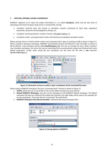
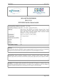
- Page 28 and 29: Note: Existing .sws files which hav
- Page 30 and 31: 4.1 Parameters of the Victim LinkTh
- Page 32 and 33: 4.3 Parameters of the Victim Receiv
- Page 34 and 35: Delta X = 2 kmyxVictimReceiver(Vr)d
- Page 36 and 37: Figure 25: Illustration on to check
- Page 38 and 39: Figure 28: Output display of SEAMCA
- Page 40 and 41: 5.2 Parameters of the General Tab o
- Page 42 and 43: 5.4 Positioning of the Vr vs ItSEAM
- Page 44 and 45: 5.5 Calculation of the iRSSFigure 3
- Page 46 and 47: Figure 37: Illustration of the emis
- Page 48 and 49: 6.1.1 Compatibility calculation mod
- Page 50 and 51: 7 STEP 4 : WHERE DOES THE INTERFERE
- Page 52 and 53: 7.2.2.1 User‐defined modeIn this
- Page 54 and 55: The same conclusion is reached by u
- Page 56 and 57: 8 STEP 5 : A REAL CASE …You will
- Page 58 and 59: Rwtmax 72 10 8 9= 1.42 kmFigure 57
- Page 60 and 61: The iRSS unwanted extends from ‐5
- Page 62 and 63: If 10 active terminals are located
- Page 64 and 65: 8.4 Protection distanceIf a minimum
- Page 66 and 67: 8.5 Power ControlNote: The power co
- Page 68 and 69: Using these assumptions, the result
- Page 70 and 71: Figure 80: Setting up the rotation
- Page 72 and 73: Figure 83: Definition of the batch
- Page 74 and 75: 9.2.2 Option 2: Auto‐generation o
- Page 76 and 77:
Figure 90: Example where 1 tier is
- Page 78 and 79:
Tip 4: Extraction of output vectors
- Page 80 and 81:
10.2 Pre‐simulation part10.2.1 De
- Page 82 and 83:
UplinkTarget Noise RiseMobile stati
- Page 84 and 85:
10.2.5 Initial CapacityThe capacity
- Page 86 and 87:
10.3 CDMA Simulation parts10.3.1 Ca
- Page 88 and 89:
10.3.2 Snapshot simulationOnce SEAM
- Page 90 and 91:
10.4 ResultsOnce SEAMCAT has comple
- Page 92 and 93:
11 OFDMA SIMULATIONNote: At the tim
- Page 94 and 95:
where N is the number of RBs (i.e.
- Page 96 and 97:
Figure 115: General OFDMA input par
- Page 98 and 99:
ParameterUser base stationDescripti
- Page 100 and 101:
Figure 121 presents the set‐up of
- Page 102 and 103:
12 EXAMPLE ‐ TETRA MS INTERFERERS
- Page 104 and 105:
Parameter Mobile Station Base Stati
- Page 106 and 107:
the wanted signal within the define
- Page 108 and 109:
Unwanted mask: Offset in MHz, power
- Page 110 and 111:
Annex 1 : EGE Input ParametersThis
- Page 112 and 113:
p. 51 Blocking response:Receiver fr
- Page 114 and 115:
A.1.4Window Victim link/Wanted tran
- Page 116 and 117:
Description: comments onthe linkInt
- Page 118 and 119:
A.1.7Window Interfering Link/ Wante
- Page 120 and 121:
page Description Symbol Type Unit C
- Page 122 and 123:
Uniform density:The user provides t
- Page 124 and 125:
Figure 140: Interfering link/It‐V
- Page 126 and 127:
ID Description Comments1 Calculatio
- Page 128 and 129:
1 condition1,0,if condition is sati
- Page 130 and 131:
Annex 3 : dRSS calculationIn this a
- Page 132 and 133:
Annex 4 : iRSS calculationFor the i
- Page 134 and 135:
A.5.1Unwanted emission MaskAnnex 5
- Page 136 and 137:
Eventually:emission _ relemission _
- Page 138 and 139:
Note:Delta = N1 (dBm/1 MHz) ‐ N2
- Page 140 and 141:
Figure 149: Illustration of the spe
- Page 142 and 143:
Annex 6 : Receiver selectivity and
- Page 144 and 145:
This limit of acceptable wanted sig
- Page 146 and 147:
A.6.5SEAMCAT calculation of receive
- Page 148 and 149:
Annex 7 : How to calculate the prob
- Page 150 and 151:
Annex 8 : Distribution or Function
- Page 152 and 153:
x X S / 2 ( i 1 Si min)wherei 1
- Page 154 and 155:
For the path azimuth used in descri
- Page 156 and 157:
By default all antennas have 0 dBi
- Page 158 and 159:
The coverage radius in the noise‐
- Page 160 and 161:
This function is aimed for the calc
- Page 162 and 163:
(a)Figure 174: Setting up the Power
- Page 164 and 165:
A.12.2 ACIR in DLIn DL ACIR ‐1 =A
- Page 166 and 167:
2. Run [number of trials] with 40 U
- Page 168 and 169:
ID Description1 Plot configuration
- Page 170 and 171:
A.13.2.3 Snapshot SummaryIt provide
- Page 172 and 173:
Figure 186: Main plot of CDMA netwo
- Page 174 and 175:
NameNon interferedcapacity per cell
- Page 176 and 177:
Name Description LinkdirectionGeome
- Page 178 and 179:
NameCell PositionUsing wraparounddi
- Page 180 and 181:
Name Description LinkdirectionCell
- Page 182 and 183:
Note: a full load system is assumed
- Page 184 and 185:
A.15.3 Free space propagation model
- Page 186 and 187:
General environmentLocal environmen
- Page 188 and 189:
Dist. Range Propagation mode Standa
- Page 190 and 191:
A.15.5 Spherical diffraction propag
- Page 192 and 193:
( f ) 10.5 1.5 ( f 57)57 < f 60
- Page 194 and 195:
When transmitter and receiver are l
- Page 196 and 197:
Frequency 100 MHz 600 MHz 2 000 MHz
- Page 198 and 199:
For d d H (h t ) the field strengt
- Page 200 and 201:
f: frequency (MHz).Note 1: The foll
- Page 202 and 203:
a tolerance of ε dB is to be used
- Page 204 and 205:
Figure 209: Access to the SEAMCAT c
- Page 206 and 207:
A.17.1 IntroductionAnnex 17 : Refer
- Page 208 and 209:
Victim Interferer Victim Interferer
- Page 210 and 211:
oThis is discussed but not included
- Page 212 and 213:
Annex 19 : Answers to the Tetra vs
- Page 214 and 215:
Propagation model Model:Hata Median
- Page 216 and 217:
Annex 21 : List of abbreviationsAbb
- Page 218 and 219:
transmitter (It)iRSSILTEInterfering
- Page 220 and 221:
LLibrary...........................
- Page 222:
Nansensgade 19, 31366 Copenhagen K,