Instructions - Glen Dimplex Ireland
Instructions - Glen Dimplex Ireland
Instructions - Glen Dimplex Ireland

Create successful ePaper yourself
Turn your PDF publications into a flip-book with our unique Google optimized e-Paper software.
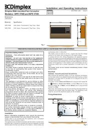
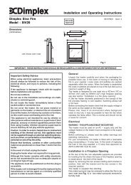
<strong>Dimplex</strong> Garage Fan HeaterModels : PFH30 and PFH30R (Remote Control)IMPORTANT : THESE INSTRUCTIONS SHOULD BE READ CAREFULLY AND RETAINED FOR FUTURE REFERENCEImportant Safety AdviceDO NOT COVER OR OBSTRUCT the air inlet or outlet grille.ENSURE THE PFH30R REMOTE CONTROL UNIT IS EARTHED.Always disconnect supply before working on the product.Always ensure combustible materials such as drapes orother furnishings are kept clear of the air inlet and air outlet.Never fit and use this heater in the immediate surroundingsof a bath, shower or swimming pool.Never leave the heater unattended when switched on nearto children, the aged or infirm.Do not use this heater in areas where excessive dust exists.This heater must not be located immediately above orbelow a fixed socket outlet or connection box.This product should be mounted safely to a solid wall.Ensure the supply cables are of adequate current carryingcapacity and are protected by a suitable fuse.This appliance should only be connected to the fixed wiringof the premises by means of conduit.This product must not be subjected to water spray orimmersion.WARNING: In order to avoid a hazard due to inadvertentresetting of the thermal cut-out, this appliance must not besupplied through an external switching device, such as atimer, or connected to a circuit that is regularly switchedon and off by the utility.GeneralThe PFH30 and PFH30R are high power wall mounted fanheaters providing environmental heating for smaller commercialenvironments such as garages and workshops.The heaters work by gradually raising the air temperature in agarage or workshop and should be positioned at head heightapproximately (1.8m - 2.3m - see Fig. 2) where the controls canbe easily reached.The PFH30 and PFH30R heaters have an output of 3kW.The angle the appliance is mounted at may be adjustedhorizontally and vertically - see Fig. 1 and Fig. 4.ElectricalThe installation of this appliance should be carried out by acompetent electrician and be in accordance with the current IEEwiring regulations. The supply cable is not supplied with theappliance.Note: A suitable local isolating switch must be provided in theelectrical supply circuit as close as possible to the heater with atleast 3mm clearance on each pole.Wall MountingRemove the screw (see ‘z’ in Fig. 3C) to remove the cover bracket.Use the wall mounting bracket (see ‘x’ in Fig. 3A) as a guide tomark off the hole positions on a suitable wall (a minimum heightof 1.8 metres is required from the floor level to the bottom hole ofthe bracket - see Fig. 2). Solid brick or concrete block walls mustbe drilled and plugged using the screws and wall plugs provided.Fix the wall mounting bracket to the wall and slide the heaterdown on to the bracket as shown in Fig. 3A.Note: Ensure there is enough clearance above the wall mountingbracket for the user to slide the heater onto the bracket.The heater is held in place to the wall mounting bracket with 2screws - see Fig. 3B.Once electrical connections have been completed - see ‘ElectricalInstallation’, re-attach the bracket cover (see ‘y’ in Fig. 3C) bysliding into place and secure with the screw - see ‘z’ in Fig. 3C.Pivot and rotate the heater into the desired position and tightenthe screw to secure - see ‘w’ in Fig. 4.Electrical InstallationBefore undertaking electrical installation, ensure the electricitysupply is disconnected from any relevant fixed wiring. With thebracket cover removed proceed to feed the supply cord throughthe cable entry at the bottom of the mounting bracket (drill knockoutto suit).PFH30R Remote Control - see Fig. 6Remove the wall mounting bracket from the remote control unit.Feed the supply cord through the desired cable entry (1-4 seeFig. 7). Connect the mains lead (ML) to terminal block - see Fig.6. Connect the 4 core cable (not supplied) from the remote controlto the appliance - see Fig. 6.Key - see Wiring Diagrams Fig. 5 -PFH30 & Fig. 6 -PFH30RRS Rotary Switch TB Terminal BlockML Mains Lead TB1 Terminal Block 1S1 Switch 1 TB2 Terminal Block 2S2 Switch 2 T ThermostatEL Element L LiveN Neutral E EarthL in Live In L out Live OutM Motor NEON NeonRC Remote Control GH Garage HeaterNote: All 4 core cable wires must be 1.5mm 2Controls - PFH30 - see Fig. 1The mains neon (see ‘b’ in Fig. 1) will light up to show that theheater is connected to the mains supply.Heat Control - see ‘a’ in Fig. 1The heat control positions are as follows:- OFF- Cool Blow*- Half heat- Full heatThermostat Control - see ‘c’ in Fig. 1The heat output is controlled by the thermostat, according to theroom temperature.Turn the thermostat knob fully clockwise to maximum settinginitially. When the room is warm enough, reduce the setting slowlyuntil the heater just clicks off.The heater will now cycle on and off to maintain your selectedroom temperature. An audible click may be heard when thethermostat operates - this is normal.Note : If the heater does not come on when the thermostat is ata low setting, this is normally because the room is warmer thanthe thermostat setting and is not a fault.* When the heat control is set to ‘ ’ for cool blow, set thethermostat control to maximum.Position ‘ ’ will turn the heater on and off to maintain atemperature of approximately 5°C.
Controls - PFH30RThe PFH30R is supplied with a wall mounted control unit. Thismay be mounted on a wall in a convenient location away fromdirect sunlight or draughty areas.Using the mounting bracket as a guide, mark the hole positionsand drill and plug the wall to suit using the screws and wallplugs provided.The heat output is controlled by the thermostat, according to theroom temperature.Turn the thermostat knob fully clockwise to maximum settinginitially. When the room is warm enough, reduce the setting slowlyuntil the heater just clicks off.The heater will now cycle on and off to maintain your selectedroom temperature. An audible click may be heard when thethermostat operates - this is normal.Note : If the heater does not come on when the thermostat is ata low setting, this is normally because the room is warmer thanthe thermostat setting and is not a fault.* When the heat control is set to ‘ ’ for cool blow, set thethermostat control to maximum.Position ‘ ’ will turn the heater on and off to maintain atemperature of approximately 5°C.Thermal Safety Cut-outsThe power supply to the heater may also be interrupted if one ora combination of the following abnormal events occurs:1. Air inlet or outlet grilles are obstructed.2. Internal ventilation is impaired due to build up of dust andfluff.3. Blower unit stalls.In the event that the above events occur the cut-out switches offthe heater automatically. To bring the heater back into operation,remove the cause of the overheating, then turn off the electricalsupply to the heater for a few minutes. When the heater hascooled sufficiently re-connect and switch on the heater.If the cut-out operates repeatedly, contact your supplier.RecyclingFor electrical products sold within the EuropeanCommunity.At the end of the electrical products useful life itshould not be disposed of with household waste.Please recycle where facilities exist. Check withyour Local Authority or retailer for recycling advicein your country.CleaningWARNING: DISCONNECT SUPPLY before carrying outmaintenance.External appearance can be maintained by wiping occasionallywith a damp cloth. For stain removal, a weak soap solution canbe applied with a cloth and the surface wiped dry. Care must betaken to avoid any moisture ingress into the product.After Sales ServiceYour product is guaranteed for one year from the date of purchase.Within this period, we undertake to repair or exchange this productfree of charge (excluding element & subject to availability)provided it has been installed and operated in accordance withthese instructions.Your rights under this guarantee are additional to your statutoryrights, which in turn are not affected by this guarantee.Should you require after sales service you should contact ourcustomer services help desk on 0845 600 5111. It would assistus if you can quote the model number, series, date of purchase,and nature of the fault at the time of your call. The customerservices help desk will also be able to advise you should youneed to purchase any spares.Please do not return a faulty product to us in the first instance asthis may result in loss or damage and delay in providing you witha satisfactory service.Please retain your receipt as proof of purchase.<strong>Glen</strong> <strong>Dimplex</strong> UK LimitedMillbrook HouseGrange DriveHedge EndSouthamptonHampshire. SO30 2DFUK customer help line (8.00AM – 6.00PM Mon-Fri; 8.30AM-1.00PM Sat)Customer Services: Tel. 0845 600 5111Fax. 01489 773053e-mail customer.services@glendimplex.comRepublic of <strong>Ireland</strong> Tel. 01 8424833[c] <strong>Glen</strong> <strong>Dimplex</strong> UK LimitedAll rights reserved. Material contained in this publication may not be reproduced in whole or in part, without prior permission in writing of <strong>Glen</strong> <strong>Dimplex</strong> UK Limited.