Smart-Bus G4 Power Meter Installation Manual Features ...
Smart-Bus G4 Power Meter Installation Manual Features ...
Smart-Bus G4 Power Meter Installation Manual Features ...

Create successful ePaper yourself
Turn your PDF publications into a flip-book with our unique Google optimized e-Paper software.
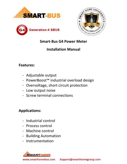
<strong>Smart</strong>-<strong>Bus</strong> <strong>G4</strong> <strong>Power</strong> <strong>Meter</strong><strong>Installation</strong> <strong>Manual</strong><strong>Features</strong>:- Adjustable output- <strong>Power</strong>Boost industrial overload design- Overvoltage, short circuit protection- Low output noise- Screw terminal connectionsApplications:- Industrial control- Process control- Machine control- Building Automation- Instrumentation
DiagramLayout
Diagram Layout Description:1- Single Phase supply terminal: consist of One terminal for Neutral and3 other terminals for the Three phases (R Y B) that are needed to bemonitored. Theses terminal are used to read the AC Voltage value ofthe phases.2- Load connection: for Phases R and Y, IN and OUT. The connectionterminals for the loads in order to calculate the amount of amperebeing consumed per each phase.3- Load connection for Phase B.4- <strong>Bus</strong> connection locker: this Locker used to tight 2 modules togetherwhen using the train bus terminal connections, make the busconnection more safe and strong.5- Normal <strong>Bus</strong> connation terminal: it is a screw based terminals toconnect the module to other bus module in the RS485 bus networkusing the old G3 terminals type. Recommended Wires to use for thisTerminals connection is: 4 wires of the cat5e cable.6- Train bus connection: it is new method developed in this <strong>G4</strong> moduleto connect 2 <strong>G4</strong> Din Rail modules to each other without using anyscrew drivers or extra wires, making the bus connection faster andmore accurate.7- USB Port: this <strong>G4</strong> new Module is provided with USB Port as anupgrading terminal that can easily connect to any PC USB port for anynew features upgrading that keep the module up to date.
Connection Diagram:Above is an example of connecting two different loads on different phasesto the <strong>Smart</strong> <strong>G4</strong> power meter.The load power cable is passing through the <strong>G4</strong> <strong>Power</strong> <strong>Meter</strong> terminal, inorder to read the information and process it.NOTE: The Current terminals of the <strong>Smart</strong> <strong>G4</strong> <strong>Power</strong> <strong>Meter</strong> can handle upto 5 Amps only. Do not connect to it load that is more than 5 Amps.Using Current Transformers:In cases of higher loads than 5 amps, you can use any current transformer(CT) that would output a decreased current.See below Photos and description Of one recommended type of CT:
What is Current Transformers (CTs)?A current transformer is a device for measuring a current flowing through apower system and inputting the measured current to a protective relaysystem. Electrical power distribution systems may require the use of avariety of circuit condition monitoring devices to facilitate the detectionand location of system malfunctions.A current transformer consists of primary and secondary coils of wirewrapped around a core, usually made of steel or a nickel alloy. Transformerwindings are electrically insulated from each other and from the core. Thewinding connected to the power supply is called the primary winding. Thetransformer winding in which current is induced is called the secondarywinding.
There are different types and scales of Low Current transformers. You canfind ones that transforms the Current from 200 Amps, 100 Amps or 50Amps to 5 Amps or less.Depending on the maximum <strong>Power</strong> consumed on each phase (ALL LOADSARE ON IN THE SAME TIME+ALL TYPES OF LOADS ARE ON IT IS MAXINUMPOWER CONSUMPTION FEATURE) you should choose carefully your CT, andtest before connecting to the <strong>Smart</strong> <strong>G4</strong> <strong>Power</strong> <strong>Meter</strong>.
Conclusion:Having connected your transformers and terminating it to the <strong>Smart</strong> <strong>G4</strong><strong>Power</strong> <strong>Meter</strong>, Now you can configure the Module like any other <strong>G4</strong> SbusModule, Get the ID address (like using Broadcast button).To fetch the Data that the <strong>Power</strong> <strong>Meter</strong> Module is reading in the HACprogram for example, you just need to add the Address that you chose foryour power meter. Check the picture below:
Interval time:Is the information reading and calculating rate done by the <strong>Power</strong> <strong>Meter</strong>Module. 1 sec means that every 1 sec the <strong>Meter</strong> will fetch new powerinformation and calculate the <strong>Power</strong> consumed and diplay itClear the Electricity Degree:Resetting the Data already collected for previous sessions to zero.Rate of the current and power:According to the Current transformer you are using u should choose thisvalue. It is the Ratio of the actual current consumed by the loads, to thecurrent generated by the current transformer. This is used to get thecurrent reading back to the actual current consumed before it is decreasedby the CT.
In the <strong>Smart</strong> <strong>G4</strong> HAC software for Windows, just go to settings -> powermeter -> Enter the Device ID of your power meter Module. And press save.It will do the reading for you.Alarm current when it is bigger than the specified value, is used to alert theuser if the power consumption reaches a critical value.