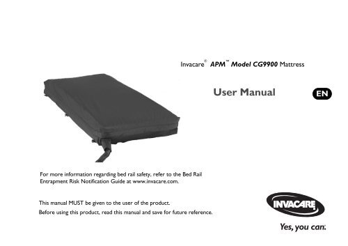
Owner's Manual - Invacare
Owner's Manual - Invacare
Owner's Manual - Invacare

You also want an ePaper? Increase the reach of your titles
YUMPU automatically turns print PDFs into web optimized ePapers that Google loves.
1 GENERAL1.2 Limited WarrantyPLEASE NOTE: THE WARRANTY BELOW HAS BEEN DRAFTED TO COMPLY WITH FEDERAL LAW APPLICABLE TO PRODUCTSMANUFACTURED AFTER JULY 4, 1975.This warranty is extended only to the original purchaser who purchases this product when new and unused from <strong>Invacare</strong> or a dealer. This warranty isnot extended to any other person or entity and is not transferable or assignable to any subsequent purchaser or owner. Coverage under this warrantywill end upon any such subsequent sale or other transfer of title to any other person.This warranty gives you specific legal rights and you may also have other legal rights which vary from state to state.<strong>Invacare</strong> warrants the mattress and cover when purchased new and unused to be free from defects in materials and workmanship for a period of oneyear from the date of purchase from <strong>Invacare</strong> or a dealer, with a copy of the seller’s invoice required for coverage under this warranty. <strong>Invacare</strong>warrants the control unit when purchased new and unused to be free from defects in materials and workmanship for a period of one year from the dateof purchase from <strong>Invacare</strong> or a dealer, with a copy of the seller’s invoice required for coverage under this warranty. If within such warranty period anysuch product shall be proven to be defective, such product shall be repaired or replaced, at <strong>Invacare</strong>'s option, with refurbished or new parts. Thiswarranty does not include any labor or shipping charges incurred in replacement part installation or repair of any such product. Product repairs shallnot extend this warranty - coverage for repaired product shall end when this limited warranty terminates. <strong>Invacare</strong>'s sole obligation and your exclusiveremedy under this warranty shall be limited to such repair and/or replacement.For warranty service, please contact the dealer from whom you purchased your <strong>Invacare</strong> product. In the event you do not receive satisfactory warrantyservice, please write directly to <strong>Invacare</strong> at the address on the back cover. Provide dealer's name, address, model number, and the date of purchase,indicate nature of the defect and, if the product is serialized, indicate the serial number.<strong>Invacare</strong> Corporation will issue a return authorization. The defective unit or parts must be returned for warranty inspection using the serial number,when applicable, as identification within thirty days of return authorization date. DO NOT return products to our factory without our prior consent.C.O.D. shipments will be refused; please prepay shipping charges.LIMITATIONS AND EXCLUSIONS: THE WARRANTY SHALL NOT APPLY TO PROBLEMS ARISING FROM NORMAL WEAR OR FAILURE TOADHERE TO THE ENCLOSED INSTRUCTIONS. IN ADDITION, THE FOREGOING WARRANTY SHALL NOT APPLY TO SERIAL NUMBEREDPRODUCTS IF THE SERIAL NUMBER HAS BEEN REMOVED OR DEFACED; PRODUCTS SUBJECTED TO NEGLIGENCE, ACCIDENT,IMPROPER OPERATION, MAINTENANCE OR STORAGE; OR PRODUCTS MODIFIED WITHOUT INVACARE'S EXPRESS WRITTEN CONSENTINCLUDING, BUT NOT LIMITED TO: MODIFICATION THROUGH THE USE OF UNAUTHORIZED PARTS OR ATTACHMENTS: PRODUCTSDAMAGED BY REASON OF REPAIRS MADE TO ANY COMPONENT WITHOUT THE SPECIFIC CONSENT OF INVACARE; PRODUCTSDAMAGED BY CIRCUMSTANCES BEYOND INVACARE'S CONTROL; PRODUCTS REPAIRED BY ANYONE OTHER THAN AN INVACAREDEALER, SUCH EVALUATION SHALL BE SOLELY DETERMINED BY INVACARE.THE FOREGOING EXPRESS WARRANTY IS EXCLUSIVE AND IN LIEU OF ALL OTHER EXPRESS WARRANTIES WHATSOEVER, WHETHEREXPRESS OR IMPLIED, INCLUDING THE IMPLIED WARRANTIES OF MERCHANTABILITY AND FITNESS FOR A PARTICULAR PURPOSEAND THE SOLE REMEDY FOR VIOLATIONS OF ANY WARRANTY WHATSOEVER, SHALL BE LIMITED TO REPAIR OR REPLACEMENT OFTHE DEFECTIVE PRODUCT PURSUANT TO THE TERMS CONTAINED HEREIN. THE APPLICATION OF ANY IMPLIED WARRANTYWHATSOEVER SHALL NOT EXTEND BEYOND THE DURATION OF THE EXPRESS WARRANTY PROVIDED HEREIN. INVACARE SHALLNOT BE LIABLE FOR ANY CONSEQUENTIAL OR INCIDENTAL DAMAGES WHATSOEVER.THIS WARRANTY SHALL BE EXTENDED TO COMPLY WITH STATE/PROVINCIAL LAWS AND REQUIREMENTS.Part No 1171739 5 <strong>Invacare</strong> ® APM Model CG9900 Mattress
2 OVERVIEW2 Overview2.1 Label LocationDANGER-EXPLOSION HAZARD: DO NOTuse in the presence of flammable anesthetics.CAUTION: Equipment should be connected to aproperly grounded receptacle (3-prong). Risk ofElectrical shock. DO NOT remove back. Disconnectair hose before administering CPR.<strong>Invacare</strong> ® APM Model CG9900 Mattress 6 Part No 1171739
2.2 Typical Product ParametersElectrical Parameters2 OVERVIEWINPUT VOLTAGE AC:INPUT FREQUENCY:CURRENT:MAXIMUM POWER CONSUMPTION:CIRCUIT PROTECTION:MODE OF OPERATION:Performance ParametersCG990090 V60 Hz1 A5 ± 3 WDual fused, 250 V, 1 A fast blow fusesContinuousCG9900CG9900WEIGHT CAPACITY:PRESSURE ZONE:MAXIMUM FLOW:MAXIMUM FLOW PRESSURE:MAXIMUM FLOW TIMER:SUPPORT SURFACE INFLATIONTIME:350 lbs212 ± 4 LPM35 ± 5 mmHg45 minutes20 - 45 minutesPATIENT COMFORTCONTROLPRESSURESSOFT PRESSURE:FIRM PRESSURE:CYCLE TIME:8 ± 4 mmHg32 ± 4 mmHg10 minutesPATIENT CONTACT:Control unit and mattresshave Latex-Free componentsPart No 1171739 7 <strong>Invacare</strong> ® APM Model CG9900 Mattress
2 OVERVIEWMechanical ParametersCONTROL UNITDIMENSIONS(L X W X H):WEIGHT:POWER CORD:CONNECTION:PACKAGING:AIR FILTER:Environmental ParametersCG99009” x 4.5” x 5”5 lbs10 - 14 Feet Long, HospitalGradeTwo ¼” Flow Couplings1 piece/boxNoneCG9900OPERATING CONDITIONSAMBIENT TEMPERATURE:RELATIVE HUMIDITY:ATMOSPHERIC PRESSURE:STORAGE AND SHIPPING CONDITIONSAMBIENT TEMPERATURE:RELATIVE HUMIDITY:ATMOSPHERIC PRESSURE:50° - 104° F30% - 75% Non-Condensing70 - 106 kPa-40° - 158° F10% - 100% Non-Condensing50 - 106 kPa<strong>Invacare</strong> ® APM Model CG9900 Mattress 8 Part No 1171739
3 Safety3 SAFETY3.1 General Guidelines! NOTICETHE INFORMATION CONTAINED IN THIS DOCUMENT IS SUBJECT TO CHANGE WITHOUT NOTICE.Check all parts for shipping damage and test before using. In case of damage, DO NOT use. Contact <strong>Invacare</strong>/Carrier forfurther instruction.ContraindicationsWARNINGALWAYS consult the patient’s physician before using the CG9900 system.ElectricalDANGERElectrical shock hazard. DO NOT remove cover. Refer to qualified service personnel.WARNINGBefore performing any maintenance to the power unit, disconnect the power cord from the wall outlet.DO NOT insert items into any openings of the control unit. Doing so may cause fire or electric shock by shorting theinternal components.The control unit MUST be kept away from all heat sources and radiators during operation.Connect the equipment to properly grounded three prong wall outlet using 10-14 ft hospital grade power cord providedwith the product.Grounding reliability depends upon a properly grounded receptacle (3-prong).Part No 1171739 9 <strong>Invacare</strong> ® APM Model CG9900 Mattress
3 SAFETYInstallationWARNINGThe CG9900 system is recommended to be installed on medical bed frames with bed side or assist rails. It is preferred thatthe rails be in the raised position whenever a patient is on the bed. Health care professionals assigned to each case shouldmake the final determination whether side or assist rails are warranted after assessing patient risks of entrapment and fallsin accordance with State patient restraint legislation or facility interpretation of such legislation.Controls on the footboard may be obstructed by the power unit on a few bed frames. It may be necessary to relocate thepower unit. Refer to Installing the Power Unit on page 14.Check that air hoses and power cord are clear of moving bed components before placing a patient on the bed. Operate allbed frame motorized functions through their full range of motion to be certain that there is no pulling, interference orpinching.DO NOT strap the mattress to the bed frame at the head and foot ends. Secure ALL mattress straps. Secure the strapsto the bed deck at the head and foot ends and to the frame at the center of the bed. Otherwise damage to the mattresswill occur when the head and foot ends are raised. Refer to Mattress Replacement System on page 13.<strong>Invacare</strong> ® APM Model CG9900 Mattress 10 Part No 1171739
Entrapment May OccurDANGERFire Hazard- Smoking3 SAFETYPatient entrapment with bed side rails may cause injury or death. Mattress MUST fit bed frame and side rails snugly toprevent patient entrapment. Follow the manufacturer’s instructions. Monitor patient frequently. Read and understand theOwner’s/Operator’s <strong>Manual</strong> prior to using this equipment. <strong>Invacare</strong> product manuals are available at www.invacare.com oryour dealer.Proper patient assessment and monitoring, and proper maintenance and use of equipment is required to reduce the risk ofentrapment. Variations in bed rail dimensions, and mattress thickness, size or density could increase the risk of entrapment.Visit the FDA website at http://www.fda.gov to learn about the risks of entrapment. Review “A Guide to Bed Safety”,published by the Hospital Bed Safety Workgroup, located at www.invacare.com. Use the link located under each bed railproduct entry to access this bed safety guide.Refer to the owner’s manuals for beds and rails for additional product and safety information.After any adjustments, repair or service and before use, make sure all attaching hardware is tightened securely. Assist railswith dimensions different from the original equipment supplied or specified by the bed manufacturer may not beinterchangeable and may result in entrapment or other injury.DANGERDO NOT SMOKE while using this device. A cigarette can burn a hole in the bed surface and cause damage to the mattress.Also, patient clothing, bed sheets, etc. may be combustible and cause a fire. Failure to observe this warning can result insevere fire, property damage and cause physical injury or death.Smoking by visitors in the room will contaminate the system. Therefore, visitor smoking is NOT permitted.Part No 1171739 11 <strong>Invacare</strong> ® APM Model CG9900 Mattress
3 SAFETYFire Hazard - Anesthesia EquipmentDANGERThere is an explosion risk if used with flammable anesthetics.Fire Hazard - OxygenDANGERThere is a possible fire hazard when used with oxygen administering equipment other than nasal mask or half bed tent type.The oxygen tent should NOT extend below mattress support level.<strong>Invacare</strong> ® APM Model CG9900 Mattress 12 Part No 1171739
4 Operation4.1 Mattress Replacement System1. Remove the original mattress from the bed.2. If necessary, lower the side rails to facilitate installation of themattress.3. Unroll the powered mattress and place it on the bed frame.CAUTION4. Use the buckle straps to secure the powered mattress to the beddeck in the following locations:• Head End - Head End Bed Deck• Foot End - Foot End Bed Deck• Center - Center of the Bed Frame4 OPERATIONDO NOT strap the mattress to the bed frame at the head and foot ends. Secure ALL mattress straps. Secure the strapsto the bed deck at the head and foot ends and to the frame at the center of the bed. Otherwise damage to the mattresswill occur when the head and foot ends are raised.The powered mattress comes with eight nylon buckle straps.Ensure that the hose is towards the foot end of thebed.HeadEndBuckleStrapsHosePowered MattressFoot EndFIGURE 1 Mattress Replacement System - Mattress ReplacementSystemPart No 1171739 13 <strong>Invacare</strong> ® APM Model CG9900 Mattress
4 OPERATION4.2 Installing the Side RailsWARNINGPatient entrapment with bed side rails may cause injury or death. Mattress MUST fit bed frame and side rails snugly toprevent patient entrapment. Follow the manufacturer’s instructions. Monitor patient frequently. Read and understand theOwner’s/Operator’s <strong>Manual</strong> prior to using this equipment. <strong>Invacare</strong> product manuals are available at www.invacare.com oryour dealer.Refer to the instructions provided with the side rails for the installation procedure.Installing the Power Unit1. Swing out the bed hooks on the back of the control unit.2. Place the control unit on the footboard.Bed HooksIf the bed does not have a footboard, place thecontrol unit on a flat surface, leaving room for thehose to hang down.FIGURE 2 Installing the Power Unit<strong>Invacare</strong> ® APM Model CG9900 Mattress 14 Part No 1171739
4.3 Connecting the Hose1. Locate the hose at the foot end of the mattress.2. Locate the control unit connectors on the right side of the control unit.3. Squeeze and hold the tabs on the hose connectors.4. Push the hose connectors onto the control connectors until an audible click is heard.CAUTION4 OPERATIONEnsure that the hose connecting the control unit to the mattress is routed such that it cannot be stepped on, kinked,squeezed or otherwise damaged.The audible click indicates that the hose connectors are properly engaged with the control connectors.Control Unit ConnectorsHosesTabHoseConnectorFIGURE 3 Connecting the HosePart No 1171739 15 <strong>Invacare</strong> ® APM Model CG9900 Mattress
4 OPERATION4.4 Connecting the Power Cord1. Examine the hospital grade power cord supplied with the control unit.2. Perform one of the following:• If the cord is damaged - Call your supplier for a replacement hospital grade cord.• If the cord is not damaged - Plug the end of the supplied hospital grade power cord into the power outlet on the side of the control unit.3. Plug the other end of the plug into a properly grounded outlet on the wall.WARNINGDO NOT alter plug to fit a non-conforming outlet. Instead, have an electrician install a properly grounded 3-prong outlet.Failure to use the correct plug and outlet can result in a potential safety hazard.CAUTIONEnsure that the power cord of the control unit is not pinched, or has any objects placed on it, and also ensure it is notlocated where it can be stepped on or tripped over.Once the unit is plugged in, an amber LED on the control unit is lit indicating that the system is in STAND BY mode.<strong>Invacare</strong> ® APM Model CG9900 Mattress 16 Part No 1171739
4.5 Using the Front Panel4 OPERATIONPower Fail LED/Low PressureLEDSoft ButtonPower ButtonFIGURE 4 Using the Front Panel1. To turn the control unit on or off, press and release the Power button.Static/AlternatingPressure and MaxFirm ButtonPower ButtonLCD DisplayFirm ButtonOnce the unit is plugged in, an amber LED on the control unit is lit indicating that the system is in stand by mode. Once thePower button is pressed and released, a green LED on either AP or Static or Max Firm illuminates indicating that thecontrol unit is on.If the power comes on after a power outage, the control unit will go through its system initialization routine for a fewseconds and then resume the desired function.Part No 1171739 17 <strong>Invacare</strong> ® APM Model CG9900 Mattress
4 OPERATIONFirm/Soft Buttons1. Select comfort pressure settings by pressing Firm ( ) or Soft ( ) button.• Soft Button - Pressing this button reduces the pressure setting in the mattress.• Firm Button - Pressing this button increases the pressure setting in the mattress.The patient comfort pressure ranges from Soft (level 0 = 8±4 mmHg) to Firm (level 9 = 32±4 mmHg). The ComfortControl LED displays the patient comfort pressure levels from 0 to 9 and provides a guide to the caregiver to setapproximate comfort pressure level depending on the patient weight. If the patient’s weight to height ratio is above average,increase the pressure setting by approximately 20% or raising the control setting by 1 or 2 above the expected setting forthat weight.Recommended Pressure Settings1. For rapid inflation of the mattress, activate “Max Firm” (by following the “Max Firm” instructions).2. For extra firm support during patient ingress/egress, patient wound care, patient turning or patient cleaning, it is recommended to set themattress pressure to Max Firm.Max Firm1. Activate Max Firm by pressing mode key: ( ). Max Firm LED will light up this mode. The Max Firm is used to rapidly inflate the mattress.Max Firm Mode will deactivate after 44 minutes, at which point the LED will turn off and the unit will default to its previous setting. In this modethe entire mattress will be pressurized to 35+/- 5 mm Hg.It takes 40-60 minutes for the mattress to inflate fully (inflation time depends on size of mattress).It is recommended that Max Firm setting be used during patient ingress/egress, patient wound care, patient turning or patientcleaning.<strong>Invacare</strong> ® APM Model CG9900 Mattress 18 Part No 1171739
Static4 OPERATION1. To set static mode, press the “Mode” key until the “Static” LED is lit. In static mode, all the air cushions in the mattress will be maintained atconstant pressure.Alternating Pressure1. To set alternating pressure (A/P) mode, press the "Mode" key until the "A/P" alternating pressure LED is lit.2. In the A/P mode, the even numbered air cushions in the mattress will deflate, while the odd numbered cushions remain at constant pressure.When 10 minutes has elapsed, the even numbered air cushions will inflate while the odd numbered cushions remain at constant pressure. When10 minutes has elapsed again, the odd numbered air cushions deflate while the even numbered cushions remain at constant pressure. The aircushions continue to inflate or deflate like this as long as the alternating pressure mode is selected.Adjusting the Minimum Pressure Setting (A/P Low)The minimum pressure setting during alternating pressure is set to 0 (3mm Hg) at the factory. This means the mattress will deflate as much as possibleduring the deflation time when using the "A/P" mode. The setting can be changed so the mattress will only deflate to 50% of the selected pressuresetting.1. Ensure the standby LED is lit.2. Perform the following:• Press and hold the "Firm" and "Mode" keys while in standby.3. Read the LCD display. The LCD display will flash:• UNIT WILL DISPLAY "0" FOR LOW A/P SET TO 0 (3 mmHg)• UNIT WILL DISPLAY "5" FOR LOW A/P SET TO 50% OF HIgh4. Perform one of the following to toggle between the two settings• PRESS MODE KEY TO TOGGLE LOW SIDE A/P PRESSURE• PRESS ON/STANDBY KEY TO END ROUTINEPart No 1171739 19 <strong>Invacare</strong> ® APM Model CG9900 Mattress
4 OPERATION4.6 Failure ModesPower Fail LEDIn the event of power outage, Power Fail LED flashes AMBER. The control unit has internal memory and retains the previous settings during the poweroutage.Low Pressure LEDIn the event that the mattress hose disconnects, or low pressure is detected, an alarm sounds and Low Pressure LED flashes AMBER. Once the lowpressure problem is fixed, the control unit resumes operation in the previously set mode.1. The mattress will hold air during transportation or power failure as long as the mattress is connected to the control unit.4.7 Powering Up the System For this procedure, refer to FIGURE 4 on page 17.1. Turn on the power to the system by pressing the Power button on the control unit.During a power outage, the mattress retains the air as long as the mattress is connected to the control unit.4.8 Placing the Patient on the Mattress1. Press the Mode button to select Max Firm Mode.Once the button is released, a green LED illuminates when the unit is on.In this mode, the Max Firm LED lights up.2. After the mattress is fully inflated, place the patient on the mattress.3. Ensure that the patient’s feet are towards the foot end of the mattress (the end with the hose).<strong>Invacare</strong> ® APM Model CG9900 Mattress 20 Part No 1171739
4. Center the patient on the bed from side-to-side and head-to-foot.Special positioning may be required with contracted patients to provide comfortable positions.5. After placing the patient, make certain no objects will fall under the patient, such as feeding tubes, IV's etc.6. Wait five minutes for the mattress pressure to stabilize.7. Once the mattress inflates to its normal size, set the comfort pressure to the desired comfort level.8. Wait five minutes for the mattress pressure to stabilize.9. Verify that the patient has not bottomed out by performing the following steps:A. Ensure that the patient is lying flat on his/her back in the middle of the mattress.B. Place four fingers between the air cushions directly underneath the sacral region of the patient’s body.C. Ensure that there is 3 to 4-finger width clearance between the bottom of the patient and the bed frame.D. Adjust the comfort setting, if needed.E. Wait five minutes for the mattress pressure to stabilize.F. Repeat STEPS A-E until patient has not bottomed out and patient comfort is achieved.10. If the patient feels that the bed is too soft/hard, press the Soft or Firm button to adjust the comfort settings.11. Use a regular pillow to help support and stabilize the patient's head.4 OPERATION4.9 Transferring Patient From/To a GurneyWARNINGALWAYS engage the wheel locks of the bed and the wheel locks of the gurney before transferring the patient between thebed and the gurney.1. Engage the wheel locks of the bed. Refer to the owner’s manual provided with the bed.2. Engage the wheel locks of the gurney. Refer to the owner’s manual provided with the gurney.3. Press the Max Firm or Mode button to achieve maximum mattress pressure.Part No 1171739 21 <strong>Invacare</strong> ® APM Model CG9900 Mattress
4 OPERATION4. Raise or lower the bed to match the gurney height. Refer to the owner’s manual provided with the bed.5. When the mattress has reached maximum firmness, perform one of the following:• Bed to Gurney Transfer - Slide the patient onto the gurney.• Gurney to Bed Transfer - Slide the patient onto the bed.4.10 Transferring Patient From/To a WheelchairWARNINGALWAYS engage the wheel locks of the bed and the wheel locks of the wheelchair before transferring the patient betweenthe bed and the wheelchair.1. Engage the wheel locks of the bed. Refer to the owner’s manual provided with the bed.2. Engage the wheel locks of the wheelchair, if applicable. Refer to the owner’s manual provided with the wheelchair.3. Press the Max Firm or Mode button to achieve maximum mattress pressure.4. Raise or lower the bed to match the wheelchair height. Refer to the owner’s manual provided with the bed.5. When the mattress has reached maximum firmness, perform one of the following:• Bed to Wheelchair Transfer - Slide the patient onto the wheelchair.• Wheelchair to Bed Transfer - Slide the patient onto the bed.4.11 Preparing for CPR Procedure For this procedure, refer to FIGURE 5.1. Press and hold the tabs on hose connector while pulling the hose from the control unit.<strong>Invacare</strong> ® APM Model CG9900 Mattress 22 Part No 1171739
4 OPERATIONControl Unit ConnectorsMattressTabHoseConnectorHoses4.12 About Power Outage and TransportationFIGURE 5 Preparing for CPR ProcedureIf the hoses remain connected to the control unit, the mattress retains air during a power outage, during transportation, when the control unit isunplugged or when the control unit is turned Off.Part No 1171739 23 <strong>Invacare</strong> ® APM Model CG9900 Mattress
5 MAINTENANCE AND TROUBLESHOOTING5 Maintenance and Troubleshooting5.1 Cleaning the SystemWARNINGBefore cleaning or disassembling the CG9900 mattress, check the underside of the mattress folds for sharp objects such asscissors, needles, etc. These objects should be removed and discarded before proceeding with further cleaning ordisassembly; otherwise injury or damage to the product may occur.Because of potential risk of infectious exposure, cleaning with the patient on the bed is not recommended.All equipment should be inspected. Any item that is visibly soiled with the patient's blood or other body fluids should beproperly cleaned or removed.Laundry workers should treat all soiled bedding as if it were contaminated with pathogenic microorganisms.1. Remove the bedding.2. If necessary, inflate the mattress.3. Ensure that the control unit is off.4. Unplug the power cord from the wall outlet.5. Ensure that the underside of the mattress is clear of all sharp objects.6. Examine the surface of the control unit and mattress assembly components for visible blood or body fluids.7. Perform one of the following:• If blood is present, decontaminate the product.i. Remove all visible soil with disposable paper towels.ii. Scrub the area with freshly prepared effective phenolic detergent disinfectant solution.<strong>Invacare</strong> ® APM Model CG9900 Mattress 24 Part No 1171739
• If blood is not present, remove any soil from the cover with paper towels.If soiled, the cover should be removed, cleaned and decontaminated.5 MAINTENANCE AND TROUBLESHOOTING8. Perform the following steps to clean the mattress cover:A. Using a clean sponge or paper towel, Scrub the area with freshly prepared effective phenolic detergent disinfectant solution.B. Remove the cover and launder it using the following method:CAUTIONLaundry workers should always wash their hands before working with clean bedding.DO NOT overload the machine.DO NOT use chlorine bleach because it may damage the fabric coating.High air temperatures will damage the fabrics and void the <strong>Invacare</strong> warranty.i. Place the cover in a washing machine.ii. Wash with warm water (below 120°F).iii. Add detergent and disinfectant according to the manufacturer’s instructions.iv. Remove excess water.v. Set the dryer to the lowest setting (below 120°F).vi. Dry the cover until it is completely dry.9. Perform the following steps to clean the control unit and hose fittings:A. Wipe all controls, chassis and hose fittings with a quaternary disinfectant solution.B. Using a nylon brush, gently clean all crevices as they can harbor microorganisms.C. Air dry all treated surfaces.Part No 1171739 25 <strong>Invacare</strong> ® APM Model CG9900 Mattress
5 MAINTENANCE AND TROUBLESHOOTING10. Perform the following steps to clean the mattress components (air cushions, mattress base, etc.):A. Using a clean sponge or paper towel, wipe down the mattress components with a dilute detergent solution of quaternary cleaner disinfectantor other germicidal detergent solution.B. Wipe the mattress components with a clean dry cloth.Storing the System1. Ensure that the control unit is off and disconnect the power cord from the wall outlet.2. Clean the system. Refer to Cleaning the System on page 24.3. Disconnect the air hose connector(s) from the control unit and allow air to vent from the mattress.4. Gently roll up the mattress with minimal handling and agitation.5. Ensure the cover surface is inside the roll.6. Store the unit, keeping the mattress with the control unit.Replacing BladdersTo replace an individual bladder:1. Unsnap the buttons for the bladder on both sides.2. Cut a small slit on the red female connector.3. Pull apart the cut female end of the connector and bladder from the male end of the manifold.4. Take the new bladder and dampen the inside of the female end of the connector.5. Push the new female end of the connector and bladder onto the male end of the manifold securely.<strong>Invacare</strong> ® APM Model CG9900 Mattress 26 Part No 1171739
5.2 Troubleshooting5 MAINTENANCE AND TROUBLESHOOTINGPROBLEM CAUSE SOLUTIONMattress not inflating Mattress hose disconnectedConnect hose connectors and lock them in placeNot alternating properlyAir hose kinked or splitUnkink hose or replace split hoseMajor leak in the air cushionsReplace leaking air cushionsKinked or split manifoldUnkink manifold or replace split manifoldHas power and fuse is good, control unit does not come on Send control unit back to factory for repairNot alternating, solenoid malfunctionSend control unit back to factory for repairNo air, pump malfunctionSend unit for repairNo power Control unit off Check power source and turn on unitPower cord disconnectedConnect power cord to the power sourceNo power in the power sourceCheck power source has power and turn it OnPower outageWait till the power source has powerBlown fuseReplace blown fuse with an equivalent fusePart No 1171739 27 <strong>Invacare</strong> ® APM Model CG9900 Mattress
<strong>Invacare</strong> CorporationUSAOne <strong>Invacare</strong> WayElyria, Ohio USA44036-2125800-333-6900Part No 1171739 Rev A - 2/11 www.invacare.comCanada570 Matheson Blvd EUnit 8Mississauga OntarioL4Z 4G4 Canada800-668-5324