FREQUENCY DETECTION MODULE (FDM) - Frontier Power Products
FREQUENCY DETECTION MODULE (FDM) - Frontier Power Products
FREQUENCY DETECTION MODULE (FDM) - Frontier Power Products

You also want an ePaper? Increase the reach of your titles
YUMPU automatically turns print PDFs into web optimized ePapers that Google loves.
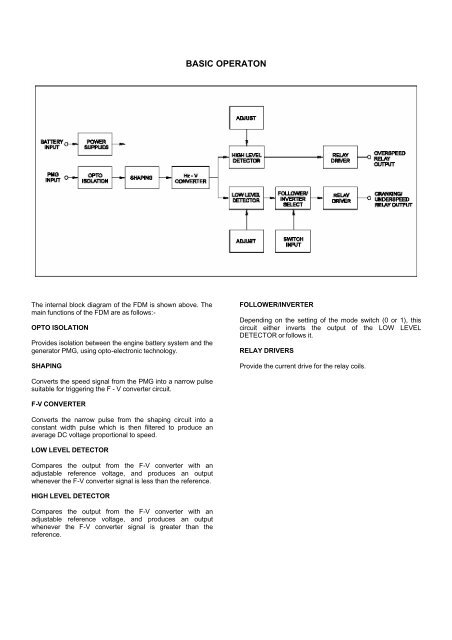
BASIC OPERATONThe internal block diagram of the <strong>FDM</strong> is shown above. Themain functions of the <strong>FDM</strong> are as follows:-OPTO ISOLATIONProvides isolation between the engine battery system and thegenerator PMG, using opto-electronic technology.SHAPINGFOLLOWER/INVERTERDepending on the setting of the mode switch (0 or 1), thiscircuit either inverts the output of the LOW LEVELDETECTOR or follows it.RELAY DRIVERSProvide the current drive for the relay coils.Converts the speed signal from the PMG into a narrow pulsesuitable for triggering the F - V converter circuit.F-V CONVERTERConverts the narrow pulse from the shaping circuit into aconstant width pulse which is then filtered to produce anaverage DC voltage proportional to speed.LOW LEVEL DETECTORCompares the output from the F-V converter with anadjustable reference voltage, and produces an outputwhenever the F-V converter signal is less than the reference.HIGH LEVEL DETECTORCompares the output from the F-V converter with anadjustable reference voltage, and produces an outputwhenever the F-V converter signal is greater than thereference.