ETU-01(U) User Manual - CTC Union Technologies Co.,Ltd.
ETU-01(U) User Manual - CTC Union Technologies Co.,Ltd.
ETU-01(U) User Manual - CTC Union Technologies Co.,Ltd.
- No tags were found...

Create successful ePaper yourself
Turn your PDF publications into a flip-book with our unique Google optimized e-Paper software.
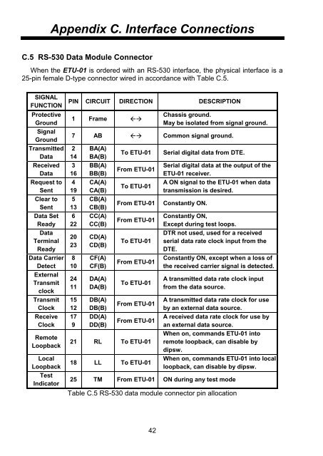
Appendix C. Interface <strong>Co</strong>nnectionsC.5 RS-530 Data Module <strong>Co</strong>nnectorWhen the <strong>ETU</strong>-<strong>01</strong> is ordered with an RS-530 interface, the physical interface is a25-pin female D-type connector wired in accordance with Table C.5.SIGNALFUNCTIONProtectiveGroundSignalGroundTransmittedDataReceivedDataRequest toSentClear toSentData SetReadyDataTerminalReadyData CarrierDetectExternalTransmitclockTransmitClockReceiveClockRemoteLoopbackLocalLoopbackTestIndicatorPIN CIRCUIT DIRECTION DESCRIPTION1 Frame Chassis ground.May be isolated from signal ground.7 AB <strong>Co</strong>mmon signal ground.214316419513622202381024111512179BA(A)BA(B)BB(A)BB(B)CA(A)CA(B)CB(A)CB(B)CC(A)CC(B)CD(A)CD(B)CF(A)CF(B)DA(A)DA(B)DB(A)DB(B)DD(A)DD(B)To <strong>ETU</strong>-<strong>01</strong>From <strong>ETU</strong>-<strong>01</strong>To <strong>ETU</strong>-<strong>01</strong>From <strong>ETU</strong>-<strong>01</strong>From <strong>ETU</strong>-<strong>01</strong>To <strong>ETU</strong>-<strong>01</strong>From <strong>ETU</strong>-<strong>01</strong>To <strong>ETU</strong>-<strong>01</strong>From <strong>ETU</strong>-<strong>01</strong>From <strong>ETU</strong>-<strong>01</strong>21 RL To <strong>ETU</strong>-<strong>01</strong>18 LL To <strong>ETU</strong>-<strong>01</strong>Serial digital data from DTE.Serial digital data at the output of the<strong>ETU</strong>-<strong>01</strong> receiver.A ON signal to the <strong>ETU</strong>-<strong>01</strong> when datatransmission is desired.<strong>Co</strong>nstantly ON.<strong>Co</strong>nstantly ON,Except during test loops.DTR not used, used for a receivedserial data rate clock input from theDTE.<strong>Co</strong>nstantly ON, except when a loss ofthe received carrier signal is detected.A transmitted data rate clock inputfrom the data source.A transmitted data rate clock for useby an external data source.A received data rate clock for use byan external data source.When on, commands <strong>ETU</strong>-<strong>01</strong> intoremote loopback, can disable bydipsw.When on, commands <strong>ETU</strong>-<strong>01</strong> into localloopback, can disable by dipsw.25 TM From <strong>ETU</strong>-<strong>01</strong> ON during any test modeTable C.5 RS-530 data module connector pin allocation42