deliverable d1.4 small prototypes of green tram tracks ... - urban track
deliverable d1.4 small prototypes of green tram tracks ... - urban track
deliverable d1.4 small prototypes of green tram tracks ... - urban track

Create successful ePaper yourself
Turn your PDF publications into a flip-book with our unique Google optimized e-Paper software.
D0104_ASP_CDM_M24.doc<br />
TIP5-CT-2006-031312 Page 1 <strong>of</strong> 27<br />
URBAN TRACK Issued: 29/8/2008<br />
Quality checked and approved by project co-ordinator André Van Leuven<br />
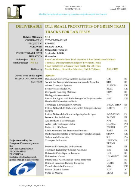
DELIVERABLE D1.4 SMALL PROTOTYPES OF GREEN TRAM<br />
TRACKS FOR LAB TESTS<br />
Related Milestone M1.2<br />
CONTRACT N° TIP5-CT-2006-031312<br />
PROJECT N° FP6-31312<br />
ACRONYM URBAN TRACK<br />
TITLE Urban Rail Transport<br />
PROJECT START DATE September 1, 2006<br />
DURATION 48 months<br />
Subproject SP 1 Low Cost Modular New Track Systems & Fast Installation Methods<br />
Work Package WP 1.2 Technical Developments: Design <strong>of</strong> Ecological Tracks<br />
Small Prototypes <strong>of</strong> Green Tram Tracks for Lab Tests<br />
Written by Martin Richter, Hendrikje Schreiter, Didrik Thijssen ASP, CDM<br />
Date <strong>of</strong> issue <strong>of</strong> this report 29/8/2008<br />
PROJECT CO-ORDINATOR Dynamics, Structures & Systems International D2S BE<br />
PARTNERS Société des Transports Intercommunaux de Bruxelles STIB BE<br />
Alstom Transport Systems ALSTOM FR<br />
Project funded by the<br />
European Community under<br />
the<br />
SIXTH FRAMEWORK<br />
PROGRAMME<br />
PRIORITY 6<br />
Sustainable development,<br />
Bremen Strassenbahn AG BSAG DE<br />
Composite Damping Materials CDM BE<br />
Die Ingenieurswerkstatt DI DE<br />
Institut für Agrar- und Stadtökologische Projekte an der<br />
Humboldt Universität zu Berlin<br />
ASP DE<br />
Tecnologia e Investigacion Ferriaria INECO-TIFSA ES<br />
Institut National de Recherche sur les Transports & leur<br />
Sécurité<br />
INRETS FR<br />
Institut National des Sciences Appliquées de Lyon INSA-CNRS FR<br />
Ferrocarriles Andaluces FA-DGT ES<br />
Alfa Products & Technologies APT BE<br />
Autre Porte Technique Global GLOBAL PH<br />
Politecnico di Milano POLIMI IT<br />
Régie Autonome des Transports Parisiens RATP FR<br />
Studiengesellschaft für Unterirdische Verkehrsanlagen STUVA DE<br />
Stellenbosch University SU ZA<br />
Transport for London LONDON<br />
TRAMS<br />
UK<br />
Ferrocarril Metropolita de Barcelona TMB ES<br />
Transport Technology Consult Karlsruhe TTK DE<br />
Université Catholique de Louvain UCL BE<br />
Universiteit Hasselt UHASSELT BE<br />
global change & ecosystems International Association <strong>of</strong> Public Transport UITP BE<br />
Union <strong>of</strong> European Railway Industries UNIFE BE<br />
Verkehrsbetriebe Karlsruhe VBK DE<br />
Fritsch Chiari & Partner FCP AT<br />
Metro de Madrid MDM ES
D0104_ASP_CDM_M24.doc<br />
TIP5-CT-2006-031312 Page 2 <strong>of</strong> 27<br />
URBAN TRACK Issued: 29/8/2008<br />
Quality checked and approved by project co-ordinator André Van Leuven<br />
T A B L E O F C O N T E N T S<br />
0. Executive Summary ..........................................................................................................................3<br />
0.1. Objective <strong>of</strong> the Deliverable..............................................................................................................3<br />
0.2. Strategy Used and/or a Description <strong>of</strong> the Methods (Techniques) Used with the Justification<br />
There<strong>of</strong>................................................................................................................................................3<br />
0.3. Background Info Available and the Innovative Elements Which Were Developed .....................3<br />
0.4. Problems Encountered ......................................................................................................................4<br />
0.5. Partners Involved and Their Contribution.......................................................................................4<br />
0.6. Conclusions........................................................................................................................................5<br />
1. Introduction.......................................................................................................................................6<br />
2. Description <strong>of</strong> Prototypes with Sedum Vegetation ......................................................................7<br />
2.1. Structure <strong>of</strong> Test Bodies.....................................................................................................................8<br />
2.1.1 Grass Paver .....................................................................................................................................9<br />
2.1.2 Substrate..........................................................................................................................................9<br />
2.1.3 Anti Root Foil..................................................................................................................................9<br />
2.1.4 Drainage/Base Layer....................................................................................................................10<br />
2.1.5 Special Absorber ...........................................................................................................................11<br />
2.2. Prototype 1 (Special Absorber – Drain Concrete)..........................................................................14<br />
2.3. Prototype 2 (Special Absorber – Rubber Mat) ...............................................................................16<br />
2.4. Prototype 3 (Grass Paver)................................................................................................................17<br />
3. Description <strong>of</strong> Prototypes with Artificial Grass..........................................................................19<br />
3.1. Artificial grass..................................................................................................................................19<br />
3.2. Track design.....................................................................................................................................20<br />
3.3. Artificial <strong>green</strong> <strong>track</strong> <strong>prototypes</strong>.....................................................................................................21<br />
4. Tests and Action Performed ..........................................................................................................25<br />
4.1. Pre-cultivation..................................................................................................................................25<br />
4.2. Fatigue Tests ....................................................................................................................................25<br />
5. Tests and Action Planned ..............................................................................................................26<br />
5.1. Noise Measurements at Brussels Test Site .....................................................................................26<br />
6. Problems Encountered ...................................................................................................................27
0. EXECUTIVE SUMMARY<br />
D0104_ASP_CDM_M24.doc<br />
TIP5-CT-2006-031312 Page 3 <strong>of</strong> 27<br />
URBAN TRACK Issued: 29/8/2008<br />
Quality checked and approved by project co-ordinator André Van Leuven<br />
0.1. OBJECTIVE OF THE DELIVERABLE<br />
This <strong>deliverable</strong> describes <strong>prototypes</strong> <strong>of</strong> developed <strong>green</strong> <strong>tram</strong> <strong>track</strong> designs which meet the<br />
requirements <strong>of</strong> technical standards and come up with solutions to specific problems. Within<br />
the Urban Track project a sustainable, low maintenance, improved noise absorbing, well water<br />
balanced <strong>green</strong> <strong>track</strong> with regard to the particular local climate and required technical<br />
standards (stray current) has to be developed, which allows occasional use <strong>of</strong> emergency<br />
vehicles. Track design, materials and plant varieties influence those parameters, thus were<br />
developed or chosen according to their particular suitability, respectively.<br />
0.2. STRATEGY USED AND/OR A DESCRIPTION OF THE METHODS<br />
(TECHNIQUES) USED WITH THE JUSTIFICATION THEREOF<br />
The strategy is to develop a vegetation system and <strong>track</strong> design, according to the problems and<br />
requirements <strong>of</strong> <strong>green</strong> <strong>tram</strong> <strong><strong>track</strong>s</strong> and conducting tests on materials to be considered. Review<br />
and specific tests on applicable materials for <strong>green</strong> <strong>tram</strong> <strong><strong>track</strong>s</strong> regarding their characteristics to<br />
our SWP- objectives were done and have influenced the material choice. Certain parameters <strong>of</strong><br />
the developed solutions were further modified and will underlie additional developments<br />
based on the results gained during further tests and the first practical test at Brussels (SP3).<br />
0.3. BACKGROUND INFO AVAILABLE AND THE INNOVATIVE ELEMENTS<br />
WHICH WERE DEVELOPED<br />
Background info available:<br />
- Specifications provided by IASP<br />
- Specifications provided by STIB<br />
- Specifications provided by CDM<br />
Innovative elements:<br />
- low maintenance drivable solution using Sedum.<br />
- with Sedum pre-cultivated grass paver.<br />
- using a better noise absorbing material as rail shoulder than conventional concrete or the<br />
known rubber elements (e.g. from Sedra or Kraiburg).
D0104_ASP_CDM_M24.doc<br />
TIP5-CT-2006-031312 Page 4 <strong>of</strong> 27<br />
URBAN TRACK Issued: 29/8/2008<br />
Quality checked and approved by project co-ordinator André Van Leuven<br />
- preventing excessive weed growth at the connection <strong>of</strong> the root foils and the sides <strong>of</strong> the<br />
<strong>track</strong> by means <strong>of</strong> inserting the foil end into the concrete board separating the <strong>track</strong> from<br />
the road and into the longitudinal concrete beam in which the rail is embedded.<br />
- improved quality <strong>of</strong> last generation artificial grass.<br />
- limiting maintenance and good drivable solution using artificial grass.<br />
0.4. PROBLEMS ENCOUNTERED<br />
IASP<br />
During the fatigue test the drainage material had to be changed, as both split and gravel were to<br />
similar in grit size and therefore not compressible enough. This caused loss <strong>of</strong> time, with the<br />
effect that firstly only 2 <strong>prototypes</strong> (version 1) could be tested properly and secondly that this<br />
test only comprised 4,600 wheel crossings. Consequently not all test questions have been<br />
answered.<br />
No suitable grass paver for our pre-cultivation purposes is available on the market. Producers<br />
are not interested in developing a new design at the moment, because <strong>of</strong> high costs for a new<br />
mold.<br />
Moreover, an industrial bonding <strong>of</strong> the foil to the sides <strong>of</strong> the <strong>track</strong> is needed. It is being tested<br />
at the moment if a pre-cultivation without fleece was feasible.<br />
CDM<br />
It was difficult to simulate the real situation <strong>of</strong> artificial grass at the test circuit <strong>of</strong> STUVA. No<br />
real problems have been encountered.<br />
0.5. PARTNERS INVOLVED AND THEIR CONTRIBUTION<br />
CDM basic <strong>track</strong> design<br />
design <strong>of</strong> rail jacket and concrete beam<br />
ongoing development <strong>of</strong> combination <strong>of</strong> artificial and real vegetation<br />
shared tests (e.g. noise absorption, fatigue test, Brussels test site)<br />
STIB (WP 3.2) operator <strong>of</strong> Brussels test site
D0104_ASP_CDM_M24.doc<br />
TIP5-CT-2006-031312 Page 5 <strong>of</strong> 27<br />
URBAN TRACK Issued: 29/8/2008<br />
Quality checked and approved by project co-ordinator André Van Leuven<br />
have specific demands on <strong>track</strong> design<br />
STUVA conduct fatigue test<br />
IASP Development <strong>of</strong> vegetation system with real plants<br />
0.6. CONCLUSIONS<br />
This <strong>deliverable</strong> provides input to SP1 and SP3, for those applications were <strong>green</strong> <strong>tram</strong> <strong><strong>track</strong>s</strong><br />
are planned to be used.<br />
It also has relations with SP4 because <strong>of</strong> the life cycle cost calculations that have to be<br />
performed.
1. INTRODUCTION<br />
D0104_ASP_CDM_M24.doc<br />
TIP5-CT-2006-031312 Page 6 <strong>of</strong> 27<br />
URBAN TRACK Issued: 29/8/2008<br />
Quality checked and approved by project co-ordinator André Van Leuven<br />
This <strong>deliverable</strong> describes <strong>prototypes</strong> <strong>of</strong> developed <strong>green</strong> <strong>tram</strong> <strong>track</strong> designs which meet the<br />
requirements <strong>of</strong> technical standards and come up with solutions to specific problems: Within<br />
the Urban Track project a sustainable, low maintenance, improved noise absorbing, well water<br />
balanced <strong>green</strong> <strong>track</strong> with regard to the particular local climate and required technical<br />
standards (stray current) has been developed, which allows occasional use <strong>of</strong> emergency<br />
vehicles. Track design, materials, plant and artificial grass varieties influence those parameters.<br />
They had to be developed or chosen according to their particular suitability.<br />
To ensure the passage <strong>of</strong> emergency vehicles the developed <strong>green</strong> <strong><strong>track</strong>s</strong> must be able to carry<br />
the load <strong>of</strong> these vehicles. Therefore a fatigue test at STUVA was carried out. For the detailed<br />
description <strong>of</strong> the test equipment see D2.11 prepeared by STUVA.
D0104_ASP_CDM_M24.doc<br />
TIP5-CT-2006-031312 Page 7 <strong>of</strong> 27<br />
URBAN TRACK Issued: 29/8/2008<br />
Quality checked and approved by project co-ordinator André Van Leuven<br />
2. DESCRIPTION OF PROTOTYPES WITH SEDUM<br />
VEGETATION<br />
Three different <strong>green</strong> <strong>tram</strong> <strong>track</strong> <strong>prototypes</strong> have been developed so far. They are going to be<br />
tested and optimised during SP 3.2. They represent three <strong>track</strong> design versions which are going<br />
to be put into practice in a test zone in Brussels, each. All three <strong>of</strong> them aim to reduce as much<br />
reverberant <strong>track</strong> surface as possible to mitigate noise reflection. These <strong>prototypes</strong> are built for<br />
fatigue testing at the test site <strong>of</strong> the project partner STUVA. The test conditions determine the<br />
outer dimensions <strong>of</strong> the test bodies. The three design versions implement an extensive, thin<br />
layered vegetation system which applies Sedum-moss vegetation. The dimensions <strong>of</strong> this<br />
system result from plant needs and low maintenance reasons, since the drought tolerant Sedum<br />
only needs fertilizer once a year and survives dry periods better than any other plant or weed<br />
which might start to grow in the <strong>track</strong>. A more detailed explanation why this vegetation system<br />
was chosen is given in the last progress report for D1.3 (2007). The single elements are described<br />
more detailed in this year’s final <strong>deliverable</strong> D1.3 (2008). The dimensions <strong>of</strong> the rail parts (rail,<br />
rubber jacket, concrete foot) are supplied by CDM (see D1.4 from CDM). Design and<br />
dimensions <strong>of</strong> the <strong>prototypes</strong> are shown in the figures below.<br />
For the test bodies no plants are used since this does not give additional information.<br />
Steel frame, rail and rail encapsulation <strong>of</strong> the 6 <strong>prototypes</strong> were built by CDM and transported<br />
to STUVA where the <strong>prototypes</strong> were tested for their fatigue stability. Mr. RIFFEL from<br />
HEIDELBERGCEMENT installed drain concrete in 2 <strong>prototypes</strong> at STUVA test site, which had to<br />
dry for 28 days. IASP did the finish by installing the vegetation system: drainage layer, foil,<br />
grass paver, Xeroterr I (substrate).<br />
The 3 versions were repeated twice (6 test bodies), each repetition filled with either gravel or<br />
split.
D0104_ASP_CDM_M24.doc<br />
TIP5-CT-2006-031312 Page 8 <strong>of</strong> 27<br />
URBAN TRACK Issued: 29/8/2008<br />
Quality checked and approved by project co-ordinator André Van Leuven<br />
2.1. STRUCTURE OF TEST BODIES<br />
Figure 1: Overview <strong>of</strong> the vegetation system / <strong>track</strong> design. Left: special noise absorber as hard<br />
shoulder, Right: grass paver up to rubber jacket<br />
Standard structure <strong>of</strong> the test bodies:<br />
Drainage layer /<br />
base layer<br />
� 19.5 cm<br />
Anti root foil � 0.5 mm<br />
� 3 bodies received a split filling (8/16),<br />
� 3 a gravel filling (8/11);<br />
� In later tests the two bodies <strong>of</strong> version 1 received a mixture <strong>of</strong> mineral<br />
materials (grit size 0/32)<br />
� PE<br />
Grass paver � 5 cm thick<br />
Area next to rail<br />
(hard shoulder)<br />
� Fleece (0.2-0.5 mm) glued to the bottom<br />
� Filled with 4 cm Xeroterr I (substrate)<br />
� Consisted either <strong>of</strong> drain concrete (version 1), rubber absorber<br />
(version 2) or grass paver (version 3)
2.1.1 Grass Paver<br />
D0104_ASP_CDM_M24.doc<br />
TIP5-CT-2006-031312 Page 9 <strong>of</strong> 27<br />
URBAN TRACK Issued: 29/8/2008<br />
Quality checked and approved by project co-ordinator André Van Leuven<br />
The top <strong>of</strong> the prototype consist <strong>of</strong> grass pavers (System: SCHWAB), which have a thickness <strong>of</strong><br />
51 mm.<br />
Figure 2: Grass paver, System SCHWAB Figure 3: Grass paver prepared for pre-cultivation by gluing<br />
fleece to the bottom, to prevent soil from falling<br />
out during transport<br />
These pavers are assembled from single elements (size: 580 x 380 x 51 mm). Since the vegetation<br />
is going to be pre-cultivated in these grass pavers and transported to the installation site<br />
afterwards, a fleece (approx. 0.2-0.5 mm) needs to seal the bottom part <strong>of</strong> the grass pavers to<br />
prevent the substrate from falling out during transport. This fleece is glued to the grass paver<br />
and is permeable to water.<br />
2.1.2 Substrate<br />
The substrate level within the grass paver is 40-45 mm. This ensures plant re-growth in case <strong>of</strong><br />
plant damaged by car tires. The substrate used is going to keep a stable structure so that the<br />
level filled in the grass paver will be obtained.<br />
2.1.3 Anti Root Foil<br />
Below the fleece material, an anti-root foil, made <strong>of</strong> PE with a thickness <strong>of</strong> 0.5 mm, is installed.<br />
To ensure a good drainage during heavy rain the foil is perforated (diameter: ca. 1 mm) every<br />
running meter. To keep the foil closely connected to the sides it was thought to be incorporated<br />
into the rubber jacket during production process, 51 mm below the surface, about 30 mm deep<br />
but could not be realized as such. This fixation is necessary to ensure position stability <strong>of</strong> the foil<br />
and to prevent weed growth by restricting the substrate level to 4 cm thickness.<br />
For the <strong>prototypes</strong> <strong>of</strong> version 1 the anti root foil could not be clamped between the concrete<br />
types as planned, since Mr. RIFFEL from HeidelbergCement predicted problems with the bond
D0104_ASP_CDM_M24.doc<br />
TIP5-CT-2006-031312 Page 10 <strong>of</strong> 27<br />
URBAN TRACK Issued: 29/8/2008<br />
Quality checked and approved by project co-ordinator André Van Leuven<br />
<strong>of</strong> the concrete otherwise. Therefore it was bent down in a 90° angle along the concrete beam<br />
and held by the drainage, more or less.<br />
For the <strong>prototypes</strong> <strong>of</strong> version 2 (rubber absorber) the foil was glued to rubber absorber and<br />
concrete beam by means <strong>of</strong> Sikaflex (SIKA Deutschland GmbH) (see Figure 1, left side). The<br />
bonding was not very tight and resulted in bad bonding <strong>of</strong> the rubber absorber to the concrete.<br />
During the first fatigue tests the grass paver gave way to the load applied so the rubber<br />
absorber received the full load <strong>of</strong> the tyre on one side and came <strong>of</strong>f.<br />
For the <strong>prototypes</strong> <strong>of</strong> version 3 (grass paver) a slot was cut into the rubber jacket, surrounding<br />
the rail. The foil was pushed into the slot with difficulties and though glued did not clung very<br />
well.<br />
2.1.4 Drainage/Base Layer<br />
For the first fatigue test run the drainage layer <strong>of</strong> the <strong>prototypes</strong> was made <strong>of</strong> gravel with grain<br />
sizes 8/11 mm (version 1-3) as well as <strong>of</strong> split (8/16), (version 1-3). A more stable behaviour <strong>of</strong><br />
split compared to gravel was expected, due to its shape. This layer is usually constructed as fine<br />
plane with a 1% slope towards the middle <strong>of</strong> the <strong>track</strong>.<br />
Figure 4: Split (8/16) Figure 5: Gravel (8/11)<br />
Since those materials were not stable enough during the test (neither split nor gravel) they were<br />
replaced by a mixture <strong>of</strong> mineral materials (0/32) in both <strong>prototypes</strong> <strong>of</strong> version 1 (drain<br />
concrete). This material was far more compressible and therefore was stable enough to carry the<br />
load <strong>of</strong> emergency vehicles (wheel load during fatigue test: 3.5 t).
Figure 6: Mineral mixture (0/32)<br />
2.1.5 Special Absorber<br />
Drain concrete (TioCem)<br />
D0104_ASP_CDM_M24.doc<br />
TIP5-CT-2006-031312 Page 11 <strong>of</strong> 27<br />
URBAN TRACK Issued: 29/8/2008<br />
Quality checked and approved by project co-ordinator André Van Leuven<br />
A new material, drain concrete “TiOCem” developed by HeidelbergCement has been tested<br />
and can be implemented as special absorber.<br />
Figure 7: Drain concrete (HEIDELBERGCEMENT)<br />
Figure 8: Conversion <strong>of</strong> NOx to NO3 - by titanium dioxide and UV-radiation (HEIDELBERGCEMENT)
D0104_ASP_CDM_M24.doc<br />
TIP5-CT-2006-031312 Page 12 <strong>of</strong> 27<br />
URBAN TRACK Issued: 29/8/2008<br />
Quality checked and approved by project co-ordinator André Van Leuven<br />
Drain concrete is an open porous concrete which possesses a good noise absorption, with up to<br />
5 dB(A) (RIFFEL, HEIDELBERGCEMENT), is drainable, therefore increases evaporation and<br />
converts NOx to NO3 - by incorporated titanium dioxide.<br />
Figure 9: Typical composition and quality requirements <strong>of</strong> drain concrete<br />
Concrete strength class C 20/25<br />
Aggregate Fine flint 5/8 mm 1,450 – 1,500 kg/m³<br />
Cement CEM I 32,5 R 300 - 350 kg/m³<br />
Water (Fresh water) 50 - 55 kg/m³<br />
Synthetics dispersion<br />
20 % <strong>of</strong> weight (10 %<br />
solids)<br />
60 - 70 kg/m³<br />
w/c-factor 0.24 – 0.26 (effective)<br />
Consistency V 1.30 – 1.34 (C1)<br />
Void content P � 20 Vol.-%<br />
Compression strenght fck* � 25 N/mm²<br />
Bending tensile strenght fct* � 3.5 N/mm²<br />
Splitting tensile strenght fct* � 2.7 N/mm²<br />
Adhesive tensile strenght fct � 1.5 N/mm 2<br />
Static modulus <strong>of</strong><br />
elasticity<br />
�B<br />
16,000 – 18,000 N/mm²
Porous rubber (CDM 46)<br />
D0104_ASP_CDM_M24.doc<br />
TIP5-CT-2006-031312 Page 13 <strong>of</strong> 27<br />
URBAN TRACK Issued: 29/8/2008<br />
Quality checked and approved by project co-ordinator André Van Leuven<br />
The CDM porous rubber mat 46 is made <strong>of</strong> rubber granules <strong>of</strong> shredded tires which are bonded with a<br />
polyurethane binder under high pressure. During impedance measurements in the previous year this<br />
mat showed the best noise absorption <strong>of</strong> the tested materials (see progress report D1.3).<br />
Figure 10: Porous rubber mat (CDM 46)<br />
Figure 11: Typical composition and quality requirements <strong>of</strong> CDM 46<br />
Prescription Unit CDM-46<br />
Material Resin bonded rubber<br />
Colour black<br />
Density - ASTM-D297 kg/m³ 990<br />
Shore hardness -ASTM-D2240 °A 50-60<br />
Tensile strength – ASTM-F152 MPa > 0.5<br />
Elongation at break - ISO-37 % > 40<br />
Compressability at 2.8 MPa – ASTM-F36 % 30-50<br />
Recovery at 2.8 MPa - ASTM-F36 % > 90<br />
Compression set 50%/23°C/70h – DIN53572 % < 10
D0104_ASP_CDM_M24.doc<br />
TIP5-CT-2006-031312 Page 14 <strong>of</strong> 27<br />
URBAN TRACK Issued: 29/8/2008<br />
Quality checked and approved by project co-ordinator André Van Leuven<br />
2.2. PROTOTYPE 1 (SPECIAL ABSORBER – DRAIN CONCRETE)<br />
In Prototype 1a special noise absorbing drain concrete was implemented next to the rubber<br />
jacket which encapsulates the rail. The drain concrete replaces the upper part <strong>of</strong> the in Brussels<br />
usually used concrete beam, surrounding the rubber jacket. The dimensions <strong>of</strong> the drain<br />
concrete are 51 mm (thick) x 90 mm (wide).<br />
Figure 12: Prototype version 1, special noise absorbing and NOx converting TioCem drain concrete<br />
next to rail
D0104_ASP_CDM_M24.doc<br />
TIP5-CT-2006-031312 Page 15 <strong>of</strong> 27<br />
URBAN TRACK Issued: 29/8/2008<br />
Quality checked and approved by project co-ordinator André Van Leuven<br />
Figure 13: Installation <strong>of</strong> TioCem drain concrete<br />
Figure 14: 6 empty test bodies for fatigue test,<br />
IASP<br />
Figure 16: Anti root foil (version 2)<br />
Figure 15: Drainage layer filled in (version 3)<br />
Figure 17: Fitting <strong>of</strong> grass paver to test body shape<br />
(version 3)
D0104_ASP_CDM_M24.doc<br />
TIP5-CT-2006-031312 Page 16 <strong>of</strong> 27<br />
URBAN TRACK Issued: 29/8/2008<br />
Quality checked and approved by project co-ordinator André Van Leuven<br />
Figure 18: Drain concrete prototype, ready for testing<br />
2.3. PROTOTYPE 2 (SPECIAL ABSORBER – RUBBER MAT)<br />
Prototype 2 is a variation <strong>of</strong> Prototype 1. The difference is an additional material (special noise<br />
absorber) implemented next to the rail on top <strong>of</strong> the concrete which can be used to drive on.<br />
This accommodates operators which prefer a firm shoulder next to the rail. For the prototype<br />
the rubber mat “CDM 46” is used. This material can be prefabricated and installed with lower<br />
efforts than the slightly more noise absorbing drain asphalt. The dimensions <strong>of</strong> the rubber mat<br />
are 51 mm (thick) x 90 mm (wide).<br />
Figure 19: Prototype version 2, noise absorbing porous rubber mat (CDM 46) as hard shoulder
D0104_ASP_CDM_M24.doc<br />
TIP5-CT-2006-031312 Page 17 <strong>of</strong> 27<br />
URBAN TRACK Issued: 29/8/2008<br />
Quality checked and approved by project co-ordinator André Van Leuven<br />
For the <strong>prototypes</strong> in version 2 a slot was cut into the rubber jacket, surrounding the rail. The<br />
foil was pushed into the slot with difficulties. The 0.5 mm anti root foil was glued between<br />
absorber and concrete by means <strong>of</strong> Sikaflex glue. But as already predicted the bonding was not<br />
satisfactory.<br />
Figure 20: Rubber absorber test body, ready for testing<br />
2.4. PROTOTYPE 3 (GRASS PAVER)<br />
In version 3 grass paver replaced the upper 5 cm thick layer <strong>of</strong> the concrete beam and reached<br />
up to the rubber jacket. The foil was put, with difficulties, into a slot within the rubber jacket.<br />
The rest <strong>of</strong> the foil was glued to the concrete beam by means <strong>of</strong> Sikaflex. The bonding was not<br />
good enough though, so the foil already came <strong>of</strong>f during installation <strong>of</strong> the vegetation system.<br />
Figure 21: Prototype version 3, grass paver up to rubber jacket, surrounding the rail
D0104_ASP_CDM_M24.doc<br />
TIP5-CT-2006-031312 Page 18 <strong>of</strong> 27<br />
URBAN TRACK Issued: 29/8/2008<br />
Quality checked and approved by project co-ordinator André Van Leuven<br />
Figure 22: Test body with grass paver up to rubber jacket, ready for testing
D0104_ASP_CDM_M24.doc<br />
TIP5-CT-2006-031312 Page 19 <strong>of</strong> 27<br />
URBAN TRACK Issued: 29/8/2008<br />
Quality checked and approved by project co-ordinator André Van Leuven<br />
3. DESCRIPTION OF PROTOTYPES WITH ARTIFICIAL GRASS<br />
3.1. ARTIFICIAL GRASS<br />
Artificial grass finishing has the following advantages :<br />
• possibility to install on existing <strong>track</strong><br />
• low grass maintenance<br />
• fast and easy installation<br />
• permanently <strong>green</strong><br />
• low life cycle cost compared to natural grass<br />
• good noise absorption<br />
• improved quality <strong>of</strong> last generation artificial grass<br />
The technical specification <strong>of</strong> the high grade artificial grass CDM used for the <strong>prototypes</strong> are :<br />
Fibres 100% polyamide, 14.000 dtex<br />
Number <strong>of</strong> knots/m² 17 640/m² +/- 10%<br />
Number <strong>of</strong> filaments/m² 400 000/m² +/- 10%<br />
Strength <strong>of</strong> fibres 315N (Pr EN 13864)<br />
Recuperation <strong>of</strong> fibre after bending 83,5° after 60 min.<br />
Height <strong>of</strong> fibres 38 mm +/- 5%<br />
Shrinkage height 15 min. at 150°C 2 mm<br />
100% mon<strong>of</strong>ilament (straight and curled)<br />
Withdrawal force fibres 47N (ISO 4919, BS 5229)<br />
Fixation <strong>of</strong> fibres Latex rubber<br />
Total weight 3 364 gr/m² +/- 5%<br />
Filling No filling necessary<br />
Colour Green (4 ranges <strong>of</strong> colours)<br />
Colour fastness Scale 7 (DIN 54004)<br />
UV-Stability > 6000 hours (DIN 53387)
D0104_ASP_CDM_M24.doc<br />
TIP5-CT-2006-031312 Page 20 <strong>of</strong> 27<br />
URBAN TRACK Issued: 29/8/2008<br />
Quality checked and approved by project co-ordinator André Van Leuven<br />
Chlor resistance 4-5 (DIN 54019)<br />
Resistance to sea water 4-5 (DIN 54007)<br />
Water permeability 6e4 m/sec<br />
Inflammability Class 1 (DIN 51960)<br />
Toxic fume emission None ITC = 33 (NF X 70-100)<br />
Acoustic absorption coefficient 0,54 at 2037 Hz (tube <strong>of</strong> Kundt test,<br />
ISO 10534-1)<br />
For the gluing <strong>of</strong> the grass a Polyurethane based adherent was used. Figure 23 shows the very<br />
realistic looks <strong>of</strong> the artificial grass.<br />
Figure 23: Looks <strong>of</strong> a high grade artificial grass sample<br />
3.2. TRACK DESIGN<br />
The global <strong>track</strong> design which will be used for the validation <strong>track</strong> in Brussels (SP 3.2) is shown<br />
in figure 26. The jacketed rails are embedded in the concrete slab which is covered with the<br />
artificial grass layer. Rain water drainage is guaranteed via sideward inclination <strong>of</strong> the slab<br />
surfaces.
D0104_ASP_CDM_M24.doc<br />
TIP5-CT-2006-031312 Page 21 <strong>of</strong> 27<br />
URBAN TRACK Issued: 29/8/2008<br />
Quality checked and approved by project co-ordinator André Van Leuven<br />
Figure 24: Cross section <strong>of</strong> <strong>track</strong> construction with artificial grass surface layer<br />
3.3. ARTIFICIAL GREEN TRACK PROTOTYPES<br />
Four test blocks with two different types <strong>of</strong> artificial grass finish (high grade with a very<br />
realistic look and lower grade grass) and two different adherence techniques (glued on concrete<br />
slab and integrated into the fresh concrete) were made for testing on the STUVA ring. When<br />
putting the artificial grass layer directly in the fresh concrete, metal sheets were placed along<br />
the sides <strong>of</strong> the jacket to protect them against mechanical deterioration by the occasional road<br />
traffic.<br />
Figure 24 shows the metal works construction and glueing <strong>of</strong> grass on a test block which will fit<br />
in the STUVA test ring set up for prototype testing.<br />
Figure 24: Test block construction and grass application process
D0104_ASP_CDM_M24.doc<br />
TIP5-CT-2006-031312 Page 22 <strong>of</strong> 27<br />
URBAN TRACK Issued: 29/8/2008<br />
Quality checked and approved by project co-ordinator André Van Leuven<br />
Version 1: Artificial grass -5mm top <strong>of</strong> rail (TOR) - rail perpendicular wheel<br />
2 types <strong>of</strong> artificial grass were used for this test body: low density and high density. One rail has<br />
metallic plates to protect the jacket, the other one has not. This way the difference can be<br />
compared after the test.<br />
Figure 25 Version 1<br />
Version 2: Artificial grass -5mm TOR – rail longitudinal wheel<br />
The rail is placed in the same direction as the direction <strong>of</strong> the wheel <strong>of</strong> the test circuit. Metal<br />
plates are used to protect the jackets. Only high density grass is tested.
Figure 26 Version 2<br />
D0104_ASP_CDM_M24.doc<br />
TIP5-CT-2006-031312 Page 23 <strong>of</strong> 27<br />
URBAN TRACK Issued: 29/8/2008<br />
Quality checked and approved by project co-ordinator André Van Leuven<br />
Version 3: Artificial grass glued TOR - rail perpendicular wheel<br />
2 types <strong>of</strong> artificial grass were used for this test body: low density and high density. No metallic<br />
plates are used.<br />
Figure 27 Version 3<br />
Version 4: Artificial grass -5mm TOR – rail longitudinal wheel<br />
The rail is placed in the same direction as the direction <strong>of</strong> the wheel <strong>of</strong> the test circuit. No metal<br />
plates are used. Only high density grass is tested.
Figure 28 Version 4<br />
D0104_ASP_CDM_M24.doc<br />
TIP5-CT-2006-031312 Page 24 <strong>of</strong> 27<br />
URBAN TRACK Issued: 29/8/2008<br />
Quality checked and approved by project co-ordinator André Van Leuven<br />
The four blocks were finaly shipped to STUVA for wear testing.<br />
Figure 29 Prototypes before transport to STUVA
D0104_ASP_CDM_M24.doc<br />
TIP5-CT-2006-031312 Page 25 <strong>of</strong> 27<br />
URBAN TRACK Issued: 29/8/2008<br />
Quality checked and approved by project co-ordinator André Van Leuven<br />
4. TESTS AND ACTION PERFORMED<br />
4.1. PRE-CULTIVATION<br />
During the pre-cultivation process <strong>of</strong> Sedum in grass paver several questions <strong>of</strong> practical<br />
realizations appeared and have to be solved. Focus is being laid on an economic production<br />
process to simplify pre-cultivation for further test zones. For further details see D1.3 (2008).<br />
4.2. FATIGUE TESTS<br />
The fatigue test at STUVA in Cologne is supposed to test the interaction <strong>of</strong> the system parts<br />
under the load <strong>of</strong> a lorry wheel. This simulates the use <strong>of</strong> the system by emergency vehicles for<br />
instance over 10 years.<br />
Figure 30: Fatigue test at STUVA<br />
Tested were: the fatigue <strong>of</strong> the whole system and its single components as well as their<br />
interaction. For further details and results see D1.3 (2008).
D0104_ASP_CDM_M24.doc<br />
TIP5-CT-2006-031312 Page 26 <strong>of</strong> 27<br />
URBAN TRACK Issued: 29/8/2008<br />
Quality checked and approved by project co-ordinator André Van Leuven<br />
5. TESTS AND ACTION PLANNED<br />
5.1. NOISE MEASUREMENTS AT BRUSSELS TEST SITE<br />
At Brussels test site different <strong>track</strong> designs are going to be tested for noise absorption behaviour<br />
at 4 different zones. Three Sedum versions and one artificial grass version are planned to be<br />
installed and tested. Placing these zones right next to each other a comparison <strong>of</strong> the noise<br />
absorption behaviour at probably exactly the same conditions can be made.
D0104_ASP_CDM_M24.doc<br />
TIP5-CT-2006-031312 Page 27 <strong>of</strong> 27<br />
URBAN TRACK Issued: 29/8/2008<br />
Quality checked and approved by project co-ordinator André Van Leuven<br />
6. PROBLEMS ENCOUNTERED<br />
IASP<br />
During the fatigue test the drainage material had to be changed, as both split and gravel were to<br />
similar in grit size and therefore not compressible enough. This caused loss <strong>of</strong> time, with the<br />
effect that firstly only 2 <strong>prototypes</strong> (version 1) were being tested properly and secondly that this<br />
test only comprised 4600 wheel crossings. Consequently not all test questions have been<br />
answered.<br />
No suitable grass paver for our pre-cultivation purposes is on the market. Producers are not<br />
interested in developing a new design at the moment, because <strong>of</strong> high costs for a new mould.<br />
Moreover, an industrial bonding <strong>of</strong> the foil to the sides <strong>of</strong> the <strong>track</strong> is needed. It is being tested<br />
at the moment if a pre-cultivation without fleece was feasible.<br />
CDM<br />
None.