Linear Positioners Catalog_en-US_revA - Kollmorgen
Linear Positioners Catalog_en-US_revA - Kollmorgen
Linear Positioners Catalog_en-US_revA - Kollmorgen

You also want an ePaper? Increase the reach of your titles
YUMPU automatically turns print PDFs into web optimized ePapers that Google loves.
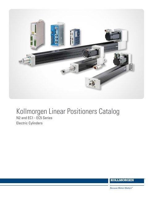
Kollmorg<strong>en</strong> <strong>Linear</strong> <strong>Positioners</strong> <strong>Catalog</strong>N2 and EC1 - EC5 SeriesElectric Cylinders
Kollmorg<strong>en</strong>.Every solution comes from a realunderstanding of OEM chall<strong>en</strong>ges.The ever-escalating demands of the marketplace mean increased pressureon OEMs at every turn. Time constraints. Demands for better performance.Having to think about the next-g<strong>en</strong>eration machine ev<strong>en</strong> before the curr<strong>en</strong>tone is built. While expectations are <strong>en</strong>ormous, budgets are not. Kollmorg<strong>en</strong>’sinnovative motion solutions and quality products help <strong>en</strong>gineers not onlyovercome these chall<strong>en</strong>ges but also build truly differ<strong>en</strong>tiated machines.Because motion matters, it’s our focus. Motion can distinctly differ<strong>en</strong>tiate amachine and deliver a marketplace advantage by improving it’s performance.This translates to overall increased effici<strong>en</strong>cy on the factory floor. Perfectlydeployed machine motion can make your customer’s floor more reliableand effici<strong>en</strong>t, <strong>en</strong>hance accuracy and improve operator safety. Motion alsorepres<strong>en</strong>ts <strong>en</strong>dless possibilities for innovation. We’ve always understood thispot<strong>en</strong>tial, and have kept motion at our core, rel<strong>en</strong>tlessly developing productsthat offer precision control of speed, accuracy and position in machines thatrely on complex motion.K O L L M O R G E N
K O L L M O R G E N L I N E A R P O S I T I O N E R S C A T A L O GTable of Cont<strong>en</strong>tsElectric Cylinder Servo Systems - Overview 4, 5Electric Cylinder - Features 6, 7Electric Cylinder Specifications - Overview 8N2 Series G<strong>en</strong>eral Specifications 9 - 11EC Series G<strong>en</strong>eral Specifications 12 - 19Performance DataQuick Selection Guide 20Performance Summary 21 - 24Thrust Speed CurvesN2 Series 25, 26EC1 Series 27, 28EC2 Series 29, 30EC3 Series 31 - 33EC4 Series 34 - 36EC5 Series 37 - 40Servo System Curr<strong>en</strong>t Calculation 41Outline Drawings - Electric CylindersN2 Series - Outline Drawings 42 - 47N2 Series - Rod-End Adapters 48EC Series - Outline Drawings 49 - 54EC Series - Rod-End Adapters 55Servo Drive Overview - Selection Guide 70S200 Drive 71 - 73S300 Drive 74, 75Smart Drive Drive/IEC 61131 Control 76 - 79Application Engineering Refer<strong>en</strong>ce 80 - 97Engineering Refer<strong>en</strong>ce 98 - 103Application Worksheet 104 - 107Ordering Information N2 Series 108, 109Ordering Information EC Series 110, 111Ordering Information Servo Drive SystemsS200 Drive 112S300 Drive 113Smart Drive Drive/IEC 61131 Control 114, 115AKM motor options for Electric Cylinders 116Outline Drawings - AKM ServomotorsAKM1x frame 117AKM2x frame 118AKM4x frame 119AKM5x frame 120Options and Accessories - Electric Cylinders 56 - 64AKM Brushless Servo - System SummaryAKM1x Servo Systems 65AKM23 Servo Systems 66AKM42 Servo Systems 67AKM52G Servo Systems 68AKM52L Servo Systems 69www.kollmorg<strong>en</strong>.com3
N2 & EC Series Electric Cylinder Servo SystemsL I N E A R P O S I T I O N E R SN2 with AKM23Kollmorg<strong>en</strong>’sElectric Cylinder Servo Systems provide an unpreced<strong>en</strong>ted level of flexibility.EC2 with AKM23º The N2 and EC Series Electric Cylinders offer an unpreced<strong>en</strong>ted degree of flexibility. This flexibility <strong>en</strong>ables solutionto be optimized for the application requirem<strong>en</strong>ts, reducing system cost and minimizing the electric cylinder size.º The flexible design of the N2 and EC Series simplifies <strong>en</strong>gineering design and system integration by providing anintegrated gearing design of both timing belt and helical gearing.º Integrated AKM brushless servomotor provides a system solution reducing application and <strong>en</strong>gineering requirem<strong>en</strong>tsas well as eliminates mechanical interface and interoperability issues. Stepper motors are also available.Standard Configurable Electric Cylinder Designs:N2 SeriesEC SeriesTransport ScrewIntegratedGearingMounting TypesPrecision ballscrew (2 and 5 [rev/in] pitch)Lead screw (5 and 8 [rev/in] pitch)Timing belt (1.0, 1.5, 2.0:1 ratios)Helical gear (2.5, 3.5, 12.0:1 ratios)Inline (direct coupled)7 Parallel Mounts5 Inline MountsPrecision ballscrew (3 to 32 [mm/rev] lead)Lead screw (4 [mm/rev] lead)Timing belt (1.0, 1.5, 2.0:1 ratios)Helical gear (2.0, 2.5, 4.0, 5.0, 7.0, 10.0:1 ratios, model dep<strong>en</strong>d<strong>en</strong>t)Inline (direct coupled)8 Parallel Mounts5 Inline MountsRod-End Adapters 4 Types (English and Metric) 5 Types (English and Metric)Stroke L<strong>en</strong>gthsStandard stroke (2 to 22.5 in)Custom stroke l<strong>en</strong>gths availableStandard stroke l<strong>en</strong>gthsEC1 50 to 200 mm (7.87 in)EC2 50 to 750 mm (29.5 in)EC3 50 to 1000 mm (39.4 in)EC4 & EC5 50 to 1500 mm (59.1 in)Options and AccessoriesElectric Cylinder accessories and time-prov<strong>en</strong> options have be<strong>en</strong> designed for the industrial <strong>en</strong>vironm<strong>en</strong>t to simplify systemintegration. Options include limit switches, dual rod-<strong>en</strong>d bearings, guide bearing, protective boot, and ext<strong>en</strong>ded temperature rangesjust to name a few. See the option and accessory section on pages 56 - 64 for more details.4K O L L M O R G E N
N2 & EC Series Electric Cylinder Servo SystemsThe Electric Cylinders Servo Systems are offered with three Kollmorg<strong>en</strong> brushless servo drive series to provide system flexibility.Let your application and system requirem<strong>en</strong>ts determine what solution integrates the best.• Single v<strong>en</strong>dor solution for the complete electro-mechanicalsystem <strong>en</strong>sures system interoperability and a single dedicatedworldwide motion-control supplier for support.• The Electric Cylinder Servo Systems are available in drive andcontrol technologies ranging form simple and intuitive positioningdrives to fully programmable IEC 61131 based control systems:• The Electric Cylinder Servo Systems leverage multiple Kollmorg<strong>en</strong>Servo Drive/Controllers and the AKM brushless servomotors forcomplete system flexibility and industry leading servo responseand precision.L I N E A R P O S I T I O N E R SS200 115 / 230 VacCompact DriveHigh-Performance• Base Unit: Analog torque-and-velocity, step and direction, <strong>en</strong>coder following• Network Option Cards (SynqNet, D-Link ® Network for IEC 61131 Control)• Indexer Option Card, Simple Positioning System– 180 motion tasks, increm<strong>en</strong>tal absolute positioning, Jog mode– Simple intuitive Graphical User Interface (GUI), no programming experi<strong>en</strong>ce requiredS300 115 / 230 / 400 / 460 VacFlexible DriveUniversal ControlOptions &Power Range• Base Unit: Analog torque and velocity, CanOp<strong>en</strong> ® , step and direction, <strong>en</strong>coder following• Network Option Card solutions• DeviceNet, Profibus DP, SynqNet, Ethercat ® , SERCOS II, SERCOS III• Simple Positioning System– 256 motion tasks, link motion tasks, ACCEL/DECEL control, S-curve– Increm<strong>en</strong>tal, absolute positioning, Jog mode and moreMachine and motionControl IEC 61131IntegratedController/DriveSmart Drive (SD) 115 / 230 / 400 / 460 Vac• Fully Programmable IEC 61131 based Integrated Controller/Drive (1-16 axes)• Ethernet network interface for motion that simplifies wiring, increases performance, reliability, andprovides local and remote diagnostic capability• Ext<strong>en</strong>sive library of motion control function blocks to reduce developm<strong>en</strong>t timewww.kollmorg<strong>en</strong>.com5
Electric Cylinder FeaturesL I N E A R P O S I T I O N E R SElectric cylinders are direct desc<strong>en</strong>d<strong>en</strong>ts of hydraulic and pneumaticcylinders. Possessing many of the same unique design characteristicsthat made hydraulic and pneumatic cylinders popular, electric cylindersb<strong>en</strong>efit from a cleaner and simpler power transmission. Decades of electriccylinder research and developm<strong>en</strong>t has provided machine designerswith a flexible, simple and unique approach to solving rigid or pivotinglinear motion applications.Electrically Powered, Maint<strong>en</strong>ance FreeToday nearly all machines incorporate panel switches, s<strong>en</strong>sors, lights, displays, PLCs or PCs. Electric power is nearly always available on themachine. Compressed air or hydraulic pumps are not always available or desirable. So why not simplify the machine by using the same control forall the axes of motion? A multi-axis programmable motor control can give you command of both rotary and linear motion. Lastly, the maint<strong>en</strong>ancefreedesign provides another strong reason to consider electric cylinders in your next application.Straight-Line Thrust Transmission Use All Available PowerWh<strong>en</strong> high thrust is required, rod type cylinders have the advantage over other actuationmeans in that all the thrust transmitting compon<strong>en</strong>ts are in-line. This provides thesimplest and most effici<strong>en</strong>t means of transmitting thrust to the load.Straight Line Force PathNon-Intrusive: Thrust Rod Can Clear Out of the Way.A primary advantage of rod-type electric cylinders is the capability to ext<strong>en</strong>dinto a work area during an operation and th<strong>en</strong> retract to clear the area forsubsequ<strong>en</strong>t operations. Another b<strong>en</strong>efit of the rod-type design is that the motorand main body of the electric cylinder can be isolated from the work area.This is very useful wh<strong>en</strong> dealing with such hostile <strong>en</strong>vironm<strong>en</strong>ts as vacuum,high temperature, or wash down applications.Mounting examples…Above: Rigid (side lug mounts)Right: Pivot (clevis)PayloadBearing Slide335°Mounting FlexibilityAs in most aspects of design, a little creativity goes a long way wh<strong>en</strong> attachinga cylinder to a machine. Two g<strong>en</strong>eral types of mounting styles areavailable, rigid and pivoting. Rigid mounting options include side-tappedholes, front and rear flanges, side lugs and side angle brackets. Thesetypically restrict motion to straight-line travel paths. Pivoting mounts suchas the clevis or trunnion allow the cylinder to move as a link in a dynamicassembly. There are many applications for this “arc-motion” – conveyordiverter gates, pivoting rollers, lid lifters for chemical chambers, “scissorsclamps” and so on.60°6K O L L M O R G E N
Electric Cylinders Are Preferred Wh<strong>en</strong>:• Positioning an externally guided and supported load.• Moving a load that pivots.• There is a high conc<strong>en</strong>tration of airborne contaminants (rodless positionersare inher<strong>en</strong>tly less well protected).• Replacing a hydraulic or pneumatic cylinder with an electro-mechanicalsolution.Kollmorg<strong>en</strong> offers electric cylinder drive mechanisms designed aroundeither lead screws or ballscrews. Ballscrews, being the more effici<strong>en</strong>tof the two, utilize ballnuts riding on recirculating ball bearings resultingin higher speeds, loads and cycle rates. However, the more effici<strong>en</strong>tdesign of ballscrew technology l<strong>en</strong>ds it to being backdriv<strong>en</strong> wh<strong>en</strong>power is removed if precautions are not tak<strong>en</strong> (e.g., electric brakes orcounter loading).Lead screws are capable of holding the load in position wh<strong>en</strong> power isremoved, but are less effici<strong>en</strong>t in operation.Kollmorg<strong>en</strong>’s guide system prev<strong>en</strong>ts rotation of the ball / lead nut, thuseliminating any torque loading to machine linkage.EC Servo <strong>Linear</strong> <strong>Positioners</strong>• Designed for performance• Highest quality precision rolled ballscrews and leadscrews – for quiet, long-life operation• Brushless Servo with <strong>en</strong>coder, resolver or SFD feedback• Stepper motors are also available• Sealed for IP54 protection and IP65 option available• Thrust up to 25000 N [5620 lb]• Speed up to 1.3 m/s [52.5 in/s]• Metric design (ISO 6431)• Available in 5 power ranges – EC1, 2, 3, 4 & 5N2 Servo <strong>Linear</strong> <strong>Positioners</strong>• Smallest Package Size• Time-Prov<strong>en</strong> Design• Improved Durability Over Previous Designs• Thrust up to 2670 N [600 lb]• Speed up to 0.76 m/s [30 in/sec]• English dim<strong>en</strong>sions (to NFPA standards)• Brushless Servo with <strong>en</strong>coder, resolver or SFD feedbackL I N E A R P O S I T I O N E R STypical Construction (EC2 cut-away shown)Brushless servomotors(not shown) with quickdisconnect cabling anda variety of feedbackoptions.Wiper seal on polished stainlesssteel output tube keeps contaminantsout and lubricants in.Metric (ISO 6431) and Englishrod <strong>en</strong>ds available.Ground stainless steelthrust tube for long wearand corrosion resistance.Timing belt and geareddrives providelong life with a wide varietyof drive ratios.Angular contact bearings<strong>en</strong>sure long life with minimalbacklash.Recirculating ballscrews andlead screws provide smooth, highthrust drive. Lead screws hold loadwithout power.Front sleeve bearingsupports side loads andminimizes runout.Housing is hard-coat dized and teflon coated foranolonglife, perman<strong>en</strong>t lubrication,resistant to corrosion,and protection of all internalcompon<strong>en</strong>ts.www.kollmorg<strong>en</strong>.com7
Electric Cylinder Servo System: Specification OverviewFeature N2 EC1 EC2 EC3 EC4 EC5L I N E A R P O S I T I O N E R SStd. Maximum StrokeL<strong>en</strong>gth [in (mm)]* 22.5 (571.5) 7.87 (200) 29.53 (750) 39.37 (1000) 59.06 (1500) 59.06 (1500)Type of Screw Lead Ball Ball Lead Ball Lead Ball Ball BallLead[displacem<strong>en</strong>t / rev]Nom. Lead ScrewDiameter0.2 in, 0.5 in 0.2 in, 0.5 in 0.125 in 4 mm 16, 5 mm 4 mm16, 10,5 mm25, 10 mm 32, 10 mm0.625 in 0.625 in 0.375 in 16 mm 16 mm 20 mm 20 mm 25 mm 32 mmBacklash [in (mm)] 0.016 (0.40) 0.015 (0.38) 0.015 (0.38) 0.016 (0.40) 0.010 (0.25) 0.016 (0.40) 0.010 (0.25) 0.12 (0.30) 0.12 (0.30)Dim<strong>en</strong>sion Std. English NFPA Std. Metric ISO6431 Std.Bore size 30 mm 50 mm 63 mm 80 mm 100 mmBrushlessServomotorAKM23, NEMA 23 AKM1x, NEMA 17 AKM23, NEMA 23AKM23, NEMA 23AKM42, NEMA 34AKM52, NEMA 42 **AKM42, NEMA 34AKM52, NEMA 42 **AKM42, NEMA 34AKM52, NEMA 42 **Stepper Motor Contact Factory CTP12, NEMA 17 Contact FactoryMax. Thrust [lb (N)] 600 (2670) 150 (667) 810 (3600) 1620 (7200) 2700 (12,000) 5620 (25,000)Max. Velocity[in/sec (m/s)]Max. Rated Duty Cycle(load, speeddep<strong>en</strong>d<strong>en</strong>t) [% ]12 (0.3) 30 (0.76) 13 (0.33) 9.2 (0.23) 50 (1.27) 8.0 (0.20) 50 (1.28) 52.5 (1.33) 52.5 (1.33)50 100 100 50 100 50 100 100 100Limit Switches OptionalStd. OperatingTemperature Range[C (F)]0 to 60 (32 to 140) -30 to 70 (-22 to 158)Moisture/ContaminantsHumid, but Not DirectContactIP54 Std. IP65 Opt.Notes* Requires dual rod-<strong>en</strong>d bearing option for l<strong>en</strong>gth over 12".** NEMA 42 mount, shaft does not follow a NEMA std.EC38K O L L M O R G E N
N2 Series Electric Cylinders: G<strong>en</strong>eral SpecificationsTravel L<strong>en</strong>gthsCylinder Stroke Designator/Effective Travel L<strong>en</strong>gthsStroke l<strong>en</strong>gth designator [in] 2.0 4.0 6.0 8.0 12.0 *18.0 *24.0Effective Travel L<strong>en</strong>gth [in] 2.0 4.0 6.0 8.0 12.0 16.5 22.5* Dual rod-<strong>en</strong>d bearing required for 18 inch and 24 inch stroke units.* Effective travel reduced by 1.5 inches respectively with dual rod-<strong>en</strong>d bearing.Custom travel l<strong>en</strong>gths are available.Construction MaterialsBearing HousingsCylinder HousingThrust TubeWiper sealSpeed Reducer VersionsBelt/PulleyHelical GearingSupport BearingsTransport Screw VersionsBallscrewBallnutLead screwLead nutType 380 die cast aluminum, epoxy coated6063-T6 aluminum, hard-coated anodized and Teflon ® coated304 Series Stainless Steel, 1/4 hard, ground and polishedPolyurethaneAT-5, polyurethane with steel t<strong>en</strong>sile cordsAlloy steel, case hard<strong>en</strong>edBall bearingsCarbon steel screwAlloy steel, heat-treated ballnutCarbon steel screwBronze lead nut (standard, recomm<strong>en</strong>ded for servo system)(Lubricated polyacetal plastic drive nut also available but notrecomm<strong>en</strong>ded for use with servomotor based systems.)L I N E A R P O S I T I O N E R SSystem SpecificationsElectricCylinderScrew-NutTypePitch[revs/in]ScrewDiameter[in]Effici<strong>en</strong>cy[%]MinimumBackdriveLoad [lb]MaximumThrust[lb]MaximumSpeed[in/s]Backlash[mm (in)]Repeatability[mm/300mm (in/ft)]N2-2B Ballscrew 2.0 0.625 90 10 * 552 ** 30 0.38 (0.015) +/-0.15 (+/-0.006)N2-5B Ballscrew 5.0 0.625 90 20 600 12 0.38 (0.015) +/-0.15 (+/-0.006)N2-5A-BZ Bronze 5.0 0.625 40 400 600 ** 12 0.40 (0.016) +/-0.75 (+/-0.003)* Thrust limited by AKM23 motor/drive T peak limit.** Maximum speed and Maximum Thrust specification define range of N2 series; not available on the same unit.See Thrust Speed curves (pages 25, 26) for compreh<strong>en</strong>sive details.Weight (approximate, without options)Cylinder- Motor Weight [ kg ] Weight [ lbs ]N2-AKM23 = 2.28 + 0.11 x [in stroke] = 5.0 + 0.25 x [in stroke]Brushless ServomotorForce Speed Cuves See pages 25, 26Servo System Specifications See page 66Dim<strong>en</strong>sions See page 118www.kollmorg<strong>en</strong>.com9
N2 Series Electric Cylinders: PropertiesElectricCylinderScrew TypePitch[revs/in]ScrewEffici<strong>en</strong>cy [%]TransmissionRatio Type Effici<strong>en</strong>cy [%]OverallEffici<strong>en</strong>cy [%]L I N E A R P O S I T I O N E R SN2-...-10L-2B Ballscrew 2.0 90 Inline/direct coupled N/A N/A 90N2-...-10-2B Ballscrew 2.0 90 1:1 Timing belt 90 81N2-...-15-2B Ballscrew 2.0 90 1.5:1 Timing belt 90 81N2-...-20-2B Ballscrew 2.0 90 2.0:1 Timing belt 90 81N2-...-25-2B Ballscrew 2.0 90 2.5:1 Helical gear 70 63N2-...-10L-5B Ballscrew 5.0 90 Inline/direct coupled N/A 90 90N2-...-10-5B Ballscrew 5.0 90 1:1 Timing belt 90 81N2-...-15-5B Ballscrew 5.0 90 1.5:1 Timing belt 90 81N2-...-20-5B Ballscrew 5.0 90 2.0:1 Timing belt 90 81N2-...-25-5B Ballscrew 5.0 90 2.5:1 Helical gear 70 63N2-...-10L-5A Lead 5.0 40 Inline/direct coupled N/A 40 16N2-...-10-5A Lead 5.0 40 1:1 Timing belt 90 36N2-...-15-5A Lead 5.0 40 1.5:1 Timing belt 90 36N2-...-20-5A Lead 5.0 40 2.0:1 Timing belt 90 36N2-...-25-5A Lead 5.0 40 2.5:1 Helical gear 70 28N2 Series Electric Cylinders - G<strong>en</strong>eral SpecificationsN2 Series Electric Cylinder InertiaRotary Inertia (Reflected to Motor) = A + B* (Stroke, in) + C * (Load weight, lb)ModelN2 SeriesRatio Reduction type ScrewA B Coz-in 2 oz-in 2 / in oz-in 2 / lbN2-…-10-5B 1:10.5702 0.0685 0.0162N2-…-15-5B 1.5:1 Belt/pulleyPitch 5 revs/inDia 0.625 in0.2756 0.03045 0.0072BallscrewN2-…-20-5B 2:1 0.1689 0.0171 0.0041N2-…-10-2B 1:10.6532 0.07555 0.1013N2-…-15-2B 1.5:1 Belt/pulleyPitch 2 revs/inDia 0.625 in0.3126 0.03355 0.0450BallscrewN2-…-20-2B 2:1 0.1895 0.01899 0.0253N2-…-10-5A 1:10.06845 0.06845 0.0162N2-…-15-5A 1.5:1 Belt/pulleyPitch 5 revs/inDia 0.625 in0.0304 0.0304 0.0072Lead ScrewN2-…-20-5A 2:1 0.0171 0.0171 0.0041To convert inertia units from oz-in 2 to oz-in-sec 2 divide by 386.10K O L L M O R G E N
N2 Series Electric Cylinders: G<strong>en</strong>eral SpecificationsBallscrew LifeBallscrew life is rated in inches of travel at a giv<strong>en</strong> load. The values in the chart below indicates the travel life where 90% of allunits in a sample will continue to work, while 10% have failed. This is similar to the B10 rating of a roller bearing mechanism.Be sure to consider acceleration loads as well as thrust, gravity and friction loads.Load(lb)8007006005004003002001005B/2BBallscrew Life: Load vs. Travel Life ChartL I N E A R P O S I T I O N E R S1 2 3 4 6 8 10 20 30 40 60 80 100 2006Travel Life (x 10 inches)Environm<strong>en</strong>tal Operation (see Options and Accessories section, page 60-61)TemperatureMoistureContaminants32° to 140°F, [0° to 60°C]H High temperature option allows 32° to 160°F, [0° to 70°C]F Sub-freezing temperature option allows -20° to 105°F, [-29° to 40°C]Humid, but not direct moisture contactW Water resistant option allows some direct moisture contactNon-corrosive, non-abrasive.PB Protective Boot option prev<strong>en</strong>ts moisture and dry contaminants from <strong>en</strong>teringthe cylinder through the wiper ring on the rodN2 with AKM23www.kollmorg<strong>en</strong>.com11
EC Series Electric Cylinders: G<strong>en</strong>eral SpecificationsTravel L<strong>en</strong>gthsL I N E A R P O S I T I O N E R SCylinder Travel L<strong>en</strong>gths [ mm ]EC1 50 100 150 200EC2 50 100 150 200 250 300 450 600 750EC3 50 100 150 200 250 300 450 600 750 1000EC4 50 100 150 200 250 300 450 600 750 1000 1250 1500EC5 50 100 150 200 250 300 450 600 750 1000 1250 1500Custom strokes available in increm<strong>en</strong>ts of 1 mm.Construction MaterialsBearing & Drive Housing6063-T6 aluminum, anodizedGuide Cylinder6063-T6 aluminum, hard anodizedMounting Plates6061-T6 aluminum and cast aluminum plate, anodizedThrust Tube300 Series Stainless Steel, 1/4 hard and groundThrust BearingsAngular contact, high thrust ball bearingsSpeed Reducer VersionsBelt/PulleyAT-5, polyurethane with steel t<strong>en</strong>sile cordsHelical GearingAlloy steel, case hard<strong>en</strong>edTransport Screw VersionsBallscrew/BallnutHeat treated carbon steel alloyLead screw/Lead nutBronze; carbon steel alloy lead screwCylinderNominalDiameter [mm (in)]Screw PropertiesLead ScrewEC1 (0.375) 3.175 (0.125)Lead [mm (in)] / rev.BallscrewEC2 16 4 (0.157) 5 (0.197) 16 (0.630 )EC3 20 4 (0.157) 5 (0.197) 10 (0.395 ) 16 (0.630)EC4 25 10 (0.394) 25 (0.984)EC5 32 10 (0.394) 32 (1.259)Weight (approximate, without options)Cylinder- Motor Weight [kg] Weight [lbs]EC1-AKM11 = 0.864 + 0.162 x [mm stroke] = 1.9 + 0.356 x [in stroke]EC1-AKM13 = 1.136 + 0.162 x [mm stroke] = 2.5 + 0.356 x [in stroke]EC1-CTP12 = 0.764 + 0.162 x [mm stroke] = 1.88 + 0.356 x [in stroke]EC2-AKM23 = 4.18 + 0.006 x [mm stroke] = 9.2 + 0.33 x [in stroke]EC3-AKM23 = 5.75 + 0.008 x [mm stroke] = 12.6 + 0.46 x [in stroke]EC3-AKM42 = 6.70 + 0.008 x [mm stroke] = 14.7 + 0.46 x [in stroke]EC4-AKM42 = 14.7 + 0.0188 x [mm stroke] = 32.2 + 1.05 x [in stroke]EC4-AKM52 = 17.1 + 0.0188 x [mm stroke] = 37.7 + 1.05 x [in stroke]EC5-AKM42 = 14.7 + 0.0188 x [mm stroke] = 32.2 + 1.05 x [in stroke]EC5-AKM52 = 17.1 + 0.0188 x [mm stroke] = 37.7 + 1.05 x [in stroke]Brushless ServomotorForce Speed CuvesSee pages EC1 (p.27),EC2 (p. 29, 30),EC3 (p. 31-33), EC4 (p. 34-36),EC5 (p. 37-39)Servo System SpecificationsSee page 65-69Dim<strong>en</strong>sionsSee page 117-120Stepper MotorForce Speed Cuves (p.28)System Specifications and dim<strong>en</strong>sionsSee P7000 Selection GuideSee CT Series Selection Guide12K O L L M O R G E N
EC Series Electric Cylinders: G<strong>en</strong>eral SpecificationsSystem Specifications - Backlash, Lead AccuracyCylinderLead[mm (in)]TypeBacklash[mm (in)] /rev.Lead Accuracy[mm/300mm (in/ft)]Repeatability[mm (in)]EC1 (0.125) Ball 0.381 (0.015) +/-0.10 (+/-0.004) +/-0.013 (+/-0.0005)EC2EC316, 5 Ball 0.25 (0.010) +/-0.05 (+/-0.002) +/-0.013 (+/-0.0005)4 Lead 0.40 (0.016) +/-0.10 (+/-0.004) +/-0.013 (+/-0.0005)16, 10, 5 Ball 0.25 (0.010) +/-0.05 (+/-0.002) +/-0.013 (+/-0.0005)4 Lead 0.40 (0.016) +/-0.10 (+/-0.004) +/-0.013 (+/-0.0005)EC4 25, 10 Ball 0.30 (0.012) +/-0.05 (+/-0.002) +/-0.013 (+/-0.0005)L I N E A R P O S I T I O N E R SEC5 32, 10 Ball 0.30 (0.012) +/-0.05 (+/-0.002) +/-0.013 (+/-0.0005)EC2 and EC3 with AKM23www.kollmorg<strong>en</strong>.com13
EC Series Electric Cylinders: G<strong>en</strong>eral SpecificationsEnvironm<strong>en</strong>tal OperationL I N E A R P O S I T I O N E R STemperatureMoisture/Contaminants-30° to 70°C [-22° to 158°F]Wh<strong>en</strong> operating below 2°C [35°F] v<strong>en</strong>t tubing fitting must be installed.Consult the factory for more information.IP 54 rated: Polyurethane thrust tube wiper seal.Mating surfaces gasket sealed. Protected against dust and splashing water (non-corrosive, non-abrasive).Limited ingress permitted.V<strong>en</strong>t Tube Fitting: A v<strong>en</strong>t tube fitting is included, which can be installed to permit the <strong>Linear</strong> Positioner tobreathe from a non-contaminated area, or receive a positive pressure continuous purge (14-20 kPa [2-3 psi]).Maint<strong>en</strong>anceLube PortPB Protective Boot (IP65) Option: An optional thrust tube boot prev<strong>en</strong>ts moisture and dry contaminantsfrom bypassing the thrust tube wiper seal, providing IP65 protection wh<strong>en</strong> used with included v<strong>en</strong>t tubefitting. The boot also prev<strong>en</strong>ts contaminant buildup on the thrust tube.Clean Room & Vacuum Applications: Kollmorg<strong>en</strong> has designed special positioners for clean room andvacuum applications. Please consult the factory if your application requires special <strong>en</strong>vironm<strong>en</strong>talcompatibility.The EC Series <strong>Linear</strong> Positioner design eliminates the need for most routine maint<strong>en</strong>ance. Re-lubrication isrequired in high cycle applications. See the EC Series Operator’s Manual for replacem<strong>en</strong>t parts.EC2 - EC5 models include a lube port and adapter for a standard grease gun.EC4 with AKM4214K O L L M O R G E N
EC Series Electric Cylinders: G<strong>en</strong>eral SpecificationsThrust Tube Torque CapacityThrust tube does not rotate during operation.Maximum allowable torque during operation and installation is shown in the following table:Torque Capacity [lb-in (N-m)]EC1 18 (2.0)EC2 45 (5.0)EC3 67 (7.5)EC4 90 (10)EC5 90 (10)Side Load Mom<strong>en</strong>t(lb-in)Top or Side ofCylinder HousingExt<strong>en</strong>d Distance(inches)Side Load (lb)SideplayL I N E A R P O S I T I O N E R SThrust Tube Side Load Capacity vs. Ext<strong>en</strong>sionEC1* Side loading is not recom<strong>en</strong>ded with the EC1.Side loading will reduce the EC1 life.Side Load (kg)20151050050100 mm150 mm200 mmEC2300 mm 450 mm600 mm750 mm100 200 300 400 500 600750Thrust Tube Ext<strong>en</strong>sion (mm)EC3EC43030Side Load (kg)20100050 mm100 mm200 mm1000 mm300 mm750 mm450 mm 600 mm200 400 600800 1000Thrust Tube Ext<strong>en</strong>sion [mm]Side Load (kg)20100050 mm100 mm200 mm1000 mm300 mm750 mm450 mm 600 mm200 400 600800 1000Thrust Tube Ext<strong>en</strong>sion [mm]EC530Side Load (kg)20100050 mm100 mm200 mm1000 mm300 mm750 mm450 mm 600 mm200 400 600800 1000Thrust Tube Ext<strong>en</strong>sion [mm]www.kollmorg<strong>en</strong>.com15
EC Series Electric Cylinders: G<strong>en</strong>eral SpecificationsLifeL I N E A R P O S I T I O N E R SBallscrewBallscrew life is rated in inches of travel at a giv<strong>en</strong> load. Thevalues in the chart indicate the travel life where 90% of allunits in a sample will continue to work, while 10% have failed.This is similar to the B10 rating of a roller bearing mechanism.Be sure to consider acceleration loads as well as thrust, gravityand friction loads.Lead ScrewUsable life for a lead screw is defined as the l<strong>en</strong>gth of travelcompleted before backlash (of lead screw/nut) exceeds 0.020”[0.5 mm]. A travel life of 25 km [1 million inches] under themaximum rated load can be used as a g<strong>en</strong>eral approximation.However, since directly dep<strong>en</strong>d<strong>en</strong>t on application conditions(load, duty cycle, move profiles, and <strong>en</strong>vironm<strong>en</strong>t), it is difficultto predict a statistical travel life.EC1-03B Ballscrew LifeEC1 Ballscrew Life CurveEC2 Ballscrew LifeLoad (lb)7006005004003002001000EC1-03BBallscrew0.01 0.1 1 10 100Travel Life (x 10 6 inches)Load (lb)80070060050040030020010001EC2-05BBallscrewEC2-16BBallscrew10 100Travel Life (x 10 6 inches)1000Load (lb)80070060050040030020010001EC3 Ballscrew LifeEC3-05BBallscrewEC3-16BBallscrew10 100Travel Life (x 10 6 inches)1000Load (lb)3000250020001500100050000.1EC4 Ballscrew LifeEC4-25BBallscrewEC4-10BBallscrew1 10 100Travel Life (x 10 6 inches)1000Load (lb)EC5 Ballscrew Life60005000 EC5-10BBallscrew40003000EC5-32BBallscrew2000100000.1 1 10 100 1000Travel Life (x 10 6 inches)16K O L L M O R G E N
EC Series Electric Cylinders: G<strong>en</strong>eral SpecificationsEC Series <strong>Linear</strong> Positioner InertiaModelEC SeriesRatioEC1-...-10(L)-03B 1:1Rotary Inertia (Reflected to Motor) = A + B* (Stroke, in) + C * (Load, lb)Reduction typeScrew A B CDia x Lead [mm (in)] lb-in-s 2 lb-in-s 2 / in lb-in-s 2 / lb1.74 E-04 4.98 E-06 1.53 E-06EC1-...-20-03B 2:1 Helical gear (0.375 x 0.125)5.60 E-05 1.24 E-05 3.81 E-07EC1-...-40-03B 4:1 3.15 E-05 1.97 E-06 6.05 E-08EC2-…-10(L)-16B 1:13.18 E-04 1.07 E-05 2.60 E-05L I N E A R P O S I T I O N E R SEC2-…-15-16B 1.5:1 Belt/pulley1.54 E-04 4.96 E-06 1.20 E-05EC2-…-20-16B 2:1 16 x 161.01 E-04 2.68 E-06 6.51 E-06EC2-…-50-16B 5:15.37 E-05 4.25 E-07 1.03 E-06Helical gearEC2-…-100-16B 10:1 4.60 E-05 1.07 E-07 2.60 E-07EC2-…-10(L)-05B 1:12.90 E-04 8.30 E-06 2.54 E-06EC2-…-15-05B 1.5:1 Belt/pulley1.41 E-04 3.84 E-06 1.18 E-06EC2-…-20-05B 2:1 16 x 59.33 E-05 2.07 E-06 6.36 E-07EC2-…-50-05B 5:15.25 E-05 3.29 E-07 1.01 E-07Helical gearEC2-…-100-05B 10:1 4.57 E-05 8.29 E-08 2.54 E-08EC2-…-10(L)-04A 1:12.89 E-04 8.20 E-06 1.63 E-06EC2-…-15-04A 1.5:1 Belt/pulley1.41 E-04 3.79 E-06 7.53 E-07EC2-…-20-04A 2:1 16 x 49.33 E-05 2.05 E-06 4.07 E-07EC2-…-50-04A 5:15.25 E-05 3.25 E-07 6.45 E-08Helical gearEC2-…-100-04A 10:1 4.57 E-05 8.19 E-08 1.626 E-08EC1 with AKM13EC2 with AKM23www.kollmorg<strong>en</strong>.com17
EC Series Electric Cylinders: G<strong>en</strong>eral SpecificationsL I N E A R P O S I T I O N E R SEC Series <strong>Linear</strong> Positioner InertiaRotary Inertia (Reflected to Motor) = A + B* (Stroke, in) + C * (Load, lb)ModelScrew A B CRatio Reduction typeEC 3 Series Dia x Lead [mm (in)] lb-in-s 2 lb-in-s 2 / in lb-in-s 2 / lbEC3-…-10(L)-16B 1:11.19 E-03 1.18 E-05 2.60 E-05EC3-…-15-16B 1.5:1 Belt/pulley7.44 E-04 5.23 E-06 1.16 E-05EC3-…-20-16B 2:1 16 x 164.78 E-04 2.77 E-06 6.12 E-06EC3-…-50-16B 5:12.28 E-04 4.64 E-07 1.03 E-06Helical gearEC3-…-70-16B 7:1 1.98 E-04 2.40 E-07 5.31 E-07EC3-…-10(L)-10B 1:11.20 E-03 1.87 E-05 1.02 E-05EC3-…-15-10B 1.5:1 Belt/pulley7.43 E-04 8.33 E-06 4.52 E-06EC3-…-20-10B 2:1 20 x 104.81 E-04 4.41 E-06 2.39 E-06EC3-…-50-10B 5:12.29 E-04 7.38 E-07 4.01 E-07Helical gearEC3-…-70-10B 7:1 1.98 E-04 3.82 E-07 2.08 E-07EC3-…-10(L)-05B 1:11.20 E-03 1.87 E-05 1.02 E-05EC3-…-15-05B 1.5:1 Belt/pulley7.49 E-04 8.33 E-06 4.52 E-06EC3-…-20-05B 2:1 20 x 54.81 E-04 4.41 E-06 2.39 E-06EC3-…-50-05B 5:12.28 E-04 6.95 E-07 1.00 E-07Helical gearEC3-…-70-05B 7:1 1.97 E-04 3.60 E-07 5.19 E-08EC3-…-10(L)-04A 1:12.89 E-04 8.20 E-06 1.63 E-06EC3-…-15-04A 1.5:1Belt/pulley1.41 E-04 3.79 E-06 7.53 E-07EC3-…-20-04A 2:120 x 49.33 E-05 2.05 E-06 4.07 E-07EC3-…-50-04A 5:1Helical gear5.25 E-05 3.25 E-07 6.45 E-08EC3-…-70-04A 7:1 4.57 E-05 8.19 E-08 1.63 E-08EC3 with AKM2318K O L L M O R G E N
EC Series Electric Cylinders: G<strong>en</strong>eral SpecificationsEC Series <strong>Linear</strong> Positioner InertiaRotary Inertia (Reflected to Motor) = A + B* (Stroke, in) + C * (Load, lb)ModelScrew A B CRatio Reduction typeEC 4 Series Dia x Lead [mm (in)] lb-in-s 2 lb-in-s 2 / in lb-in-s 2 / lbEC4-…-10(L)-25B 1:14.91 E-03 7.01 E-05 6.36 E-05EC4-…-15-25B 1.5:1 Belt/pulley2.80 E-03 3.18 E-05 2.83 E-05EC4-…-20-25B 2:1 25 x 252.71 E-03 1.75 E-05 1.59 E-05EC4-…-50-25B 5:16.27 E-04 2.69 E-06 2.43 E-06Helical gearEC4-…-100-25B 10:1 3.47 E-04 7.00 E-07 6.35 E-07L I N E A R P O S I T I O N E R SEC4-…-10(L)-10B 1:14.68 E-03 5.54 E-05 1.02 E-05EC4-…-15-10B 1.5:1 Belt/pulley2.70 E-03 2.46 E-05 4.52 E-06EC4-…-20-10B 2:1 25 x 102.65 E-03 1.39 E-05 2.54 E-06EC4-…-50-10B 5:16.18 E-04 2.12 E-06 3.90 E-07Helical gearEC4-…-100-10B 10:1 3.45 E-04 5.53 E-07 1.020 E-07ModelScrew A B CRatio Reduction typeEC 5 Series Dia x Lead [mm (in)] lb-in-s 2 lb-in-s 2 / in lb-in-s 2 / lbEC5-...-10(L)-32B 1:15.63 E-03 1.67 E-04 1.04 E-04EC5-...-15-32B 1.5:1 Belt/pulley3.12 E-03 7.41 E-05 4.63 E-05EC5-...-20-32B 2:1 32 x 322.89 E-03 4.17 E-05 2.60 E-05EC5-...-50-32B 5:16.54 E-04 6.38 E-06 3.99 E-06Helical gearEC5-...-100-32B 10:1 3.55 E-04 1.66 E-06 1.04 E-06EC5-...-10(L)-10B 1:15.16 E-03 1.41 E-04 1.02 E-05EC5-...-15-10B 1.5:1 Belt/pulley2.91 E-03 6.26 E-05 4.52 E-06EC5-...-20-10B 2:1 32 x 102.78 E-03 3.52 E-05 2.54 E-06EC5-...-50-10B 5:16.37 E-04 5.39 E-06 3.90 E-07Helical gearEC5-...-100-10B 10:1 3.50 E-04 1.41 E-06 1.02 E-07www.kollmorg<strong>en</strong>.com19
Electric Cylinder - Servo System: Quick Selection GuideSpeed (in/sec) - Low SpeedL I N E A R P O S I T I O N E R SThrust (cont) lb1 2 4 6 8 10 1250 EC1-10(L)-03B / 13C EC1-10(L)-03B / 13C EC1-10(L)-03B / 13C EC1-10(L)-03B / 13C EC1-10(L)-03B / 13C EC1-10(L)-03B / 13C EC1-10(L)-03B / 13C100 EC1-20-03B / 13C EC1-20-03B / 13C EC1-20-03B / 13C EC1-20-03B / 13C N2-15-5B / 23D N2-15-5B / 23D N2-15-5B / 23D150 EC1-40-03B / 11C EC1-40-03B / 11C N2-15-5B / 23D N2-15-5B / 23D N2-15-5B / 23D N2-15-5B / 23D N2-15-5B / 23D200 N2-25-5B / 23D N2-25-5B / 23D N2-25-5B / 23D N2-20-5B / 23D N2-15-5B / 23D EC2-15-05B / 23D EC2-15-05B / 23D300 N2-25-5B / 23D N2-25-5B / 23D N2-25-5B / 23D N2-20-5B / 23D EC2-20-05B / 23D EC3-10-05B / 42G EC2-15-05B / 23D400 N2-20-5B / 23D N2-20-5B / 23D EC2-20-05B / 23D N2-20-5B / 23D EC3-15-05B / 42G EC3-10-05B / 42G EC2-15-05B / 23D500 EC2-50-05B / 23D EC2-50-05B / 23D EC2-20-05B / 23D EC2-20-05B / 23D EC3-15-05B / 42G EC3-10-05B / 42G EC3-15-10B / 42G600 EC2-50-05B / 23D EC2-50-05B / 23D EC2-20-05B / 23D EC2-20-05B / 23D EC3-15-05B / 42G EC4-10-10B / 52G EC4-20-10B / 52L700 EC3-50-05B / 23D EC2-50-05B / 23D EC3-50-10B / 42G EC3-15-05B / 42G EC3-15-05B / 42G EC4-10-10B / 52G EC4-20-10B / 52L800 EC3-50-05B / 23D EC2-50-05B / 23D EC3-50-10B / 42G EC3-15-05B / 42G EC4-20-10B / 52L EC4-20-10B / 52L EC4-20-10B / 52L900 EC3-50-10B / 42G EC3-50-10B / 42G EC4-20-10B / 52G EC3-15-05B / 42G EC4-20-10B / 52L EC4-20-10B / 52L EC4-20-10B / 52L1000 EC3-50-10B / 42G EC3-50-10B / 42G EC4-20-10B / 52G EC4-20-10B / 52L EC4-20-10B / 52L EC4-20-10B / 52L EC4-20-10B / 52L1100 EC3-50-10B / 42G EC3-50-10B / 42G EC4-20-10B / 52G EC4-20-10B / 52L EC4-20-10B / 52L EC4-20-10B / 52L EC4-20-10B / 52L1200 EC3-50-10B / 42G EC3-50-10B / 42G EC4-20-10B / 52G EC4-20-10B / 52L EC4-20-10B / 52L EC4-20-10B / 52L1300 EC4-20-10B / 52G EC4-20-10B / 52G EC4-20-10B / 52G EC4-20-10B / 52L1400 EC4-20-10B / 52G EC4-20-10B / 52G EC4-20-10B / 52G1500 EC4-50-10B / 42G EC4-20-10B / 52LSpeed (in/sec) - High Speed16 20 24 30 36 42 50Thrust (cont) lb50 N2-15-2B / 23D N2-15-2B / 23D N2-10-2B / 23D N2-10-2B / 23D EC2-15-16B / 23D EC2-15-16B / 23D EC2-10-16B / 23D75 N2-15-2B / 23D N2-15-2B / 23D N2-10-2B / 23D N2-10-2B / 23D EC2-15-16B / 23D EC3-10-16B / 42G EC4-10-25B / 42G100 N2-15-2B / 23D N2-15-2B / 23D EC2-20-16B / 23D EC3-15-16B / 42G EC3-10-16B / 42G EC3-10-16B / 42G EC4-10-25B / 42G150 EC2-10-05B / 23D EC3-10-10B / 42G EC3-15-16B / 42G EC3-10-16B / 42G EC3-10-16B / 42G EC4-15-25B / 42G EC4-10-25B / 52L200 EC3-15-10B / 42G EC3-10-10B / 42G EC3-15-16B / 42G EC4-20-25B / 42G EC4-15-25B / 52L EC4-15-25B / 52L EC4-10-25B / 52L245 EC3-15-10B / 42G EC3-10-10B / 42G EC3-15-16B / 42G EC4-20-25B / 52L EC4-15-25B / 52L EC4-15-25B / 52L EC5-15-32B / 52L290 EC3-15-10B / 42G EC4-10-10B / 52L EC4-20-25B / 52L EC4-20-25B / 52L EC4-15-25B / 52L EC4-15-25B / 52L340 EC3-15-10B / 42G EC4-10-10B / 52L EC4-20-25B / 52L EC4-20-25B / 52L EC4-15-25B / 52L400 EC4-15-25B / 52G EC4-10-10B / 52L EC4-20-25B / 52L EC4-20-25B / 52L460 EC4-15-10B / 52L EC4-10-10B / 52L EC4-20-25B / 52L600 EC4-15-10B / 52L EC4-10-10B / 52L775 EC4-15-10B / 52LQuick Selection Guide Refer<strong>en</strong>ceSystems listed in charts repres<strong>en</strong>t the most economical package to meet the criterion.1) Select chart for application speed rangeTop Chart - Low Speed - Speeds up to rated linear speed of 12 in/secBottom Chart - High Speed - Speeds greater than 12 in/sec2) Select system by required continuous thrust (lbs) and required rated speed (in/sec).Other applications considerations (system resolution, inertia ratio, desired safety margins, etc) may result in selection of a differ<strong>en</strong>tsystem. For additional S200 system specifications see pages 71-73. For detailed force speed system curves for drives series, S200,S300 and Smart Drive , see pages 25-39.Performance data repres<strong>en</strong>ts continuous thrust (lb) at rated speed (in/s).Based on S200 amplifier with 230 Vac, 3 phase supply.20K O L L M O R G E N
System Performance Summary - N2, EC1, EC2 SeriesPgSystemCont Thrust@ SpeedPeak Thrust@ SpeedMaxThrustlb in/s lb in/s lb25 N2-AKM23D-nnn-10-5B 188 12.0 600 11.0 60025 N2-AKM23D-nnn-15-5B 282 8.0 600 8.0 60025 N2-AKM23D-nnn-20-5B 375 6.0 600 6.0 60025 N2-AKM23D-nnn-25-5B 367 4.8 600 4.8 60025 N2-AKM23D-nnn-10-2B 75 30.0 275 25.0 27525 N2-AKM23D-nnn-15-2B 112 20.0 415 16.7 41525 N2-AKM23D-nnn-20-2B 150 15.0 552 12.5 55225 N2-AKM23D-nnn-25-2B 146 12.0 536 10.0 53626 N2-AKM23D-nnn-10-5A 84 12.0 306 10.0 30626 N2-AKM23D-nnn-15-5A 123 8.0 460 6.6 46026 N2-AKM23D-nnn-20-5A 170 6.0 600 5.4 60026 N2-AKM23D-nnn-25-5A 162 5.0 596 4.0 60027 EC1-AKM11B-nnn-10-03B 50 13.0 75 13.0 7527 EC1-AKM11B-nnn-20-03B 100 6.0 125 6.0 12527 EC1-AKM11B-nnn-40-03B 150 3.0 150 3.0 15027 EC1-AKM13C-nnn-10-03B 75 11.5 75 13.0 7527 EC1-AKM13C-nnn-20-03B 125 5.9 125 6.0 12528 EC1-CTP12nLF10-10L-03B 20 5.0 75 1.4 7528 EC1-CTP12nLF10-10-03B 18 5.0 75 1.2 7528 EC1-CTP12nLF10-20-03B 35 2.5 125 0.74 12528 EC1-CTP12nLF10-40-03B 71 1.25 150 0.61 150Continuous Thrust (lb) @ Speed0 100 200 300 400 5005075752018357184100112123125150146170162150188282375367L I N E A R P O S I T I O N E R S29 EC2-AKM23D-nnn-10-16B 59 50.0 220 32.0 22029 EC2-AKM23D-nnn-15-16B 85 35.0 293 23.2 32029 EC2-AKM23D-nnn-20-16B 116 26.0 251 21.0 35729 EC2-AKM23D-nnn-50-16B 286 7.2 810 7.2 810598511628630 EC2-AKM23D-nnn-10-05B 187 16.0 700 10.0 70030 EC2-AKM23D-nnn-15-05B 274 11.0 810 8.0 81030 EC2-AKM23D-nnn-20-05B 373 8.2 802 6.6 81030 EC2-AKM23D-nnn-50-05B 810 2.3 810 2.3 81018727437381030 EC2-AKM23D-nnn-10-04A 105 9.2 390 7.8 39030 EC2-AKM23D-nnn-15-04A 157 6.2 521 5.8 57230 EC2-AKM23D-nnn-20-04A 212 4.6 455 4.6 60030 EC2-AKM23D-nnn-50-04A 513 1.8 810 1.8 810105157212513Ratings are based on the AKM servomotor and the matching S200 Drive.See pages 65,66 for details on Drive & Motor System combinations.Specifications are based on 230 Vac, 3 phase voltage supply.Force Speed Curves located on pages 25-30.Plotted value is continuous thrust (lb), refer to chart for the associated rated speed value.www.kollmorg<strong>en</strong>.com21
System Performance Summary - EC3 SeriesL I N E A R P O S I T I O N E R SPgSystemCont Thrust@ SpeedPeak Thrust@ SpeedMaxThrustlb in/s lb in/s lb31 EC3-AKM23D-nnn-10-16B 62 50.0 219 31.5 21931 EC3-AKM23D-nnn-15-16B 88 35.0 330 20.0 33031 EC3-AKM23D-nnn-20-16B 121 25.0 452 12.8 45231 EC3-AKM23D-nnn-50-16B 244 6.3 890 6.3 90031 EC3-AKM23D-nnn-10-10B 96 21.0 350 19.7 35031 EC3-AKM23D-nnn-15-10B 140 21.0 525 13.0 52531 EC3-AKM23D-nnn-20-10B 192 16.0 723 10.0 72331 EC3-AKM23D-nnn-50-10B 393 3.9 1430 3.9 143032 EC3-AKM23D-nnn-10-05B 193 10.3 700 10.3 70032 EC3-AKM23D-nnn-15-05B 280 10.3 1050 6.0 105032 EC3-AKM23D-nnn-20-05B 384 8.0 1440 5.0 144032 EC3-AKM23D-nnn-50-05B 784 2.0 1610 2.0 161062Continuous Thrust (lb) @ Speed0 100 200 300 400 500881212449614019239319328038478432 EC3-AKM23D-nnn-10-04A 85 7.9 311 7.8 31132 EC3-AKM23D-nnn-15-04A 128 5.2 470 5.2 47032 EC3-AKM23D-nnn-20-04A 177 3.8 640 3.8 64032 EC3-AKM23D-nnn-50-04A 351 1.6 1270 1.6 12708512817735133 EC3-AKM42G-nnn-10-16B 160 42.2 601 24.0 62733 EC3-AKM42G-nnn-15-16B 237 28.0 515 23.0 72533 EC3-AKM42G-nnn-50-16B 664 6.2 1610 6.2 161016023766433 EC3-AKM42G-nnn-10-10B 255 21.0 962 15.1 100033 EC3-AKM42G-nnn-15-10B 378 17.6 824 14.4 105933 EC3-AKM42G-nnn-50-10B 1030 3.9 1610 3.9 161033 EC3-AKM42G-nnn-15-05B 710 10.3 1620 7.74 16202553781030710Ratings are based on the AKM servomotor and the matching S200 Drive.See pages 66,67 for details on Drive & Motor System combinations.Specifications are based on 230 Vac, 3 phase voltage supply.Force Speed Curves located on pages 31-33.Plotted value is continuous thrust (lb), refer to chart for the associated rated speed value.22K O L L M O R G E N
System Performance Summary - EC4 SeriesPgSystemCont Thrust@ SpeedPeak Thrust@ SpeedMaxThrustlbs in/s lbs in/s lbs34 EC4-AKM42G-nnn-10-25B 103 52.0 400 35.4 40034 EC4-AKM42G-nnn-15-25B 151 44.0 600 23.6 60034 EC4-AKM42G-nnn-20-25B 201 33.0 800 17.7 80034 EC4-AKM42G-nnn-50-25B 560 5.1 1958 5.1 195834 EC4-AKM42G-nnn-10-10B 260 21.0 1000 14.2 100234 EC4-AKM42G-nnn-15-10B 378 17.5 1504 9.5 150434 EC4-AKM42G-nnn-20-10B 503 13.2 2005 7.1 200534 EC4-AKM42G-nnn-50-10B 1400 2.0 2700 2.0 270035 EC4-AKM52G-nnn-10-25B 279 26.6 481 22.6 69235 EC4-AKM52G-nnn-15-25B 419 17.8 880 14.0 104135 EC4-AKM52G-nnn-20-25B 552 13.3 925 11.8 119935 EC4-AKM52G-nnn-50-25B 1364 5.2 2374 4.4 237435 EC4-AKM52G-nnn-10-10B 698 10.6 1204 9.4 170435 EC4-AKM52G-nnn-15-10B 1047 7.1 2200 5.6 260235 EC4-AKM52G-nnn-20-10B 1396 5.3 2320 4.6 269835 EC4-AKM52G-nnn-50-10B 2698 2.1 2698 2.1 269836 EC4-AKM52L-nnn-10-25B 240 52.5 420 52.5 72536 EC4-AKM52L-nnn-15-25B 291 46.5 741 43.1 108736 EC4-AKM52L-nnn-20-25B 388 34.9 784 33.0 118036 EC4-AKM52L-nnn-50-25B 1370 5.1 2374 5.1 2374103151201240291Continuous Thrust (lb) @ Speed0 320 640 960 1280 1600560260378503140027941955213646981047139626983881370L I N E A R P O S I T I O N E R S36 EC4-AKM52L-nnn-10-10B 600 21.0 1055 21.0 152636 EC4-AKM52L-nnn-15-10B 727 18.6 1852 17.2 269836 EC4-AKM52L-nnn-20-10B 970 13.9 1960 13.2 264536 EC4-AKM52L-nnn-50-10B 2698 2.1 2698 2.1 26986007279702698Ratings are based on the AKM servomotor and the matching S200 Drive.See pages 67-69 for details on Drive & Motor System combinations.Specifications are based on 230 Vac, 3 phase voltage supply.Force Speed Curves located on pages 34-36.Plotted value is continuous thrust (lb), refer to chart for the associated rated speed value.www.kollmorg<strong>en</strong>.com23
System Performance Summary - EC5 SeriesL I N E A R P O S I T I O N E R SPgSystemCont Thrust@ SpeedPeak Thrust@ SpeedMaxThrustlbs in/s lbs in/s lbs37 EC5-AKM42G-nnn-10-32B 87 52.5 313 45.4 31337 EC5-AKM42G-nnn-15-32B 119 52.5 470 30.2 47037 EC5-AKM42G-nnn-20-32B 158 42.2 627 22.7 62737 EC5-AKM42G-nnn-50-32B 436 6.6 1530 6.6 153037 EC5-AKM42G-nnn-10-10B 268 15.2 1002 14.2 100237 EC5-AKM42G-nnn-15-10B 382 15.2 1500 9.4 150037 EC5-AKM42G-nnn-20-10B 504 13.2 2000 7.1 200037 EC5-AKM42G-nnn-50-10B 1420 2.0 4895 2.0 489538 EC5-AKM52G-nnn-10-32B 216 34.2 376 28.7 54138 EC5-AKM52G-nnn-15-32B 327 22.7 694 17.2 81438 EC5-AKM52G-nnn-20-32B 436 17.0 723 15.0 104538 EC5-AKM52G-nnn-50-32B 1065 6.6 1854 5.7 185487119158268Continuous Thrust (lb) @ Speed0 320 640 960 1280 16004363825041420216327436106538 EC5-AKM52G-nnn-10-10B 700 10.6 1204 9.0 173038 EC5-AKM52G-nnn-15-10B 1050 7.0 2200 5.5 260238 EC5-AKM52G-nnn-20-10B 1396 5.3 2238 4.5 334338 EC5-AKM52G-nnn-50-10B 3440 2.1 5600 1.8 560039 EC5-AKM52L-nnn-10-32B 200 52.5 340 52.5 47739 EC5-AKM52L-nnn-15-32B 265 52.5 580 52.5 85039 EC5-AKM52L-nnn-20-32B 303 44.6 616 42.0 92239 EC5-AKM52L-nnn-50-32B 1033 6.6 1854 6.6 1854700105020026530310331396344039 EC5-AKM52L-nnn-10-10B 654 15.3 1108 15.3 152639 EC5-AKM52L-nnn-15-10B 727 15.3 1852 15.3 276239 EC5-AKM52L-nnn-20-10B 970 13.9 1971 13.2 295039 EC5-AKM52L-nnn-50-10B 3495 2.1 5620 2.1 56206547279703495Ratings are based on the AKM servomotor and the matching S200 Drive.See pages 67-69 for details on Drive & Motor System combinations.Specifications are based on 230 Vac, 3 phase voltage supply.Force Speed Curves located on pages 37-39.Plotted value is continuous thrust (lb), refer to chart for the associated rated speed value.24K O L L M O R G E N
Thrust Speed Curves - N2 SeriesSPEEDSPEEDSPEEDSPEEDN2-AKM23n-nnn-10-5BN2-5B Ballscrew Critical Speed Limit0 2 4 6 8 10 12 14 16 18 20 in201510TORQUE - N-m, lb-in0.0 0.7 1.3 2.0 2.7 3.3 4.00.0mm/s in/s5.9 11.8 17.7 23.6 29.5 35.4381 15305 12229 9152 676 30.0 050 120 240 360 480 600 7200 534 1068 1601 2135 2669 3203THR<strong>US</strong>T - lb, NN2-AKM23n-nnn-15-5BN2-AKM23-10-5B0 120 240 360 480 600 7200 534 1068 1601 2135 2669 3203THR<strong>US</strong>T - lb, NN2-AKM23-15-5B0in/s0 51 102 152 203 254 305 356 406 457 508 mmStroke L<strong>en</strong>gth45003600270018009000TORQUE - N-m, lb-in0.0 0.4 0.9 1.3 1.8 2.2 2.60.0mm/s in/s3.9 7.8 11.7 15.6 19.5 23.4254 104500203 83600152 62700102 4180051 29000.0 00*460 VacN2-AKM23n-nnn-20-5Bmm/s in/s191 7.5152 6.0114 4.576 3.038 1.50.0 0.0*460 VacTORQUE - N-m, lb-in0.0 0.3 0.7 1.0 1.3 1.7 2.00.0 3.0 5.9 8.9 11.8 14.8 17.70 120 240 360 480 600 7200 534 1068 1601 2135 2669 3203THR<strong>US</strong>T - lb, NN2-AKM23-20-5BN2-AKM23n-nnn-25-5B45003600270018009000TORQUE - N-m, lb-in0.0 0.3 0.7 1.0 1.4 1.7 2.10.0mm/s in/s3.0 6.1 9.1 12.1 15.2 18.2152 6.04500122 4.8360091 3.6270061 2.4180030 1.29000.0 0.000 120 240 360 480 600 7200 534 1068 1601 2135 2669 3203THR<strong>US</strong>T - lb, N*460 VacN2-AKM23-25-5BLeg<strong>en</strong>dMOTORMOTORMOTORMOTORRPMRPMRPMRPMUse for AKM23 LegeSPEEDSPEEDSPEEDSPEEDN2-AKM23n-nnn-10-2BTORQUE - N-m, lb-in0.0 0.8 1.5 2.3 3.1 3.8 4.60.0mm/s in/s6.8 13.5 20.3 27.0 33.8 40.6953 384500762 303600572 232700381 151800191 89000.0 000 55 110 165 220 275 3300 245 489 734 979 1223 1468THR<strong>US</strong>T - lb, NN2-AKM23n-nnn-15-2BN2-AKM23-10-2BTORQUE - N-m, lb-in0.0 0.8 1.5 2.3 3.1 3.8 4.60.0mm/s in/s6.8 13.6 20.4 27.2 34.0 40.8635 254500508 203600381 152700254 101800127 59000.0 000 83 166 249 332 415 4980 369 738 1108 1477 1846 2215THR<strong>US</strong>T - lb, NN2-AKM23-15-2BN2-AKM23n-nnn-20-2BTORQUE - N-m, lb-in0.0 0.8 1.5 2.3 3.1 3.8 4.60.0mm/s in/s6.8 13.6 20.3 27.1 33.9 40.7476 194500381 153600286 112700191 8180095 49000.0 000 110 221 331 442 552 6620 491 982 1472 1963 2454 2945THR<strong>US</strong>T - lb, NN2-AKM23n-nnn-25-2B25 km/ 1 M" LifeN2-AKM23-20-2BTORQUE - N-m, lb-in0.0 0.8 1.5 2.3 3.1 3.8 4.60.0mm/s in/s6.8 13.5 20.3 27.0 33.8 40.6381 154500305 123600229 92700152 6180076 39000.0 00100.0 460 0.0Vac 0 S300 1.5 /4.5 A460 Vac0 50SD 2.1 /4.2 A0230 Vac S200 3.0 /9.0 A115 Vac S200 3.0 /9.0 A* 460 Vac system limits are equival<strong>en</strong>t to 230 Vac system.0 107 214 322 429 536 6430 447 953 1430 1907 2384 2860THR<strong>US</strong>T - lb, NN2-AKM23-25-2BN2-2B Ballscrew Critical Speed Limit3530252015in/s0 2 4 6 8 10 12 14 16 18 20 in0 51 102 152 203 254 305 356 406 457 mmStroke L<strong>en</strong>gthMOTORMOTORMOTORMOTORRPMRPMRPMRPML I N E A R P O S I T I O N E R Swww.kollmorg<strong>en</strong>.com25
Thrust Speed Curves - N2 SeriesL I N E A R P O S I T I O N E R SSPEEDSPEEDN2-AKM23n-nnn-10-5Amm/s in/s381 15.0305 12.0229 9.0152 6.076 3.00.0 0.0TORQUE - N-m, lb-in0.0 0.8 1.5 2.3 3.1 3.8 4.60.0 6.8 13.5 20.3 27.1 33.8 40.60 61 122 184 245 306 3670 272 544 817 1089 1361 1633THR<strong>US</strong>T - lb, NN2-AKM23n-nnn-15-5A0 92 184 276 368 460 5520 409 818 1228 1637 2046 2455THR<strong>US</strong>T - lb, N45003600270018009000N2-AKM23-10-5A-BZTORQUE - N-m, lb-in0.0 0.8 1.5 2.3 3.1 3.8 4.60.0mm/s in/s6.8 13.6 20.4 27.1 33.9 40.7254 104500203 83600152 62700102 4180051 29000.0 00MOTORMOTORRPMRPMSPEEDSPEEDN2-AKM23n-nnn-20-5ATORQUE - N-m, lb-in0.0 0.7 1.5 2.2 3.0 3.7 4.50.0mm/s in/s6.6 13.3 19.9 26.5 33.2 39.8191 7.54500152 6.03600114 4.5270076 3.0180038 1.59000.0 0.000 120 240 360 480 600 7200 534 1068 1601 2135 2669 3203THR<strong>US</strong>T - lb, NN2-AKM23-20-5A-BZN2-AKM23n-nnn-25-5ATORQUE - N-m, lb-in0.0 0.8 1.5 2.3 3.1 3.9 4.60.0mm/s in/s6.8 13.7 20.5 27.3 34.1 41.0159 6.34688127 5.0375095 3.8281364 2.5187532 1.39380.0 0.000 120 240 360 480 600 7200 534 1068 1601 2135 2669 3203THR<strong>US</strong>T - lb, NMOTORMOTORRPMRPMN2-5A15105N2-AKM23-15-5A-BZLead Screw Critical Speed Limit0 2 4 6 8 10 12 14 16 18 20 inN2-5A200in/s 0 51 102 152 203 254 305 356 406 457 508 mmStroke L<strong>en</strong>gthLeg<strong>en</strong>dUse for AKM23 Lege N2-AKM23-25-5A-BZ25 km/ 1 M" Life100.0 460 0.0Vac 0 S300 1.5 /4.5 A460 Vac0 50SD 2.1 /4.2 A0230 Vac S200 3.0 /9.0 A115 Vac S200 3.0 /9.0 A26K O L L M O R G E N
Thrust Speed Curves - EC1 SeriesSPEEDSPEEDEC1-AKM11B-nnn-10-03BEC1-AKM11B-10-03BTORQUE - N-m, lb-in0.0 0.04 0.08 0.12 0.17 0.21 0.250.0 0.4 0.7 1.1 1.5 1.8 2.2mm/s in/s 0.0 0.4 0.7 1.1 1.5 1.8 2.2381 15.0305 12.0381 7200305 5760229 9.0229 4320152 6.0152 288076 3.076 14400.0 0.000.000.0151530304545 6060757590900.0 67 133 200 267 334 400*230 VacTHR<strong>US</strong>T - lb, NEC1-AKM11B-nnn-20-03BEC1-AKM11B-20-030.0 6.8 13.5 TORQUE 20.3 - 27.1 33.8 40.6N-m, lb-in2060960.0 0.03 0.07 0.10 0.14 0.17 0.2116 0.0 0.3 0.6 0.9 1.2 1.5 1.8mm/s in/s 0.0 0.3 0.6 0.9 1.2 1.5 1.8 4877191 7.5 127200 191 3658153 6.0 85760 153 2438115 4.54320 11576 3.042880 76121938 1.5 01440 38 00.0 0.00 140 280 420 560 700 840 0.0 000.025255050 75751001001251251501500.0 111 222 334 445 556 667MOTORMOTORRPMRPMSPEEDSPEEDEC1-AKM13C-10-03EC1-AKM13C-nnn-10-03Bmm/s in/s381 15.0305 12.0229 9.0152 6.076 3.00.0 0.0TORQUE - N-m, lb-in0.0 0.04 0.08 0.12 0.17 0.21 0.250.0 0.0 0.4 0.4 0.7 0.7 1.1 1.1 1.5 1.8 1.8 2.2 2.2381 7200305 5760229 4320152 288076 144000.000.0151530304545 6060757590900.0 67 133 200 267 334 400THR<strong>US</strong>T - lb, NEC1-AKM13C-nnn-20-03BEC1-AKM13C-20-03mm/s in/s191 7.5152 6.0114 4.576 3.038 1.50.0 0.0TORQUE - N-m, lb-in0.0 0.03 0.07 0.10 0.14 0.17 0.210.0 0.3 0.6 0.9 1.2 1.5 1.80.0 0.3 0.6 0.9 1.2 1.5 1.87200 1915760 1524320 1142880 761440 380.0 000.025255050 75751001001251251501500.0 111 222 334 445 556 667MOTORMOTORRPMRPML I N E A R P O S I T I O N E R S*230 VacTHR<strong>US</strong>T - lb, NEC2-AKM23-10-05B*230 VacTHR<strong>US</strong>T - lb, NSPEEDEC1-AKM11B-nnn-40-03BEC1-AKM11B-40-03TORQUE - N-m, lb-in0.0 0.02 0.04 0.06 0.08 0.10 0.12mm/s in/s0.00 0.0 0.18 0.18 0.37 0.55 0.74 0.74 0.92 0.92 1.11 1.1095 3.7576 3.0057 2.2538 1.507200 9557604320 572880 3819 0.751440 190.0 0.000.0 000.0 30 30 60 90 120 120 150 150 180 1800.0 133 267 400 534 667 801*230 VacTHR<strong>US</strong>T - lb, NBallscrew Critical Speed Limit0.0 2.0 3.9 5.9 7.92520151050in/s 0 50 100 150 200Stroke L<strong>en</strong>gthMOTORmmRPMLeg<strong>en</strong>dUse for AKM23 Lege25 km/ 1 M" Life100.0 460 0.0Vac 0 S300 1.5 /4.5 A460 Vac0 50SD 2.1 /4.2 A0230 Vac S200 1.5 /4.5 A115 Vac S200 1.5 /4.5 A* 230 Vac system limits are equival<strong>en</strong>t to 115 Vac system.www.kollmorg<strong>en</strong>.com27
L I N E A R P O S I T I O N E R SThrust Speed Curves - EC1 (w/CT Stepper) SeriesEC1-CTP12xLF10-10L-03BSPEEDSPEEDEC1-CTP12nLF10-10L-03BTORQUE - N-cm, lb-in0.0 3.70 7.50 11.2 15.0 18.7 22.5mm/s in/s 0.0 0.3 0.7 1.0 1.3 1.7 2.01526.06.0122 4.891 3.661 2.430 1.20.0 0.00.0 15 30 45 60 75 900 15 30 45 60 75 900.0 67 133 200 267 334 400EC1-CTP12xLF10-20-03BEC1-CTP12nLF10-20-03BTHR<strong>US</strong>T - lb, NTORQUE - N-cm, lb-in0.0 3.50 6.90 10.4 13.9 17.3 20.8mm/s in/s 0.0 0.3 0.6 0.9 1.2 1.5 1.876 3.061 2.446 1.830 1.215 0.60.0 0.00.0 25 50 75 100 125 1500 25 50 75 100 125 1500.0 111 222 334 445 556 66728802300173011505750.028802300173011505750.0MOTORMOTORRPMRPMSPEEDSPEEDEC1-CTP12nLF10-10-03BEC1-CTP12xLF10-10-03BTORQUE - N-cm, lb-in0.0 4.20 8.30 12.5 16.7 20.8 25.0mm/s in/s 0.0 0.4 0.7 1.1 1.5 1.8 2.2152 6.0122 4.891 3.661 2.430 1.20.0 0.00.0 15 30 45 60 75 900 15 30 45 60 75 900.0 67 133 200 267 334 400EC1-CTP12nLF10-40-03BEC1-CTP12xLF10-40-03BTHR<strong>US</strong>T - lb, NTORQUE - N-cm, lb-in0.0 2.10 4.20 6.20 8.30 10.4 12.5mm/s in/s 0.0 0.18 0.37 0.55 0.74 0.92 1.1138 1.530 1.223 0.915 0.68.0 0.30.0 0.00.0 30 60 90 120 150 1800 30 60 90 120 150 1800.0 133 267 400 534 667 80128802300173011505750.028802300173011505750.0MOTORMOTORRPMRPMTHR<strong>US</strong>T - lb, NTHR<strong>US</strong>T - lb, NBallscrew Critical Speed Limit0.0 2.0 3.9 5.9 7.92520151050in/s 0 50 100 150 200Stroke L<strong>en</strong>gthmmLeg<strong>en</strong>d36 Vdc24 Vdc28K O L L M O R G E N
Thrust Speed Curves - EC2 SeriesSPEEDSPEEDEC2-AKM23n-nnn-10-16Bmm/s in/s1588 62.51270 50.0953 37.5635 25.0318 12.50.0 0.0mm/s in/s158812709536353180.062.550.037.525.012.50.0TORQUE - N-m, lb-in0.0 0.9 1.7 2.6 3.5 4.4 5.20.0 7.7 15.5 23.2 30.9 38.7 46.40 50 100 150 200 250 3000 222 445 667 890 1112 1334THR<strong>US</strong>T - lb, NEC2-AKM23-10-16BEC2-AKM23n-nnn-15-16BTORQUE - N-m, lb-in0.0 0.9 1.7 2.6 3.5 4.4 5.20.0 6.1 12.3 18.4 24.5 30.7 36.80 58 117 175 233 292 3500 222 445 667 890 1112 1334THR<strong>US</strong>T - lb, N595347633572238111910893071445358357217860MOTORMOTORRPMRPMSPEEDSPEEDEC2-AKM23n-nnn-10-05BTORQUE - N-m, lb-in0.0 0.8 1.5 2.3 3.1 3.8 4.60.0mm/s in/s6.8 13.5 20.3 27.1 33.8 40.6508 206096406 164877305 123658203 82438102 412190.0 00mm/s in/s508 20406 16305 12203 8102 40.0 00 140 280 420 560 700 8400 623 1246 1868 2491 3114 3737THR<strong>US</strong>T - lb, NEC2-AKM23-10-05BEC2-AKM23n-nnn-15-05BTORQUE - N-m, lb-in0.0 0.6 1.2 1.8 2.4 3.0 3.60.0 5.3 10.5 15.8 21.1 26.3 31.60 160 320 480 640 800 9600 712 1423 2135 2847 3559 4270THR<strong>US</strong>T - lb, NEC2-AKM23-15-05B914473155486365818290MOTORMOTORRPMRPML I N E A R P O S I T I O N E R SSPEEDmm/s in/s1168 46.0935 36.8701 27.6467 18.4234 9.20.0 0.0EC2-AKM23-15-16BEC2-AKM23n-nnn-20-16BTORQUE - N-m, lb-in0.0 0.6 1.2 1.8 2.3 2.9 3.50.0 5.2 10.3 15.5 20.7 25.8 31.00 67 133 200 267 333 4000 297 583 890 1186 1483 1779THR<strong>US</strong>T - lb, N876370105258350517530MOTORRPMSPEEDEC2-AKM23n-nnn-20-05BTORQUE - N-m, lb-in0.0 0.4 0.9 1.3 1.7 2.2 2.6mm/s in/s0.0 3.9 7.7 11.6 15.5 19.3 23.2365 14.48763292 11.57010219 8.65258146 5.8350573 2.917530.0 0.000 160 320 480 640 800 9600 712 1423 2135 2847 3559 4270THR<strong>US</strong>T - lb, NMOTORRPMSPEEDEC2-AKM23-20-16BEC2-AKM23n-nnn-50-16BTORQUE - N-m, lb-in0.0 .06 1.2 1.8 2.4 3.0 3.60.0mm/s in/s5.3 10.6 15.9 21.3 26.6 31.9229 9.04286183 7.23429137 5.4257291 3.6171546 1.88570.0 0.000 165 330 495 660 825 9900 667 1334 2002 2669 3336 4003THR<strong>US</strong>T - lb, NMOTORRPMUse for AKM23 LegeSPEEDEC2-AKM23-20-05BEC2-AKM23n-nnn-50-05BTORQUE - N-m, lb-in0.0 0.2 0.4 0.5 0.7 0.9 1.10.0mm/s in/s1.6 3.2 4.8 6.5 8.1 9.773 2.9438258 2.3350544 1.7262929 1.2175315 0.68760.0 0.00*460 Vac0 160 320 480 640 800 9600 712 1423 2135 2847 3559 4270THR<strong>US</strong>T - lb, NMOTORRPMEC2-AKM23-50-16BEC2-16B Ballscrew Critical Speed Limit0.0 5.9 11.8 17.7 23.6 29.5 in50403020100in/s 0 150 300 450 600 750 mmStroke L<strong>en</strong>gthLeg<strong>en</strong>d25 km/ 1 M" Life100.0 460 0.0Vac 0 S300 1.5 /4.5 A460 Vac0 50SD 2.1 /4.2 A0230 Vac S200 3.0 /9.0 A115 Vac S200 3.0 /9.0 A* 460 Vac system limits are equival<strong>en</strong>t to 230 Vac system.EC2-AKM23-50-05BEC2-05B * 460VAC Ballscrew Critical Speed Limit0.0 5.9 11.8 17.7 23.6 29.5201612840in/s0 150 300 450 600 750Stroke l<strong>en</strong>gthinmmwww.kollmorg<strong>en</strong>.comEC2-16BEC2-05B29
Thrust Speed Curves - EC2 SeriesL I N E A R P O S I T I O N E R SSPEEDSPEEDEC2-AKM23n-nnn-10-04ATORQUE - N-m, lb-in0.0 0.8 1.6 2.4 3.1 3.9 4.70.0mm/s in/s7.0 13.9 20.9 27.9 34.8 41.8286 11.54382229 9.23505171 6.92629114 4.6175357 2.38760.0 0.000 80 160 240 320 400 4800 356 712 1068 1423 1779 2135THR<strong>US</strong>T - lb, NEC2-AKM23n-nnn-15-04AEC2-AKM23-10-04ATORQUE - N-m, lb-in0.0 0.8 1.5 2.3 3.1 3.9 4.6mm/s in/s 0.0 6.8 13.6 20.4 27.3 34.1 40.9191 7.54286152 6.03429114 4.5257276 3.0171538 1.58570.0 0.000 115 230 345 460 575 6900 512 1023 1535 2046 2558 3069THR<strong>US</strong>T - lb, NMOTORMOTORRPMRPMSPEEDSPEEDEC2-AKM23n-nnn-20-04Amm/s in/s146 5.8117 4.688 3.558290.0*460 Vac2.31.20.0TORQUE - N-m, lb-in0.0 0.6 1.2 1.8 2.4 3.0 3.50.0 5.2 10.5 15.7 20.9 26.2 31.40 120 240 360 480 600 7200 534 1068 1601 2135 2669 3203THR<strong>US</strong>T - lb, NEC2-AKM23-20-04AEC2-AKM23n-nnn-50-04A0 160 320 480 640 800 9600 712 1423 2135 2847 3559 4270THR<strong>US</strong>T - lb, N43823505262917538760TORQUE - N-m, lb-in0.0 0.3 0.7 1.0 1.3 1.6 2.0mm/s in/s 0.0 2.9 5.8 8.7 11.6 14.5 17.457 2.3428646 1.8342934 1.4257223 0.9171511 0.58570.0 0.00*460 VacMOTORMOTORRPMRPMEC2-AKM23-15-04AUse for AKM23 LegeCritical Speed (in/s)EC2-04ALead Screw Specifications0.0 5.9 11.8 17.7 23.6 29.511975200 150 300 450 600 750Stroke l<strong>en</strong>gthin7005604202801400mmColumn Load Limit (lbs)Leg<strong>en</strong>d25 km/ 1 M" LifeEC2-AKM23-50-04A100.0 460 0.0Vac 0 S300 1.5 /4.5 A460 Vac0 50SD 2.1 /4.2 A0230 Vac S200 3.0 /9.0 A115 Vac S200 3.0 /9.0 A* 460 Vac system limits are equival<strong>en</strong>t to 230 Vac system.30K O L L M O R G E N
Thrust Speed Curves - EC3 SeriesSPEEDSPEEDEC3-AKM23n-nnn-10-16BTORQUE - N-m, lb-in0.0 0.8 1.5 2.3 3.1 3.9 4.60.0mm/s in/s6.8 13.6 20.5 27.3 34.1 40.91588 62.559531270 50.04763953 37.53572635 25.02381318 12.511910.0 0.000 44 88 132 176 220 2640 196 391 587 783 979 1174THR<strong>US</strong>T - lb, NEC3-AKM23-10-16BEC3-AKM23n-nnn-15-16BTORQUE - N-m, lb-in0.0 0.8 1.5 2.3 3.1 3.9 4.6mm/s in/s0.0 6.8 13.6 20.5 27.3 34.1 40.91588 62.51270 50.0953 37.5635 25.0318 12.50.0 0.00 66 132 198 264 330 3960 294 587 881 1174 1468 1761THR<strong>US</strong>T - lb, N893071445358357217860MOTORMOTORRPMRPMSPEEDSPEEDEC3-AKM23n-nnn-10-10BTORQUE - N-m, lb-in0.0 0.8 1.5 2.3 3.1 3.8 4.6mm/s in/s 0.0 6.8 13.5 20.3 27.1 33.8 40.6635 253810508 203048381 152286254 101524127 57620.0 000 70 140 210 280 350 4200 311 623 934 1246 1557 1868THR<strong>US</strong>T - lb, NEC3-AKM23-10-10BEC3-AKM23n-nnn-15-10BTORQUE - N-m, lb-in0.0 0.8 1.5 2.3 3.1 3.8 4.6mm/s in/s0.0 6.8 13.5 20.3 27.1 33.8 40.6635 255715508 204572381 153429254 102286127 511430.0 000 105 210 315 420 525 6300 467 934 1401 1868 2335 2802THR<strong>US</strong>T - lb, NMOTORMOTORRPMRPML I N E A R P O S I T I O N E R SSPEEDmm/s in/s1111 43.8889 35.0667 26.3445 17.5222 8.80.0 0.0EC3-AKM23-15-16BEC3-AKM23n-nnn-20-16BTORQUE - N-m, lb-in0.0 0.8 1.5 2.3 3.1 3.8 4.60.0 6.8 13.5 20.3 27.0 33.8 40.50 90 180 270 360 450 5400 400 801 1201 1601 2002 2402THR<strong>US</strong>T - lb, N833466685001333416670MOTORRPMSPEEDEC3-AKM23n-nnn-20-10BEC3-BK23S-15-10BTORQUE - N-m, lb-in0.0 0.8 1.5 2.3 3.1 3.8 4.60.0mm/s in/s6.8 13.5 20.3 27.0 33.8 40.5635 25508 20381 15254 10127 50.0 00 144 288 432 576 720 8640 641 1281 1922 2562 3203 3843THR<strong>US</strong>T - lb, N762060964572304815240MOTORRPMSPEEDEC3-AKM23n-nnn-50-16BEC3-AKM23-20-16BTORQUE - N-m, lb-in0.0 0.8 1.5 2.3 3.1 3.9 4.60.0mm/s in/s6.8 13.6 20.5 27.3 34.1 40.9198 7.8158 6.236912953119 4.7221579 3.1147640 1.67380.0 0.000 180 360 540 720 900 10800 801 1601 2402 3203 4003 4804THR<strong>US</strong>T - lb, NMOTORRPMUse for AKM23 LegeSPEEDEC3-AKM23n-nnn-50-10BEC3-AKM23-20-10BTORQUE - N-m, lb-in0.0 0.8 1.5 2.3 3.1 3.8 4.60.0mm/s in/s6.8 13.5 20.3 27.1 33.8 40.6127 5.03810102 4.0304876 3.0228651 2.0152425 1.07620.0 0.000 286 572 858 1144 1430 17160 1272 2544 3817 5089 6361 7633THR<strong>US</strong>T - lb, NMOTORRPMEC3-16BEC3-AKM23-50-16BBallscrew Specifications0.0 7.9 15.7 23.6 31.5 39.4 inCritical Speed (in/s)60504030201000 200 400 600 800 1000Stroke l<strong>en</strong>gthwww.kollmorg<strong>en</strong>.com120010008006004002000mmColumn Load Limit (lbs)Leg<strong>en</strong>dEC3-AKM23-50-10BEC3-10B Ballscrew Specifications25 km/ 1 M" Life0.0 7.9 15.7 23.6 31.5 39.4 in100.0 460 0.0Vac 0 S300 1.5 /4.5 A261500211200460 Vac0 50SD 2.1 /4.2 A16900011600230 Vac S200 3.0 /9.0 A5300115 Vac S200 3.0 /9.0 A 000 200 400 600 800 1000 mmStroke l<strong>en</strong>gthCritical Speed (in/s)Column Load Limit (lbs)31
Thrust Speed Curves - EC3 SeriesL I N E A R P O S I T I O N E R SSPEEDSPEEDEC3-AKM23n-nnn-10-05Bmm/s in/s318 12.5254 10.0191 7.5127 5.064 2.50.0 0.0mm/s in/s318 12.5254 10.0191 7.5127 5.064 2.50.0 0.0TORQUE - N-m, lb-in0.0 0.8 1.5 2.3 3.1 3.8 4.60.0 6.8 13.5 20.3 27.1 33.8 40.60 140 280 420 560 700 8400 623 1246 1868 2491 3114 3737THR<strong>US</strong>T - lb, NEC3-AKM23-10-05BEC3-AKM23n-nnn-15-05BTORQUE - N-m, lb-in0.0 0.8 1.5 2.3 3.1 3.8 4.60.0 6.8 13.5 20.3 27.1 33.8 40.60 210 420 630 840 1050 12600 934 1868 2802 3737 4671 5605THR<strong>US</strong>T - lb, N38103048228615247620571545723429228611430MOTORMOTORRPMRPMSPEEDSPEEDEC3-AKM23n-nnn-10-04ATORQUE - N-m, lb-in0.0 0.8 1.5 2.3 3.1 3.8 4.60.0mm/s in/s6.8 13.5 20.3 27.0 33.8 40.5254 103810203 83048152 62286102 4152451 27620.0 000 62 124 186 248 310 3720 276 552 827 1103 1379 1655THR<strong>US</strong>T - lb, NEC3-AKM23n-nnn-15-04AEC3-AKM23-10-04ATORQUE - N-m, lb-in0.0 0.8 1.5 2.3 3.1 3.9 4.60.0mm/s in/s6.8 13.6 20.5 27.3 34.1 40.9165 6.53715132 5.2297299 3.9222966 2.6148633 1.37430.0 0.000 94 188 282 376 470 5640 418 836 1254 1673 2091 2509THR<strong>US</strong>T - lb, NMOTORMOTORRPMRPMSPEEDEC3-AKM23n-nnn-20-05BEC3-AKM23-15-05BTORQUE - N-m, lb-in0.0 0.8 1.5 2.3 3.1 3.8 4.60.0mm/s in/s6.8 13.5 20.3 27.0 33.8 40.5318 12.57620254 10.06096191 7.54572127 5.0304864 2.515240.0 0.000 288 576 864 1152 1440 17280 1281 2562 3843 5124 6405 7687THR<strong>US</strong>T - lb, NMOTORRPMSPEEDEC3-AKM23n-nnn-20-04AEC3-AKM23-15-04ATORQUE - N-m, lb-in0.0 0.8 1.5 2.3 3.1 3.8 4.60.0mm/s in/s6.8 13.5 20.3 27.0 33.8 40.5122 4.83620987349240.03.82.91.91.00.00 128 256 384 512 640 7680 569 1139 1708 2277 2847 3416THR<strong>US</strong>T - lb, N2896217214487240MOTORRPMEC3-AKM23n-nnn-50-05BEC3-AKM23-20-05BTORQUE - N-m, lb-in0.0 0.4 0.9 1.3 1.7 2.2 2.60.0mm/s in/s3.8 7.6 11.4 15.3 19.1 22.964 2.53810S51 2.03048P38 1.52286E25 1.01524ED 13 0.57620.0 0.000 322 644 966 1288 1610 19320 1432 2865 4297 5729 7162 8594*460 VacTHR<strong>US</strong>T - lb, NMOTORRPMUse for AKM23 LegeSPEEDEC3-AKM23-20-04AEC3-AKM23n-nnn-50-04ATORQUE - N-m, lb-in0.0 0.8 1.5 2.3 3.1 3.8 4.60.0mm/s in/s6.8 13.5 20.3 27.1 33.8 40.651 2.0381041 1.6304830 1.2228620 0.8152410 0.47620.0 0.000 254 508 762 1016 1270 15240 1130 2260 3390 4519 5649 6779THR<strong>US</strong>T - lb, NMOTORRPMEC3-05B Ballscrew Specifications0.0 7.9 15.7 23.6 EC3-AKM23-50-05B31.5 39.4 inCritical Speed (in/s)131085300 200 400 600 800 1000Stroke l<strong>en</strong>gth1875150011257503750mmColumn Load Limit (lbs)EC3-04A EC3-AKM23-50-04A Lead Screw Specifications25 km/ 1 M" Life0.0 7.9 15.7 23.6 31.5 39.4 in100.0 460 0.0Vac 0 S300 1.5 /4.5 A101200Leg<strong>en</strong>d460 Vac0 5081000SD 2.1 /4.2 A06800600230 Vac S200 3.0 /9.0 A44002200115 Vac S200 3.0 /9.0 A 000 200 400 600 800 1000 mm* 460 Vac system limits are equival<strong>en</strong>t to 230 Vac system.Stroke l<strong>en</strong>gthCritical Speed (in/s)Column Load Limit (lbs)32K O L L M O R G E N
Thrust Speed Curves - EC3 SeriesSPEEDSPEEDEC3-AKM42n-nnn-10-16Bmm/s in/s1340 52.81072 42.2804 31.7536 21.1268 10.60.0 0.0mm/s in/s889 35711 28533 21356 14178 70.0 0TORQUE - N-m, lb-in0.0 2.2 4.4 6.6 8.8 11.0 13.20.0 19.4 38.8 58.2 77.6 97.0 116.40 125 251 376 502 627 7520 558 1115 1673 2230 2788 3345THR<strong>US</strong>T - lb, NEC3-AKM42-10-16BEC3-AKM42n-nnn-15-16B0 145 290 435 580 725 8700 645 1290 1935 2580 3225 3870THR<strong>US</strong>T - lb, N502440203015201010050TORQUE - N-m, lb-in0.0 1.7 3.4 5.1 6.8 8.4 10.10.0 15.0 29.9 44.9 59.8 74.8 89.7500140013000200010000MOTORMOTORRPMRPMSPEEDSPEEDEC3-AKM42n-nnn-10-10Bmm/s in/s667 26.3533 21.0400 15.8267 10.5133 5.30.0 0.0TORQUE - N-m, lb-in0.0 2.2 4.4 6.6 8.7 10.9 13.10.0 19.3 38.7 58.0 77.3 96.7 116.00 200 400 600 800 1000 12000 890 1779 2669 3559 4448 5338THR<strong>US</strong>T - lb, NEC3-AKM42-10-10BEC3-AKM42n-nnn-15-10BTORQUE - N-m, lb-in0.0 1.5 3.1 4.6 6.2 7.7 9.30.0mm/s in/s13.7 27.3 41.0 54.6 68.3 82.0559 22.0447 17.6335 13.2224 8.8112 4.40.0 0.00 212 424 636 848 1060 12720 943 1886 2829 3772 4715 5658THR<strong>US</strong>T - lb, N40013200240016008000502940233017201210060MOTORMOTORRPMRPML I N E A R P O S I T I O N E R SSPEEDEC3-AKM42-15-16BEC3-AKM42n-nnn-50-16BTORQUE - N-m, lb-in0.0 1.4 2.8 4.1 5.5 6.9 8.30.0mm/s in/s12.2 24.4 36.6 48.7 60.9 73.1197 7.8157 6.236912953118 4.7221579 3.1147639 1.67380.0 0.000 322 644 966 1288 1610 19320 1432 2865 4297 5729 7162 8594THR<strong>US</strong>T - lb, N*460 VacMOTORRPMEC3-AKM42-15-05BSPEEDEC3-AKM42n-nnn-50-10Bmm/s in/s127 5.0102 4.076 3.051 2.025 1.00.0 0.0*460 VacEC3-AKM42-15-10BTORQUE - N-m, lb-in0.0 0.9 1.7 2.6 3.4 4.3 5.20.0 7.6 15.2 22.9 30.5 38.1 45.70 322 644 966 1288 1610 19320 1432 2865 4297 5729 7162 8594THR<strong>US</strong>T - lb, N38103048228615247620MOTORRPMEC3-AKM42-50-16BSPEEDEC3-AKM42n-nnn-15-05BTORQUE - N-m, lb-in0.0 1.1 2.3 3.4 4.6 5.7 6.9mm/s in/s 0.0 10.2 20.3 30.5 40.6 50.8 60.9318 12.5254 10.0191 7.5127 5.064 2.50.00 Use 300 for AKM42 600Lege900 1200 1500 18000 1334 2669 4003 5338 6672 8007THR<strong>US</strong>T - lb, N571545723429228611430MOTOREC3-AKM42-50-10BRPMEC3-16B Ballscrew Specifications0.0 7.9 15.7 23.6 31.5 39.4Critical Speed (in/s)60504030201000 200 400 600 800 1000Stroke l<strong>en</strong>gthwww.kollmorg<strong>en</strong>.comin120010008006004002000mmColumn Load Limit (lbs)EC3-10B Ballscrew Specifications25 km / 1 M " Life0.0 7.9 15.7 23.6 31.5 39.44605.0Vac SD 3.9 /7.8 A26Leg<strong>en</strong>d 0.0 7.6 460 0210.015.2 Vac S300 22.93.0 /7.5 30.5 A (Ip limit) 38.1 45.75.00 2 4 616230 Vac S200 6.0 /18.0 A38104.0304811115 Vac S200 6.0 /18.0 A53.02286115/230 Vac S300 6.0 /15.0 A (Ip limit)02.015240 200 400 600 800 1000* 4601.0Vac system limits are equival<strong>en</strong>t to 230 Vac system.Stroke l<strong>en</strong>gth0.00 322 644 966 1288 1610 1932Critical Speed (in/s)7620in150012009006003000mmColumn Load Limit (lbs)33EC3-AKM42-50-10B
Thrust Speed Curves - EC4 SeriesL I N E A R P O S I T I O N E R SSPEEDSPEEDEC4-AKM42n-nnn-10-25BTORQUE - N-m, lb-in0.0 2.2 4.4 6.6 8.7 10.9 13.1mm/s in/s0.0 19.3 38.7 58.0 77.3 96.7 116.01588 62.51270 50.0953 37.5635 25.0318 12.50.0 0.00 80 160 240 320 400 4800 222 445 667 890 1112 1334THR<strong>US</strong>T - lb, NEC4-AKM42-10-25BEC4-AKM42n-nnn-15-25BTORQUE - N-m, lb-in0.0 2.2 4.4 6.6 8.7 10.9 13.1mm/s in/s0.0 19.4 38.7 58.1 77.4 96.8 116.11397 55.01118 44.0838 33.0559 22.0279 11.00.0 0.00 120 240 360 480 600 7200 534 1068 1601 2135 2669 3203THR<strong>US</strong>T - lb, N38103048228615247620502940233018201210060MOTORMOTORRPMRPMSPEEDSPEEDEC4-AKM42n-nnn-10-10BTORQUE - N-m, lb-in0.0 2.2 4.4 6.6 8.7 10.9 13.10.0mm/s in/s19.3 38.7 58.0 77.4 96.7 116.0635 25.03810508 20.0381 15.0254 10.0127 5.00.0 0.0457 18.0343 13.5229 9.0114 4.50.0 0.00 200 400 600 800 1000 12000 890 1779 2669 3559 4448 5338THR<strong>US</strong>T - lb, NEC4-AKM42-10-10BEC4-AKM42n-nnn-15-10B304822861524TORQUE - N-m, lb-in0.0 2.2 4.4 6.6 8.7 10.9 13.10.0mm/s in/s19.3 38.7 58.0 77.3 96.6 116.0572 22.551440 300 600 900 1200 1500 18000 1334 2669 4003 5338 6672 8007THR<strong>US</strong>T - lb, N762041153086205710290MOTORMOTORRPMRPMSPEEDmm/s in/s1016 40.0813 32.0610 24.0406 16.0203 8.00.0 0.0EC4-AKM42-15-25BEC4-AKM42n-nnn-20-25BTORQUE - N-m, lb-in0.0 2.2 4.4 6.6 8.7 10.9 13.10.0 19.3 38.7 58.0 77.3 96.7 116.00 160 320 480 640 800 9600 712 1423 2135 2847 3559 4270THR<strong>US</strong>T - lb, N48773901292619519750MOTORRPMSPEED330 13.0248 9.8165 6.583 3.30.0 0.0EC4-AKM42-15-10BEC4-AKM42n-nnn-20-10BTORQUE - N-m, lb-in0.0 2.2 4.4 6.6 8.7 10.9 13.1mm/s in/s0.0 19.3 38.7 58.0 77.3 96.7 116.0413 16.349530 400 800 1200 1600 2000 24000 1779 3559 5338 7117 8896 10676THR<strong>US</strong>T - lb, N3962297219819910MOTORRPMSPEEDEC4-AKM42-20-25BEC4-AKM42n-nnn-50-25BTORQUE - N-m, lb-in0.0 2.2 4.5 6.7 8.9 11.2 13.40.0mm/s in/s19.8 39.6 59.4 79.2 99.0 118.8159 6.25127 5.0095 3.7564 2.5032 1.250.0 0.001905M1524 OTOR R1143 P762 M38100 400 800 1200 1600 2000 2400 Use for AKM42 Lege0 1779 3559 5338 7117 8896 10676THR<strong>US</strong>T - lb, NSPEEDEC4-AKM42-20-10BEC4-AKM42n-nnn-50-10BTORQUE - N-m, lb-in0.0 1.2 2.4 3.6 4.8 6.0 7.20.0mm/s in/s10.7 21.4 32.1 42.8 53.4 64.164 2.5190551 2.0152438 1.5114325 1.076213 0.53810.0 0.00*460 Vac0 540 1080 1620 2160 2700 32400 2402 4804 7206 9608 12010 14412THR<strong>US</strong>T - lb, NMOTORRPMEC4-AKM42-50-25BEC4-25B Ballscew Specifications0.0 9.8 19.7 29.5 39.4 49.2 59.1 inCritical Speed (in/s)655239261300 250 500 750 1000 1250 1500Stroke l<strong>en</strong>gth2375190014259504750mmColumn Load Limit (lbs)Leg<strong>en</strong>d25 km / 1 M " Life4605.0Vac SD 3.9 /7.8 A460 0.0 Vac 0 S300 3.0 /7.5 A (Ip limit)0 2 4 6230 Vac S200 6.0 /18.0 A115 Vac S200 6.0 /18.0 A115/230 Vac S300 6.0 /15.0 A (Ip limit)* 460 Vac system limits are equival<strong>en</strong>t to 230 Vac system.EC4-AKM42-50-10BEC4-10B Ballscrew Specification0.0 9.8 19.7 29.5 39.4 49.2 59.12016128400 250 500 750 1000 1250 1500Stroke l<strong>en</strong>gthCritical Speed (in/s)in2375190014259504750mmColumn Load Limit (lbs)34K O L L M O R G E N
Thrust Speed Curves - EC4 SeriesSPEEDSPEEDSPEEDEC4-AKM52Gn-nnn-10-25BTORQUE - N-m, lb-in0.0 3.8 7.6 11.5 15.3 19.1 22.9mm/s in/s 0.0 33.8 67.6 101.5 135.3 169.1 202.91588 62.538101270 50.03048953 37.52286635 25.01524318 12.57620.0 0.00mm/s in/s1016 40.0813 32.0610 24.0406 16.0203 8.00.0 0.00 140 280 420 560 700 8400 623 1246 1868 2491 3114 3737THR<strong>US</strong>T - lb, NEC4-AKM52G-10-25BEC4-AKM52Gn-nnn-15-25Bmm/s in/s762 30.0610 24.0457 18.0305 12.0152 6.00.0 0.0TORQUE - N-m, lb-in0.0 3.8 7.6 11.4 15.2 19.0 22.80.0 33.7 67.3 101.0 134.7 168.3 202.00 210 420 630 840 1050 12600 934 1868 2802 3737 4671 5605THR<strong>US</strong>T - lb, NEC4-AKM52G-15-25BEC4-AKM52Gn-nnn-20-25B36582926219514637320TORQUE - N-m, lb-in0.0 3.3 6.6 9.8 13.1 16.4 19.70.0 29.0 58.0 87.0 116.0 145.0 174.00 240 480 720 960 1200 14400 1068 2135 3203 4270 5338 6405THR<strong>US</strong>T - lb, N36582926219514637320MOTORMOTORMOTORRPMRPMRPMSPEEDSPEEDSPEEDEC4-AKM52Gn-nnn-10-10BTORQUE - N-m, lb-in0.0 3.7 7.4 11.1 14.9 18.6 22.30.0mm/s in/s32.9 65.8 98.6 131.5 164.4 197.3635 25.03810508 20.0381 15.0254 10.0127 5.00.0 0.00 340 680 1020 1360 1700 20400 1512 3025 4537 6050 7562 9074THR<strong>US</strong>T - lb, NEC4-AKM52Gn-nnn-15-10B0 520 1040 1560 2080 2600 31200 2313 4626 6939 9252 11565 13878THR<strong>US</strong>T - lb, NEC4-AKM52G-15-10B304822861524EC4-AKM52G-10-10BTORQUE - N-m, lb-in0.0 3.8 7.6 11.4 15.1 18.9 22.70.0mm/s in/s33.5 67.0 100.6 134.1 167.6 201.1413 16.33715330 13.02972248 9.82229165 6.5148683 3.37430.0 0.00EC4-AKM52Gn-nnn-20-10Bmm/s in/s318 12.5254 10.0191 7.5127 5.064 2.50.0 0.0TORQUE - N-m, lb-in0.0 2.9 5.9 8.8 11.8 14.7 17.70.0 26.1 52.2 78.3 104.4 130.5 156.60 540 1080 1620 2160 2700 32400 2402 4804 7206 9608 12010 14412THR<strong>US</strong>T - lb, N762038103048228615247620MOTORMOTORMOTORRPMRPMRPML I N E A R P O S I T I O N E R SEC4-AKM52G-20-25BSPEEDEC4-AKM52Gn-nnn-50-25BTORQUE - N-m, lb-in0.0 2.7 5.4 8.1 10.7 13.4 16.10.0mm/s in/s23.8 47.5 71.3 95.0 118.8 142.5159 6.251905M127 5.001524 OTOR R95 3.751143 P64 2.50762 M32 1.253810.0 0.000Use for AKM52G Leg0 480 960 1440 1920 2400 28800 2135 4270 6405 8541 10676 12811THR<strong>US</strong>T - lb, NSPEEDEC4-AKM52G-20-10BEC4-AKM52Gn-nnn-50-10BTORQUE - N-m, lb-in0.0 1.2 2.4 3.6 4.8 6.0 7.2mm/s in/s 0.0 10.7 21.4 32.1 42.8 53.5 64.164 2.5190551 2.0152438 1.5114325 1.076213 0.53810.0 0.00*460 Vac0 540 1080 1620 2160 2700 32400 2402 4804 7206 9608 12010 14412THR<strong>US</strong>T - lb, NMOTORRPMEC4-AKM52G-50-25BEC4-25B Ballscew Specifications0.0 9.8 19.7 29.5 39.4 49.2 59.1 inCritical Speed (in/s)655239261300 250 500 750 1000 1250 1500Stroke l<strong>en</strong>gth2375190014259504750mmColumn Load Limit (lbs)Leg<strong>en</strong>d25 km / 1 M " Life5.0460 Vac0.0 0SD 6.3 /12.7 A0 2 4 6460 Vac S300 6.0 /12.0 A (Ip limit)230 Vac S200 6.0 /18.0 A115 Vac S200 6.0 /18.0 A* 460 Vac system limits are equival<strong>en</strong>t to 230 Vac system.EC4-10B EC4-AKM52G-50-10B Ballscrew Specification0.0 9.8 19.7 29.5 39.4 49.2 59.12016128400 250 500 750 1000 1250 1500Stroke l<strong>en</strong>gthCritical Speed (in/s)in2375190014259504750mmColumn Load Limit (lbs)www.kollmorg<strong>en</strong>.com35
Thrust Speed Curves - EC4 SeriesL I N E A R P O S I T I O N E R SSPEEDSPEEDEC4-AKM52L-nnn-10-25Bmm/s in/s1588 62.51270 50.0953 37.56353180.025.012.50.0mm/s in/s1461 57.51168 46.0876 34.5584 23.0292 11.50.0 0.0TORQUE - N-m, lb-in0.0 3.9 7.9 11.8 15.7 19.7 23.60.0 34.8 69.6 104.4 139.2 174.0 208.80 144 288 432 576 720 8640 641 1281 1922 2562 3203 3843THR<strong>US</strong>T - lb, NEC4-AKM52S-10-25BEC4-AKM52L-nnn-15-25BTORQUE - N-m, lb-in0.0 4.0 8.0 12.0 16.0 20.0 24.00.0 35.5 70.9 106.4 141.8 177.3 212.80 220 440 660 880 1100 13200 979 1957 2936 3914 4893 5872THR<strong>US</strong>T - lb, N38103048228615247620525842063155210310520MOTORMOTORRPMRPMSPEEDSPEEDEC4-AKM52L-nnn-10-10Bmm/s in/s635 25.0508 20.0381 15.0254 10.0127 5.00.0 0.0mm/s in/s572 22.5457 18.0343 13.5229 9.0114 4.50.0 0.0TORQUE - N-m, lb-in0.0 3.3 6.6 9.8 13.1 16.4 19.70.0 29.0 58.0 87.0 116.0 145.0 174.00 300 600 900 1200 1500 18000 1334 2669 4003 5338 6672 8007THR<strong>US</strong>T - lb, NEC4-AKM52S-10-10BEC4-AKM52L-nnn-15-10BTORQUE - N-m, lb-in0.0 3.9 7.9 11.8 15.7 19.7 23.60.0 34.8 69.6 104.4 139.2 174.0 208.80 540 1080 1620 2160 2700 32400 2402 4804 7206 9608 12010 14412THR<strong>US</strong>T - lb, N38103048228615247620514441153086205710290MOTORMOTORRPMRPMSPEEDmm/s in/s1143 45.0914 36.0686 27.0457 18.0229 9.00.0 0.0EC4-AKM52S-15-25BEC4-AKM52L-nnn-20-25BTORQUE - N-m, lb-in0.0 3.3 6.6 9.8 13.1 16.4 19.70.0 29.0 58.0 87.0 116.0 145.0 174.00 240 480 720 960 1200 14400 1068 2135 3203 4270 5338 6405THR<strong>US</strong>T - lb, N548643893292219510970MOTORRPMSPEEDEC4-AKM52S-15-10BEC4-AKM52L-nnn-20-10BTORQUE - N-m, lb-in0.0 2.8 5.7 8.5 11.4 14.2 17.0mm/s in/s0.0 25.1 50.3 75.4 100.5 125.7 150.8445 17.55334356 14.04267267 10.53200178 7.0213489 3.510670.0 0.000 520 1040 1560 2080 2600 31200 2313 4626 6939 9252 11565 13878THR<strong>US</strong>T - lb, NMOTORRPMEC4-AKM52S-50-25BEC4-25B Ballscew Specifications0.0 9.8 19.7 29.5 39.4 49.2 59.1 inCritical Speed (in/s)EC4-AKM52L-nnn-50-25BEC4-AKM52S-20-25B655239261300 250 500 750 1000 1250 1500Stroke l<strong>en</strong>gth2375190014259504750mmColumn Load Limit (lbs)25 km / 1 M " Life5.0460 Vac0.0 0SD 6.3 /12.7 A0 2 4 6460 Vac S300 6.0 /12.0 A (Ip limit)230 Vac S200 6.0 /18.0 A115 Vac S200 6.0 /18.0 AEC4-AKM52L-nnn-50-10BEC4-AKM52S-50-10BEC4-10B Ballscrew Specification0.0 9.8 19.7 29.5 39.4 49.2 59.12016128400 250 500 750 1000 1250 1500Stroke l<strong>en</strong>gthCritical Speed (in/s)EC4-AKM52S-20-10BTORQUE - N-m, lb-inTORQUE - N-m, lb-in0.0 2.7 5.4 8.1 10.7 13.4 16.10.0 1.2 2.4 3.6 4.8 6.0 7.20.0mm/s in/s23.8 47.5 71.3 95.0 118.8 142.50.0mm/s in/s10.7 21.4 32.1 42.8 53.5 64.1159 6.3190564 2.51905SM SM127 5.0152451 2.01524POTOR RPOTOR R95 3.81143EP38 1.51143 PEE 64 2.5762 M25 1.0762 MED 32 1.3381D 13 0.53810.0Use0for AKM52G Leg0.00.0 0.000 480 960 1440 1920 2400 28800 540 1080 1620 2160 2700 32400 2135 4270 6405 8541 10676 128110 2402 4804 7206 9608 12010 14412THR<strong>US</strong>T - lb, NTHR<strong>US</strong>T - lb, N*230 Vac *230 VacLeg<strong>en</strong>d* 230 Vac system limits are equival<strong>en</strong>t to 115 Vac system.in2375190014259504750mmColumn Load Limit (lbs)36K O L L M O R G E N
Thrust Speed Curves - EC5 SeriesSPEEDSPEEDEC5-AKM42n-nnn-10-32Bmm/s in/s1588 62.51270 50.0953 37.5635 25.0318 12.50.0 0.0TORQUE - N-m, lb-in0.0 2.1 4.2 6.3 8.4 10.5 12.60.0 18.6 37.2 55.7 74.3 92.9 111.50 60 120 180 240 300 3600 267 534 801 1068 1334 1601THR<strong>US</strong>T - lb, NEC5-AKM42-10-32BEC5-AKM42n-nnn-15-32BTORQUE - N-m, lb-in0.0 2.1 4.2 6.3 8.4 10.5 12.6mm/s in/s0.0 18.6 37.1 55.7 74.2 92.8 111.31588 62.51270 50.0953 37.5635 25.0318 12.50.0 0.00 90 180 270 360 450 5400 400 801 1201 1601 2002 2402THR<strong>US</strong>T - lb, N2977238117861191595044653572267917868930MOTORMOTORRPMRPMSPEEDEC5-AKM42n-nnn-10-10BSPEEDTORQUE - N-m, lb-in0.0 2.2 4.4 6.6 8.7 10.9 13.10.0mm/s in/s19.3 38.7 58.0 77.4 96.7 116.0476 18.82858381 15.02286286 11.31715191 7.5114395 3.85720.0 0.000 200 400 600 800 1000 12000 890 1779 2669 3559 4448 5338THR<strong>US</strong>T - lb, NEC5-AKM42-10-10BEC5-AKM42n-nnn-15-10BTORQUE - N-m, lb-in0.0 2.2 4.4 6.6 8.7 10.9 13.10.0mm/s in/s19.3 38.7 58.0 77.3 96.6 116.0476 18.8381 15.0286 11.3191 7.595 3.80.0 0.00 300 600 900 1200 1500 18000 1334 2669 4003 5338 6672 8007THR<strong>US</strong>T - lb, N42863429257217158570MOTORMOTORRPMRPML I N E A R P O S I T I O N E R SSPEEDEC5-AKM42-15-32BEC5-AKM42n-nnn-20-32BTORQUE - N-m, lb-in0.0 2.1 4.2 6.3 8.4 10.5 12.6mm/s in/s0.0 18.5 37.1 55.6 74.2 92.7 111.31270 50.01016 40.0762 30.0508 20.0254 10.00.0 0.00 120 240 360 480 600 7200 534 1068 1601 2135 2669 3203THR<strong>US</strong>T - lb, N47633810285819059530MOTORRPMSPEEDmm/s in/s413 16.3330 13.0248 9.8165 6.583 3.30.0 0.0EC5-AKM42-15-10BEC5-AKM42n-nnn-20-10BTORQUE - N-m, lb-in0.0 2.2 4.4 6.6 8.7 10.9 13.10.0 19.3 38.7 58.0 77.3 96.7 116.00 400 800 1200 1600 2000 24000 1779 3559 5338 7117 8896 10676THR<strong>US</strong>T - lb, N49533962297219819910MOTORRPMSPEEDEC5-AKM42-20-32BEC5-AKM42n-nnn-50-32BTORQUE - N-m, lb-in0.0 2.1 4.3 6.4 8.6 10.7 12.90.0mm/s in/s19.0 38.0 57.0 76.0 95.0 114.0191 7.51786152 6.01429114 4.5107276 3.071438 1.53570.0 0.000 300 600 900 1200 1500 1800 Use for AKM42 Lege0 1334 2669 4003 5338 6672 8007THR<strong>US</strong>T - lb, NMOTORRPMSPEEDEC5-AKM42-20-10BEC5-AKM42n-nnn-50-10BTORQUE - N-m, lb-in0.0 2.2 4.4 6.6 8.8 11.0 13.20.0mm/s in/s19.4 38.8 58.2 77.6 97.0 116.464 2.5190551 2.0152438 1.5114325 1.076213 0.53810.0 0.000 980 1960 2940 3920 4900 58800 4359 8719 13078 17437 21796 26156THR<strong>US</strong>T - lb, NMOTORRPMEC5-32B65523926130Ballscrew Critical Speed Limit0.0 9.8 19.7 29.5 39.4 49.2 59.1in/s 0 250 500 750 1000 1250 1500 mmStroke l<strong>en</strong>gthEC5-AKM42-50-32BinLeg<strong>en</strong>d25 km / 1 M " Life4605.0Vac SD 3.9 /7.8 A460 0.0 Vac 0 S300 3.0 /7.5 A (Ip limit)0 2 4 6230 Vac S200 6.0 /18.0 A115 Vac S200 6.0 /18.0 A115/230 Vac S300 6.0 /15.0 A (Ip limit)EC5-AKM42-50-10BEC5-10B Ballscrew Critical Speed Limit1915118400.0 9.8 19.7 29.5 39.4 49.2 59.1in/s 0 250 500 750 1000 1250 1500Stroke l<strong>en</strong>gthinmmwww.kollmorg<strong>en</strong>.com37
Thrust Speed Curves - EC5 SeriesL I N E A R P O S I T I O N E R SSPEEDSPEEDEC5-AKM52G-nnn-10-32BTORQUE - N-m, lb-in0.0 3.8 7.7 11.5 15.4 19.2 23.10.0mm/s in/s34.0 68.1 102.1 136.1 170.2 204.21588 62.529771270 50.02381953 37.51786635 25.01191318 12.55950.0 0.000 110 220 330 440 550 6600 489 979 1468 1957 2447 2936THR<strong>US</strong>T - lb, NEC5-AKM52G-nnn-15-32BEC5-AKM52G-10-32BTORQUE - N-m, lb-in0.0 3.7 7.5 11.2 14.9 18.7 22.40.0mm/s in/s33.1 66.2 99.2 132.3 165.4 198.51143 45.0914 36.0686 27.0457 18.0229 9.00.0 0.00 160 320 480 640 800 9600 712 1423 2135 2847 3559 4270THR<strong>US</strong>T - lb, N32152572192912866430MOTORMOTORRPMRPMSPEEDSPEEDEC5-AKM52G-nnn-10-10BTORQUE - N-m, lb-in0.0 3.7 7.4 11.1 14.9 18.6 22.3mm/s in/s 0.0 32.9 65.8 98.6 131.5 164.4 197.3476 18.8381 15.0286 11.3191 7.595 3.80.0 0.0mm/s in/s381 15.0305 12.0229 9.0152 6.076 3.00.0 0.00 340 680 1020 1360 1700 20400 1512 3025 4537 6050 7562 9074THR<strong>US</strong>T - lb, NEC5-AKM52G-10-10BEC5-AKM52G-nnn-15-10BTORQUE - N-m, lb-in0.0 3.8 7.6 11.4 15.1 18.9 22.70.0 33.5 67.0 100.6 134.1 167.6 201.10 520 1040 1560 2080 2600 31200 2313 4626 6939 9252 11565 13878THR<strong>US</strong>T - lb, N2858228617151143572034292743205713726860MOTORMOTORRPMRPMSPEEDmm/s in/s953 37.5762 30.0572 22.5381 15.0191 7.50.0 0.0EC5-AKM52G-15-32BEC5-AKM52G-nnn-20-32BTORQUE - N-m, lb-in0.0 3.7 7.3 11.0 14.7 18.4 22.00.0 32.5 65.0 97.5 130.0 162.4 194.90 210 420 630 840 1050 12600 934 1868 2802 3737 4671 5605THR<strong>US</strong>T - lb, N35722858214314297140MOTORRPMSPEEDEC5-AKM52G-nnn-20-10Bmm/s in/s318 12.5254 10.0191 7.5127 5.064 2.50.0 0.0EC5-AKM52G-15-10BTORQUE - N-m, lb-in0.0 3.6 7.2 10.8 14.4 18.0 21.60.0 31.9 63.8 95.7 127.6 159.5 191.40 660 1320 1980 2640 3300 39600 2936 5872 8807 11743 14679 17615THR<strong>US</strong>T - lb, N38103048228615247620MOTORRPMSPEEDEC5-AKM52G-20-32BEC5-AKM52G-nnn-50-32BTORQUE - N-m, lb-in0.0 2.6 5.2 7.7 10.3 12.9 15.50.0mm/s in/s22.8 45.6 68.4 91.2 114.1 136.9191 7.51786M152 6.01429 OTOR R114 4.51072 P76 3.0714 M38 1.53570.0 0.0Use 0 for AKM52G Leg0 360 720 1080 1440 1800 21600 1601 3203 4804 6405 8007 9608THR<strong>US</strong>T - lb, NSPEEDEC5-AKM52G-20-10BEC5-AKM52G-nnn-50-10BTORQUE - N-m, lb-in0.0 2.5 5.0 7.5 10.0 12.5 15.00.0mm/s in/s22.2 44.3 66.5 88.7 110.9 133.064 2.5190551 2.0152438 1.5114325 1.076213 0.53810.0 0.000 1120 2240 3360 4480 5600 67200 4982 9964 14946 19928 24910 29892THR<strong>US</strong>T - lb, NMOTORRPMEC5-32B65523926130Ballscrew Critical EC5-AKM52G-50-32BSpeed Limit0.0 9.8 19.7 29.5 39.4 49.2 59.1in/s 0 250 500 750 1000 1250 1500 mmStroke l<strong>en</strong>gthinLeg<strong>en</strong>d25 km / 1 M " Life5.0460 Vac0.0 0SD 6.3 /12.7 A0 2 4 6460 Vac S300 6.0 /12.0 A (Ip limit)230 Vac S200 6.0 /18.0 A115 Vac S200 6.0 /18.0 AEC5-10B Ballscrew Critical Speed LimitEC5-AKM52G-50-10B0.0 9.8 19.7 29.5 39.4 49.2 59.1191511840in/s 0 250 500 750 1000 1250 1500Stroke l<strong>en</strong>gthinmm38K O L L M O R G E N
Thrust Speed Curves - EC5 SeriesSPEEDSPEEDEC5-AKM52L-nnn-10-32BTORQUE - N-m, lb-in0.0 3.5 7.0 10.5 14.0 17.5 21.0mm/s in/s 0.0 31.0 61.9 92.9 123.8 154.8 185.71524 60.028581219 48.02286914 36.01715610 24.0305 12.00.0 0.00 100 200 300 400 500 6000 445 890 1334 1779 224 2669THR<strong>US</strong>T - lb, NEC5-AKM52L-nnn-15-32B1143TORQUE - N-m, lb-in0.0 4.0 7.9 11.9 15.8 19.8 23.80.0 35.0 70.1 105.1 140.2 175.2 210.2mm/s in/s1588 62.5EC5-AKM52S-10-32B44651270 50.03572953 37.52679635 25.01786318 12.58930.0 0.000 170 340 510 680 850 10200 756 1512 2269 3025 3781 4537THR<strong>US</strong>T - lb, N5720MOTORMOTORRPMRPMSPEEDSPEEDEC5-AKM52L-nnn-10-10BTORQUE - N-m, lb-in0.0 3.3 6.6 9.8 13.1 16.4 19.70.0mm/s in/s29.0 58.0 87.0 116.0 145.0 174.0476 18.82858381 15.02286286 11.31715191 7.5114395 3.85720.0 0.00381 15.0286 11.3191 7.595 3.80.0 0.00 300 600 900 1200 1500 18000 1334 2669 4003 5338 6672 8007THR<strong>US</strong>T - lb, NEC5-AKM52S-10-10BEC5-AKM52L-nnn-15-10BTORQUE - N-m, lb-in0.0 4.0 8.0 12.0 16.0 20.0 24.00.0mm/s in/s35.5 70.9 106.4 141.8 177.3 212.7476 18.842860 550 1100 1650 2200 2750 33000 2447 4893 7340 9786 12233 14679THR<strong>US</strong>T - lb, N3429257217158570MOTORMOTORRPMRPML I N E A R P O S I T I O N E R SSPEEDEC5-AKM52L-nnn-20-32BEC5-AKM52S-15-32BTORQUE - N-m, lb-in0.0 3.1 6.3 9.4 12.6 15.7 18.9mm/s in/s0.0 27.8 55.7 83.5 111.3 139.2 167.01397 55.052391118 44.04191838 33.03143559 22.02096279 11.010480.0 0.000 180 360 540 720 900 10800 801 1601 2402 3203 4003 4804THR<strong>US</strong>T - lb, NMOTORRPMSPEEDEC5-AKM52S-15-10BEC5-AKM52L-nnn-20-10BTORQUE - N-m, lb-in0.0 3.2 6.3 9.5 12.7 15.8 19.0mm/s in/s0.0 28.0 56.1 84.1 112.1 140.2 168.2445 17.55334356 14.04267267 10.53200178 7.0213489 3.510670.0 0.000 580 1160 1740 2320 2900 34800 2580 5160 7740 10320 12900 15480THR<strong>US</strong>T - lb, NMOTORRPMEC5-32B65523926130Ballscrew Critical Speed Limit0.0 9.8 19.7 29.5 39.4 49.2 59.1in/s 0 250 500 750 1000 1250 1500 mmStroke l<strong>en</strong>gthwww.kollmorg<strong>en</strong>.comEC5-AKM52S-20-32BEC5-AKM52L-nnn-50-32BTORQUE - N-m, lb-in0.0 2.6 5.2 7.7 10.3 12.9 15.50.0mm/s in/s22.8 45.6 68.4 91.2 114.0 136.8316 8.52024S173 6.81619P130 5.11214EED86 3.443 1.78104050.0 0.000 360 720 1080 1440 1800 21600 1601 3203 4804 645 8007 9608THR<strong>US</strong>T - lb, N*230 VacEC5-AKM52S-50-32BinLeg<strong>en</strong>dMOTORRPMSPEEDUse for AKM52S LegEC5-AKM52S-20-10BEC5-AKM52L-nnn-50-10BTORQUE - N-m, lb-in0.0 2.5 5.0 7.5 10.0 12.5 15.0mm/s in/s 0.0 22.2 44.3 66.5 88.7 110.9 133.064 2.5190551 2.0152438 1.5114325 1.076213 0.53810.0 0.000.0 5.0 25 km / 1 M " Life00 5230 Vac S200 12.0 /30.0 A115 Vac S200 12.0 /30.0 A* 230 Vac system limits are equival<strong>en</strong>t to 115 Vac system.0 1120 2240 3360 4480 5600 67200 4982 9964 14946 19928 24910 29692THR<strong>US</strong>T - lb, NEC5-AKM52S-50-10BEC5-10B Ballscrew Critical Speed Limit1915118400.0 9.8 19.7 29.5 39.4 49.2 59.1in/s 0 250 500 750 1000 1250 1500Stroke l<strong>en</strong>gthMOTORinmmRPM39
NOTES :L I N E A R P O S I T I O N E R S40K O L L M O R G E N
Servo System Curr<strong>en</strong>t CalculationEC3-AKM42n-nnn-10-16BTORQUE - lb-inin/s0.0 19.4 38.8 58.2 77.6 97.0 116.452.8S42.2P31.7EE 21.1D10.60.00 125 251 376 502 627 752THR<strong>US</strong>T - lb502440203015201010050To determine the curr<strong>en</strong>t required for a giv<strong>en</strong> force, calculate as follows:Example of AKM42G (115/230 Vac System)EC3-AKM42-10-16BFor Force, F = 627 lb (lower X axis) corresponds to Torque, T = 97.0 lb-in (upper X Axis)MOTORRPM460 Vac SD 3.9 /7.8 A460 0.0 5.0 Vac 0 S300 3.0 /7.5 A (Ip limit)0230 Vac5S200 6.0 /18.0 A115 Vac S200 6.0 /18.0 A115/230 V S300 6.0 /15.0 A (Ip limit)L I N E A R P O S I T I O N E R S1) Determine effective K t to use. (see chart below)K t is motor constant. K t becomes non-linear (K t eff ) in the upper peak curr<strong>en</strong>t range of the motor capacity.Due to this non-linearity the curr<strong>en</strong>t calculation in this peak range is less accurate than for curr<strong>en</strong>t values at or less than thecontinuous curr<strong>en</strong>t rating of the motor.For Torque of 97.0 lb-in for AKM42G, use K t eff = 5.39 lb-in/Arms2) Calculate I required.Motor torque is repres<strong>en</strong>ted by T = I * K t , the motor curr<strong>en</strong>t multiplied by the motor constant (K t or K t eff ).Thus, I required = Torque/ K t effI required = 97.0 lb-in / 5.39 lb-in/ArmsI required = 18.0 ArmsAKM23D AKM23CAKM23 115/230 Vac 460 VacTorque [lb-in (N-m)] lb-in/Arms N-m/Arms lb-in/Arms N-m/Arms 15 (1.69) K t eff3.86 0.44 6.44 0.73AKM42GAKM42EAKM42 115/230 Vac 460 VacTorque [lb-in (N-m)] lb-in/Arms N-m/Arms lb-in/Arms N-m/Arms 45 (5.08) K t eff5.39 0.61 9.85 1.11AKM52LAKM52GAKM52 115/230 Vac 115/230/460 VacTorque [lb-in (N-m)] lb-in/Arms N-m/Arms lb-in/Arms N-m/Arms 112 (12.65) K t eff5.83 0.66 13.38 1.51www.kollmorg<strong>en</strong>.com41
N2 Dim<strong>en</strong>sionsPCL I N E A R P O S I T I O N E R SMF1 Front Rectangular Flange MountParallel0.35 [8.9]1.38 [34.9]TOPB*5.23 [133.4]*6.59 [167.5] w/brakeRIGHTA1.06 [27.0]4.80 [122.0]1.00 [25.4]1.81 [46.0]C0.75 [19.1]0.38 [9.5]0.31 [7.9]2.00 [50.8]FDE 3.38 [85.7]DEEnglishOptionMF1(inches)2.750.34F 1.43* Meets ISO 40mmbore standardMetricOptionMF1M(mm)72*9*36*AStandard Stroke L<strong>en</strong>gths Availableinch 2.0 4.0 6.0 8.0 12.0 18.0 24.0mm 50.8 101.6 152.4 203.2 304.8 457.2 609.6* AKM23 with motor mounted connectors.B Retract L<strong>en</strong>gth C Mounting l<strong>en</strong>gthinch 5.37 + S inch 5.06 + Smm 136.4 + S mm 128.5 + SS = strokeMF2 Rear Rectangular Flange MountParallelBTOPA1.06 [27.0]0.38 [9.5]0.69 [17.5]*5.23 [133.4]*6.59 [167.5] w/brake1.38 [34.9]RIGHT4.80 [122.0]1.00 [25.4]2.00 [50.8]FDEFEnglishOptionMF2(inches)2.750.341.43MetricOptionMF2M(mm)72*9*36*1.81 [46.0]0.75 [19.1]2.00 [50.8]* Meets ISO 40mmbore standardCED3.38 [85.7]AStandard Stroke L<strong>en</strong>gths Availableinch 2.0 4.0 6.0 8.0 12.0 18.0 24.0mm 50.8 101.6 152.4 203.2 304.8 457.2 609.6* AKM23 with motor mounted connectors.B Retract L<strong>en</strong>gth C Mounting l<strong>en</strong>gthinch 5.75 + S inch 5.06 + Smm 146.1 + S mm 128.5 + SS = stroke42K O L L M O R G E N
N2 Dim<strong>en</strong>sionsMF3 Front and Rear Rectangular Flange MountParallelBA0.38 [9.5]1.38 [34.9]TOP*5.23 [133.4]*6.59 [167.5] w/brakeRIGHT0.38 [9.5]0.31 [7.9]1.06 [27.0]L I N E A R P O S I T I O N E R S4.80 [122.0]1.00 [25.4]F2.00 [50.8]1.81 [46.0] 0.75 [19.1]CED3.38 [85.7]AStandard Stroke L<strong>en</strong>gths Availableinch 2.0 4.0 6.0 8.0 12.0 18.0 24.0mm 50.8 101.6 152.4 203.2 304.8 457.2 609.6* AKM23 with motor mounted connectors.B Retract L<strong>en</strong>gth C Mounting l<strong>en</strong>gthinch 5.75 + S inch 5.44 + Smm 146.1 + S mm 138.2 + SS = strokeMP2 Clevis Mount / MP3 Clevis Mount with Pivot BaseParallel0.47 [11.9]0.41 [10.5]BTOPA1.06 [27.0]1.42 [36.1]Pivot Base(MP3 only)ø.27 [6.9] - 4 PlacesPivot Radius1.07 [27.3]0.77 [19.5]0.47 [11.9]1.59 [40.5]*5.23 [133.4]*6.59 [167.5] w/brake0.69 [17.5]1.42 [36.1]2.00 [50.8]Square1.07 [27.3]0.31 [7.9]2.97 [75.4]1.38 [35.1]R0.58 [14.7]0.50 [12.7] DIA4.80 [122.0]1.00 [25.4]2.00 [50.8]0.50 [12.7]1.81 [46.0] 0.75 [19.1] 2.00 [50.8]AStandard Stroke L<strong>en</strong>gths AvailableRIGHTinch 2.0 4.0 6.0 8.0 12.0 18.0 24.0mm 50.8 101.6 152.4 203.2 304.8 457.2 609.6* AKM23 with motor mounted connectors.BinchmmS = strokeRetract L<strong>en</strong>gth6.47 + S164.4 + Swww.kollmorg<strong>en</strong>.com43
N2 Dim<strong>en</strong>sionsL I N E A R P O S I T I O N E R SMS1 Side End Angles MountParallel2.00 [50.8]1.25[31.8]1.00 [25.4]1.38 [34.9]1.38 [34.9]0.41 [10.5]BTOP*5.23 [133.4]*6.59 [167.5] w/brake0.69 [17.5]A0.44 [11.1] DIA1.06[27.0]0.13 [3.2]0.34 [8.6]Nom4.80 [122.0]0.43 [10.9]1.18 [30.1]1.00 [25.4]2.00 [50.8]0.18 [4.7]1.81 [46.0] 0.75 [19.1]0.38 [9.5] C0.38 [9.5]2.00 [50.8]AStandard Stroke L<strong>en</strong>gths AvailableRIGHTinch 2.0 4.0 6.0 8.0 12.0 18.0 24.0mm 50.8 101.6 152.4 203.2 304.8 457.2 609.6* AKM23 with motor mounted connectors.B Retract L<strong>en</strong>gth C Mounting l<strong>en</strong>gthinch 6.75 + S inch 6.69 + Smm 171.5 + S mm 169.9 + SS = strokeMS2 Side Foot MountParallel*5.23 [133.4]*6.59 [167.5] w/brake1.38 [34.9]RL4.80 [122.0]1.00 [25.4]RIGHT0.38 [9.5]1.38 [34.9]0.35 [8.9]1.00 [25.4] Typ 0.69 [17.5]B1.06 [27.0]3.50 [88.9]4.25 [108.0]BottomA0.34 [8.7]B0.50 [12.7]AStandard Stroke L<strong>en</strong>gths Availableinch 2.0 4.0 6.0 8.0 12.0 18.0 24.0mm 50.8 101.6 152.4 203.2 304.8 457.2 609.6* AKM23 with motor mounted connectors.B Retract L<strong>en</strong>gth C Mounting l<strong>en</strong>gthinch 5.37 + S inch 2.56 + Smm 136.4 + S mm 65.0 + SS = stroke44K O L L M O R G E N
N2 Dim<strong>en</strong>sionsMS6 Side Tapped HolesParallel*5.23 [133.4]*6.59 [167.5] w/brake4.80 [122.0]1.00 [25.4]1.38 [34.9]1.81 [46.1]RIGHT0.75 [19.1]0.69 [17.5]1.06 [27.0]R2.00 [50.8]2.00 [50.8]LL I N E A R P O S I T I O N E R S0.41 [10.4]0.35 [8.9]D C0.50 [12.7]0.19 [4.8]EBottomBADEEnglishOptionMS6(inches)0.881/4-20 UNCx 0.38 deepMetricOptionMS6M(mm)16M6 x 1x 8 deepAStandard Stroke L<strong>en</strong>gths Availableinch 2.0 4.0 6.0 8.0 12.0 18.0 24.0mm 50.8 101.6 152.4 203.2 304.8 457.2 609.6* AKM23 with motor mounted connectors.B Retract L<strong>en</strong>gth C Mounting l<strong>en</strong>gthinch 5.37 + S inch 2.56 + Smm 136.4 + S mm 65.0 + SS = strokeMS1 Side End AnglesInlineB0.44 [11.1] DiaA0.88 [22.2]*5.23 [133.4]*6.59 [167.5] w/brakeSIDE VIEWD0.38 [9.5]1.38 [34.9]C0.69 [17.5]0.43 [10.9]25.1 [31.8]1.18 [30.1]1.06 [27.0]2.31 [58.6] RefRL.19 [4.8]2.56 [65.0]0.75 [19.1]0.13 [3.1]0.06 [1.5]0.88 [22.2]0.88 [22.2]AStandard Stroke L<strong>en</strong>gths Availableinch 2.0 4.0 6.0 8.0 12.0 18.0 24.0mm 50.8 101.6 152.4 203.2 304.8 457.2 609.6* AKM23 with motor mounted connectors.B Retract L<strong>en</strong>gth C Mounting l<strong>en</strong>gthinch 6.12 + S inch 4.06 + Smm 155.4+ S mm 103.1+ SS = strokewww.kollmorg<strong>en</strong>.com45
N2 Dim<strong>en</strong>sionsMF1 Front FlangeInlineL I N E A R P O S I T I O N E R STop*5.23 [133.4]*6.59 [167.5] w/brake0.88 [22.2].19 [4.8]2.56 [65.0]B1/4-20UNC X .38 Deep {2)CSIDE VIEWD0.75 [19.1]0.31 [7.9]0.38 [9.5]1.00 [25.4]AF Dia2.00 [50.8]GR0.13 [3.2]1.06 [27.0]H2.25 [57.2]ELEnglishOptionMS1(inches)MetricOptionMF1M(mm)E 2.75 72*F 0.34 9*G 1.43 36*3.38*Meets ISO 40mmbore standard85.7*AStandard Stroke L<strong>en</strong>gths AvailableB Retract L<strong>en</strong>gth C Mounting l<strong>en</strong>gth D Mounting l<strong>en</strong>gthinch 2.0 4.0 6.0 8.0 12.0 18.0 24.0inch 6.12 + S inch 3.44 + S inch 5.81 + Smm 50.8 101.6 152.4 203.2 304.8 457.2 609.6mm 155.4+ S mm 87.4+ S mm 147.5 + S*5.23 [133.4]* AKM23 with motor mounted connectors.*6.59 [167.5] w/brake S = strokeMS6 Side Tapped HolesInlineRIGHT*5.23 [133.4]*6.59 [167.5] w/brakeSIDE VIEW0.69 [17.5]R1.00 [25.4]2.00 [50.8]L2.25 [57.2].19 [4.8]2.56 [65.0]0.13 [3.2]0.75 [19.1]2.00 [50.8]D2.25 [57.2]BABottomEEnglishOptionMetricOptionF (4)C 0.50 [12.7]1.06 [27.0]EFMS6(inches)0.881/4-20 UNCx 0.38 deepMS6M(mm)16M6 x 1x 8 deepAStandard Stroke L<strong>en</strong>gths Availableinch 2.0 4.0 6.0 8.0 12.0 18.0 24.0mm 50.8 101.6 152.4 203.2 304.8 457.2 609.6* AKM23 with motor mounted connectors.B Retract L<strong>en</strong>gth C Mounting l<strong>en</strong>gth D Mounting l<strong>en</strong>gthinch 6.12 + S inch 2.56 + S inch 5.43 + Smm 155.4+ S mm 65.0 + S mm 137.8 + SS = stroke46K O L L M O R G E N
N2 Dim<strong>en</strong>sionsMT4 Trunnion MountingInlineTop*5.23 [133.4]*6.59 [167.5] w/brake0.88 [22.2]1/4-20UNC X .38 Deep {2)C0.59 [15.0]SIDE VIEW0.69 [17.5]1.00 [25.4]1.00 [25.4]AR1.06 [27.0]T4.25 [108.0]L2.00 [50.8]2.25 [57.2]L I N E A R P O S I T I O N E R S.19 [4.8]2.56 [65.0]0.13 [3.2]1.13 [28.6]2.00 [50.8]D B2.25 [57.2]AStandard Stroke L<strong>en</strong>gths Availableinch 2.0 4.0 6.0 8.0 12.0 18.0 24.0mm 50.8 101.6 152.4 203.2 304.8 457.2 609.6* AKM23 with motor mounted connectors.B Retract L<strong>en</strong>gth C Mounting l<strong>en</strong>gth D Mounting l<strong>en</strong>gthinch 6.12 + S inch 3.47 + S inch 5.43 + Smm 155.4+ S mm 88.1 + S mm 137.8 + SS = strokeMS2 Side FootInline*5.23 [133.4]*6.59 [167.5] w/brakeTSIDE VIEW0.69 [17.5]0.38 [9.5]1.38 [34.9]RL1.00 [25.4] TypD3.50 [88.9]4.25 [108.0]BABottom0.34 [8.7]C0.50 [12.7]1.06 [27.0]AStandard Stroke L<strong>en</strong>gths Availableinch 2.0 4.0 6.0 8.0 12.0 18.0 24.0mm 50.8 101.6 152.4 203.2 304.8 457.2 609.6* AKM23 with motor mounted connectors.B Retract L<strong>en</strong>gth C Mounting l<strong>en</strong>gth D Mounting l<strong>en</strong>gthinch 6.12 + S inch 2.56 + S inch 5.43 + Smm 155.4+ S mm 65.0 + S mm 137.8 + SS = strokewww.kollmorg<strong>en</strong>.com47
N2 Rod End Dim<strong>en</strong>sionsFT1 Female Threads Dim<strong>en</strong>sions in [mm]L I N E A R P O S I T I O N E R S0.44[11.18]1.00[25.4]HexØ1.06[26.92]5/8-18 UNF2B x 0.38 [9.65] DPFT1E FT1M FT2MA 5/8 - 18 UNF M12 x 1.25 M12 x 1.75B0.38 (9.65)deep0.44 (11.18)deep (thru)MT1 Male Threads Dim<strong>en</strong>sions in [mm].32 (8.13)deep0.44[11.18]1.13[28.7]0.75[19.05]1.00[25.4]HexØ1.06[26.92]0.625[15.875]AMT1EMT1MA 7/16 - 20 UNF M12 x 1.25FC2 Clevis with Pin Dim<strong>en</strong>sions in [mm]MT1 Rod EndJam Nut/WasherØ 0.373 [0.947]0.368 [9.347]Pin1.960.55[13.97][49.78]2.35 [59.69](2.55 [64.77] Max Ext<strong>en</strong>sion)0.75[19.05]0.38[9.65]0.75[19.05]1.23[31.24]FS2 Spherical Joint Dim<strong>en</strong>sions in [mm]FT1 Rod End Jam Nut/Washer+ 0.0025Ø0.625- 0.0005+ 0.0635][15.88- 0.0127]Bore1.50[38.1]1.42[36.1]2.17 [55.12](2.25 [57.15] Max Ext<strong>en</strong>sion)0.50[12.7]0.75[19.05]FE2 Female Eye Dim<strong>en</strong>sions in [mm]FT1 Rod End Jam Nut/Washer+ 0.002Ø0.50- 0.000+ 0.051][12.7- 0.000]BronzeBushingBore1.50[38.1]2.00 [50.8](2.21 [56.13] Max Ext<strong>en</strong>sion)1.06[26.92]48K O L L M O R G E N
EC Series Dim<strong>en</strong>sionsJFTMF1 Front FlangeParallelFlange dim<strong>en</strong>sions inaccordance with ISO 6431 for:TypeEC1EC2EC3EC4EC5Bore Size30 mm50 mm63 mm80 mm100 mmGHIKPRightNOBottomQMRLStrokeSERBALCDL I N E A R P O S I T I O N E R SAmm (in)Bmm (in)Cmm (in)Dmm (in)Emm (in)Fmm (in)Gmm (in)Hmm (in)Imm (in)Jmm (in)EC1 60.0 (2.36) 74.0 (2.91) 28.0 (1.10) 40.0 (1.57) 6.60 (0.26) 48.0 (1.89) 82.6 (3.25) 19.0 (0.75) 41.8 (1.65) 31.3 (1.23) -Kmm (in)EC2 90.0 (3.54) 114.3 (4.50) 45.0 (1.77) 63.5 (2.50) 9.0 (0.35) 79.8 (3.14) 144.0 (5.7) 28.4 (1.12) 74.7 (2.94) 41.7 (1.64) 88.6 (3.49)EC3 100.0 (3.94) 127.0 (5.00) 50.0 (1.97) 69.1 (2.72) 9.0 (0.35) 95.5 (3.76) 169.7 (6.7) 34.8 (1.37) *87.6/89.7 (*3.45/3.53) 49.3 (1.94) 94.2 (3.71)EC4 127.0 (5.00) 152.4 (6.00) 69.9 (2.75) 96.3 (3.79) 13.5 (0.53) 127.0 (5.00) 221.0 (8.7) 46.1 (1.81) 111.1 (4.37) 71.9 (2.83) 150.9 (5.94)EC5 150.0 (5.91) 186.9 (7.36) 75.0 (2.95) 114.3 (4.50) 14.2 (0.56) 127.0 (5.00) 221.0 (8.7) 46.1 (1.81) 111.1 (4.37) 71.9 (2.83) 150.9 (5.94)L M N Cyl L<strong>en</strong>gth O Retract l<strong>en</strong>gth P Breather port Hex QRSmm (in) mm (in)mm (in)mm (in)type mm (in) mm (in) mm (in) mm (in)EC1 10.2 (0.40) 38.1 (1.50) 106.8 + S (4.2 + S) 117.0 + S (4.60 + S) - - - 10.0 (0.39) 22.2 (0.88)EC2 25.0 (0.98) 56.9 (2.24) 218.5 + S (8.6 + S) 243.4 + S (9.58 + S) 1/8 NPT 11.1 (0.44) 34.8 (1.37) 9.5 (0.37) 28.0 (1.10)EC3 25.0 (0.98) 69.6 (2.74) 246.3 + S (9.7 + S) 271.1 + S (10.67 + S) 1/8 NPT 11.1 (0.44) 41.1 (1.62) 12.7 (0.50) 35.0 (1.38)EC4 41.4 (1.63) 92.2 (3.63) 365.8 + S (14.4 + S) 406.9 + S (16.02 + S) 1/4 NPT 14.0 (0.55) 52.8 (2.08) 12.7 (0.50) 50.0 (1.97)EC5 35.0 (1.38) 92.2 (3.63) 365.8 + S (14.4 + S) 406.9 + S (16.02 + S) 1/4 NPT 14.0 (0.55) 52.8 (2.08) 19.1 (0.75) 50.0 (1.97)* AKM23 / AKM42 dim<strong>en</strong>sionJFTMF2 Rear FlangeParallelGIRightLRLHCDFlange dim<strong>en</strong>sions inaccordance with ISO 6431 for:TypeEC2EC3EC4EC5Bore Size50 mm63 mm80 mm100 mmRKPNOBottomQMStrokeSEABABCDEF GHIJKmm (in) mm (in) mm (in) mm (in) mm (in) mm (in) mm (in) mm (in)mm (in)mm (in) mm (in)EC2 90.0 (3.54) 114.3 (4.50) 45.0 (1.77) 63.5 (2.50) 9.0 (0.35) 79.8 (3.14) 147.3 (5.80) 28.45 (1.12) 74.7 (2.94) 41.7 (1.64) 98.3 (3.87)EC3 100.0 (3.94) 127.0 (5.00) 50.0 (1.97) 69.1 (2.72) 9.0 (0.35) 95.5 (3.76) 169.7 (6.68) 34.8 (1.37) *87.6/89.7 (*3.45/3.53) 49.3 (1.94) 106.9 (4.21)EC4 127.0 (5.00) 152.4 (6.00) 69.9 (2.75) 96.3 (3.79) 13.5 (0.53) 127.0 (5.00) 221.0 (8.70) 46.1 (1.81) 111.1 (4.37) 71.9 (2.83) 163.5 (6.44)EC5 150.0 (5.91) 186.9 (7.36) 75.0 (2.95) 114.3 (4.50) 14.2 (0.56) 127.0 (5.00) 221.0 (8.70) 46.1 (1.81) 111.1 (4.37) 71.9 (2.83) 169.9 (6.69)L M N Cyl L<strong>en</strong>gth O Retract l<strong>en</strong>gth P Breather port Hex QRSmm (in) mm (in)mm (in)mm (in)type mm (in) mm (in) mm (in) mm (in)EC2 34.5 (1.36) 56.9 (2.24) 218.5 + S (8.6 + S) 253.0 + S (9.96 + S) 1/8 NPT 11.1 (0.44) 34.8 (1.37) 9.5 (0.37) 28.0 (1.10)EC3 37.7 (1.48) 69.6 (2.74) 246.3 + S (9.7 + S) 284.3 + S (11.19 + S) 1/8 NPT 11.1 (0.44) 41.1 (1.62) 12.7 (0.50) 35.0 (1.38)EC4 54.1 (2.13) 92.2 (3.63) 365.8 + S (14.4 + S) 419.6 + S (16.52 + S) 1/4 NPT 14.0 (0.55) 52.8 (2.08) 12.7 (0.50) 50.0 (1.97)EC5 54.1 (2.13) 92.2 (3.63) 365.8 + S (14.4 + S) 419.6 + S (16.52 + S) 1/4 NPT 14.0 (0.55) 52.8 (2.08) 19.1 (0.75) 50.0 (1.97)* AKM23 / AKM42 dim<strong>en</strong>sionwww.kollmorg<strong>en</strong>.com49
EC Series Dim<strong>en</strong>sionsIFTL I N E A R P O S I T I O N E R SMF3 Front and Rear FlangesParallelFlange dim<strong>en</strong>sions inaccordance with ISO 6431 for:TypeEC2EC3EC4EC5Bore Size50 mm63 mm80 mm100 mmGHQJORightMNBottomPLSKStrokeRERABLCDAmm (in)Bmm (in)Cmm (in)Dmm (in)Emm (in)Fmm (in)Gmm (in)Hmm (in)Imm (in)Jmm (in)Kmm (in)EC2 90.0 (3.54) 114.3 (4.50) 45.0 (1.77) 63.5 (2.50) 9.0 (0.35) 79.8 (3.14) 147.3 (5.80) 74.7 (2.94) 41.7 (1.64) 98.3 (3.87) 25.0 (0.98)EC3 100.0 (3.94) 127.0 (5.00) 50.0 (1.97) 69.1 (2.72) 9.0 (0.35) 95.5 (3.76) 169.7 (6.68) *87.6/89.7 (*3.45/3.53) 49.3 (1.94) 106.9 (4.21) 25.0 (0.98)EC4 127.0 (5.00) 152.4 (6.00) 69.9 (2.75) 96.3 (3.79) 13.5 (0.53) 127.0 (5.00) 221.0 (8.70) 111.1 (4.37) 71.9 (2.83) 163.5 (6.44) 41.4 (1.63)EC5 150.0 (5.91) 186.9 (7.36) 75.0 (2.95) 114.3 (4.50) 14.2 (0.56) 127.0 (5.00) 221.0 (8.70) 111.1 (4.37) 71.9 (2.83) 169.9 (6.69) 35.1 (1.38)L M Cyl L<strong>en</strong>gth N Retract l<strong>en</strong>gth O Breather port Hex PQRSmm (in)mm (in)mm (in)type mm (in) mm (in) mm (in) mm (in) mm (in)EC2 56.9 (2.24) 228.1+ S (8.98 + S) 253.0 + S (9.96 + S) 1/8 NPT 11.1 (0.44) 34.8 (1.37) 9.5 (0.37) 28.0 (1.10) 9.5 (0.37)EC3 69.6 (2.74) 259.3 + S (10.21+ S) 284.3 + S (11.19 + S) 1/8 NPT 11.1 (0.44) 41.1 (1.62) 12.7 (0.50) 35.0 (1.38) 12.7 (0.50)EC4 92.2 (3.63) 387.5 + S (14.9 + S) 419.6 + S (16.52 + S) 1/4 NPT 14.0 (0.55) 52.8 (2.08) 12.7 (0.50) 50.0 (1.97) 12.7 (0.50)EC5 92.2 (3.63) 378.5 + S (14.9 + S) 419.6 + S (16.52 + S) 1/4 NPT 14.0 (0.55) 52.8 (2.08) 19.1 (0.75) 50.0 (1.97) 19.1 (0.75)* AKM23 / AKM42 dim<strong>en</strong>sionMP2 Clevis MountMP3 Clevis Mountwith Pivot Base and PinParallelFlange dim<strong>en</strong>sions inaccordance with ISO 6431 for:TypeEC1EC2EC3EC4EC5Amm (in)Bore Size30 mm50 mm63 mm80 mm100 mmBmm (in)Cmm (in)KLDmm (in)MONUTEmm (in)TopRightSQRFmm (in)Gmm (in)VHmm (in)StrokeWImm (in)PCBRPIVOT BASE(MP3 only)Jmm (in)FGHETALDKmm (in)80 MAXPivot AngleEC1 43.7 (1.72) - 41.8 (1.65) 82.6 (3.25) 48.0 (1.89) 5.5 (0.22) 48.0 (1.89) 46.0 (1.81) 8.0 (0.31) 30.0 (1.18) - 19.9/20.1 (0.782/0.792) 8.0 (0.31)EC2 56.9 (2.24) 34.8 (1.37) 74.7 (2.94) 144.0 (5.67) 79.8 (3.14) 5.4 (0.21) 61.7 (2.43) 56.9 (2.24) 9.5 (0.37) 25.4 (1.00) 57.0 (2.24) 32.0/32.6 (1.26/1.28) 12.7 (0.50)EC3 69.6 (2.74) 41.1 (1.62) 87.6/89.7* (3.45/3.53*) 169.7 (6.68) 95.5 (3.76) 6.5 (0.26) 76.0 (2.99) 69.3 (2.73) 9.5 (0.37) 31.5 (1.24) 69.3 (2.73) 40.0/40.6 (1.58/1.60) 15.2 (0.60)EC4 92.2 (3.63) 52.8 (2.08) 111.1 (4.37) 221.0 (8.70) 127.0 (5.00) 11.1 (0.44) 98.8 (3.89) 91.4 (3.60) 15.7 (0.62) 44.4 (1.75) 91.4 (3.60) 60.0/60.5 (2.36/2.38) 19.6 (0.77)EC5 92.2 (3.63) 52.8 (2.08) 111.1 (4.37) 221.0 (8.70) 127.0 (5.00) 11.1 (0.44) 98.8 (3.89) 91.4 (3.60) 15.7 (0.62) 44.4 (1.75) 91.4 (3.60) 60.0/60.5 (2.36/2.38) 19.6 (0.77)IJLmm (in)NOP Q Cyl L<strong>en</strong>gth R Retract l<strong>en</strong>gth S Breather port Hex T U V Wmm (in)mm (in)mm (in) mm (in)mm (in)type mm (in) mm (in) mm (in) mm (in) mm (in)EC1 17.2 (0.68) 9.86/10.1 (0.388/0.398) 22.2 (0.88) 102.9 + S (4.05 + S) 140.5 + S (5.53 + S) - - - 31.3 (1.23) 20.2 (0.80) 19.1 (0.75)EC2 15.7 (0.62) 11.9/12.0 (0.470/0.472) 28.0 (1.10) 218.5+ S (8.6 + S) 267.5 + S (10.5) 1/8 NPT 11.1 (0.44) 98.3 (3.87) 41.7 (1.64) 34.5 (1.36) 28.5 (1.12)EC3 21.8 (0.86) 15.9/16.0 (0.628/0.630) 35.0 (1.38) 242.7+ S (9.55+ S) 302.6+ S (11.91 + S) 1/8 NPT 11.1 (0.44) 103.9 (4.09) 49.3 (1.94) 37.7 (1.48) 34.8 (1.37)EC4 28.7 (1.13) 19.9/20.0 (0.785/0.787) 50.0 (1.97) 368.3 + S (14.5 + S) 451.4+ S (17.77 + S) 1/4 NPT 14.0 (0.55) 166.6 (6.56) 71.9 (2.83) 54 (2.13) 46.1 (1.81)EC5 28.7 (1.13) 19.9/20.0 (0.785/0.787) 50.0 (1.97) 368.3 + S (14.5 + S) 451.4+ S (17.77 + S) 1/4 NPT 14.0 (0.55) 166.6 (6.56) 71.9 (2.83) 54 (2.13) 46.1 (1.81)* AKM23 / AKM42 dim<strong>en</strong>sion(EC1 only)Mmm (in)50K O L L M O R G E N
EC Series Dim<strong>en</strong>sionsHETMS2 Side LugsParallelFlange dim<strong>en</strong>sions inaccordance with ISO 6431 for:TypeEC1EC2EC3EC4EC5Bore Size30 mm50 mm63 mm80 mm100 mmFGIJPRightNOBottomRQKLSTMStrokeUCDRBALL I N E A R P O S I T I O N E R SAmm (in)Bmm (in)Cmm (in)Dmm (in)Emm (in)EFmm (in)Gmm (in)Hmm (in)Imm (in)BTJmm (in)Kmm (in)EC1 78.0 (3.07) 62.0 (2.44) 43.7 (1.72) 8.0 (0.31) 48.0 (1.89) 82.6 (3.25) 41.8 (1.65) 31.3 (1.23) - 20.0 (0.79) 20.0 (0.79)EC2 114.3 (4.50) 85.0 (3.35) 56.9 (2.24) 9.5 (0.37) 79.8 (3.14) 144.0 (5.67) 74.7 (2.94) 41.7 (1.64) 88.6 (3.49) 22.1 (0.87) 22.1 (0.87)EC3 127.0 (5.00) 100.0 (3.94) 69.6 (2.74) 12.7 (0.50) 95.5 (3.76) 169.7 (6.68) 87.6/89.7 * (3.45/3.53 *) 49.3 (1.94) 94.2 (3.71) 25.0 (0.98) 25.0 (0.98)EC4 181.1 (7.13) 140.0 (5.51) 92.2 (3.63) 19.1 (0.75) 127.0 (5.00) 221.0 (8.70) 111.1 (4.37) 71.9 (2.83) 150.9 (5.94) 38.1 (1.50) 38.1 (1.50)EC5 181.1 (7.13) 140.0 (5.51) 92.2 (3.63) 19.1 (0.75) 127.0 (5.00) 221.0 (8.70) 111.1 (4.37) 71.9 (2.83) 150.9 (5.94) 38.1 (1.50) 38.1 (1.50)L M N Cyl L<strong>en</strong>gth O Retract l<strong>en</strong>gth P Breather port Hex QRSTUmm (in) mm (in) mm (in)mm (in)type mm (in) mm (in) mm (in) mm (in) mm (in) mm (in)EC1 20.5 (0.81) 27.1 (1.06) 96.5 + S (3.79 + S) 117.0 + S (4.60 + S) - - - 58.6 + S (2.30 + S) 6.6 (0.26) 10.0 (0.39) 22.2 (0.88)EC2 34.5 (1.36) 38.1 (1.50) 208.8 + S (8.22 + S) 243.4 + S (9.58 + S) 1/8 NPT 11.1 (0.44) 34.8 (1.37) 144.8 + S (5.7 + S) 9.0 (0.35) 11.0 (0.43) 28.0 (1.10)EC3 37.7 (1.48) 47.5 (1.87) 233.4 + S (9.19 + S) 271.1+ S (10.67 + S) 1/8 NPT 11.1 (0.44) 41.1 (1.62) 158.8 + S (6.25 + S) 11.0 (0.43) 12.5 (0.49) 35.0 (1.38)EC4 54.0 (2.13) 65.3 (2.57) 353.1 + S (13.9 + S) 406.9+ S (16.02 + S) 1/4 NPT 14.0 (0.55) 52.8 (2.08) 242.6 + S (9.55 + S) 18.0 (0.71) 19.1 (0.75) 50.0 (1.97)EC5 54.0 (2.13) 65.3 (2.57) 353.1 + S (13.9 + S) 406.9+ S (16.02 + S) 1/4 NPT 14.0 (0.55) 52.8 (2.08) 242.6 + S (9.55 + S) 18.0 (0.71) 19.1 (0.75) 50.0 (1.97)* AKM23 / AKM42 dim<strong>en</strong>sionMS6 Side Tapped HolesParallelCDRightIRLJFlange dim<strong>en</strong>sions inaccordance with ISO 6431 for:TypeEC1EC2EC3EC4EC5Bore Size30 mm50 mm63 mm80 mm100 mmQFGKLMBottomONHRPStrokeSAAmm (in)Bmm (in)Cmm (in)Dmm (in)Emm (in)Fmm (in)Gmm (in)Hmm (in)Imm (in)Jmm (in)K Cyl L<strong>en</strong>gthmm (in)EC1 43.7 (1.72) 48.0 (1.89) 82.6 (3.25) 41.8 (1.65) 31.3 (1.23) - 10.5 (0.41) 19.2 (0.76) 20.2 (0.80) 19.1 (0.75) 96.5 (3.80)EC2 56.9 (2.24) 79.8 (3.14) 144.0 (5.67) 74.7 (2.94) 41.7 (1.64) 88.6 (3.49) 22.1 (0.87) 22.1 (0.87) 34.5 (1.36) 28.5 (1.12) 208.8 + S (8.22 + S)EC3 69.6 (2.74) 95.5 (3.76) 169.7 (6.68) 87.6/89.7 * (3.45/3.53 *) 49.3 (1.94) 94.2 (3.71) 25.1 (0.99) 25.1 (0.99) 37.7 (1.48) 34.8 (1.37) 233.4 + S (9.19 + S)EC4 92.2 (3.63) 127.0 (5.00) 221.0 (8.70) 111.1 (4.37) 71.9 (2.83) 150.9 (5.94) 40.0 (1.57) 40.0 (1.57) 54.0 (2.13) 46.1 (1.81) 353.1 + S (13.9 + S)EC5 92.2 (3.63) 127.0 (5.00) 221.0 (8.70) 111.1 (4.37) 71.9 (2.83) 150.9 (5.94) 40.0 (1.57) 40.0 (1.57) 54.0 (2.13) 46.1 (1.81) 353.1 + S (13.9 + S)L Retract l<strong>en</strong>gth M Breather port Hex N O Mounting L<strong>en</strong>gth P Q R (MS6E)R (MS6M)Smm (in)type mm (in) mm (in) mm (in) mm (in) mm (in)ThreadThreadmm (in)EC1 117.0 + S (4.60 + S ) - - - 58.66 + S (2.31 + S) 9.94 (0.39) 16.0 (0.63) - M6 x 1-6H x 6.8 mm Dp 22.2 (0.88)EC2 243.4 + S (9.58 + S) 1/8 NPT 11.1 (0.44) 34.8 (1.37) 144.8 + S (5.7 + S) 11.0 (0.43) 25.0 (0.98) 5/16-18 UNC-2B x 0.33 Dp M8 x 1.25-6H x 8.4 mm Dp 28.0 (1.10)EC3 271.1 + S (10.67 + S) 1/8 NPT 11.1 (0.44) 41.1 (1.62) 158.8 + S (6.25 + S) 12.5 (0.49) 30.0 (1.18) 3/8-16 UNC-2B x 0.40 Dp M10 x 1.50-6H x 10.2 mm Dp 35.0 (1.38)EC4 406.9 + S (16.02 + S) 1/4 NPT 14.0 (0.55) 52.8 (2.08) 242.6 + S (9.55 + S) 19.1 (0.75) 40.6 (1.60) 5/8-18 UNF-2B x 0.55 Dp M16 x 2-6H x 14 mm Dp 50.0 (1.97)EC5 406.9 + S (16.02 + S) 1/4 NPT 14.0 (0.55) 52.8 (2.08) 242.6 + S (9.55 + S) 19.1 (0.75) 40.6 (1.60) 5/8-18 UNF-2B x 0.55 Dp M16 x 2-6H x 14 mm Dp 50.0 (1.97)* AKM23 / AKM42 dim<strong>en</strong>sionwww.kollmorg<strong>en</strong>.com51
EC Series Dim<strong>en</strong>sionsFCTL I N E A R P O S I T I O N E R SMT4 TrunnionParallelFlange dim<strong>en</strong>sions inaccordance with ISO 6431 for:TypeEC2EC3EC4EC5Bore Size50 mm63 mm80 mm100 mmDEQRGOMRightHKLBottomPNIJStrokeSBRALAmm (in)Bmm (in)Cmm (in)Dmm (in)Emm (in)Fmm (in)Gmm (in)H Mounting L<strong>en</strong>gthmm (in)Imm (in)Jmm (in)EC2 56.9 (2.24) 28.5 (1.12) 79.8 (3.14) 144.0 (5.67) 74.7 (2.94) 41.7 (1.64) 88.6 (3.49) 155.8 + S (6.13 + S) 34.5 (1.36) 28.5 (1.12)EC3 69.6 (2.74) 38.6 (1.52) 95.5 (3.76) 169.7 (6.68) 87.6/89.7 * (3.45/3.53 *) 49.3 (1.94) 94.2 (3.71) 171.2 + S (6.74 + S) 37.7 (1.48) 34.8 (1.37)EC4 92.2 (3.63) 48.0 (5.94) 127.0 (5.00) 221.0 (8.70) 111.1 (4.37) 71.9 (2.83) 150.9 (5.94) 261.6 + S (10.30 + S) 54.0 (2.13) 46.1 (1.81)EC5 92.2 (3.63) 48.0 (1.89) 127.0 (5.00) 221.0 (8.70) 111.1 (4.37) 71.9 (2.83) 150.9 (5.94) 261.6 + S (10.30 + S) 54.0 (2.13) 46.1 (1.81)K Cyl L<strong>en</strong>gth L Retract l<strong>en</strong>gth M Breather port Hex N OPQRSmm (in)mm (in)type mm (in) mm (in) mm (in)mm (in)mm (in) mm (in) mm (in)EC2 208.8+ S (8.22 + S) 243.4 + S (9.58 + S) 1/8 NPT 11.1 (0.44) 34.8 (1.37) 19.1 (0.75) 15.9/16.0 (0.627/0.629) 106.9 (4.21) 75.0 (2.95) 28.0 (1.10)EC3 233.4+ S (9.19 + S) 271.1 + S (10.67 + S) 1/8 NPT 11.1 (0.44) 41.1 (1.62) 25.0 (0.98) 19.9/20.0 (0.784/0.786) 129.6 (5.10) 90.0 (3.54) 35.0 (1.38)EC4 353.1 + S (13.9 + S) 406.9 + S (16.02 + S) 1/4 NPT 14.0 (0.55) 52.8 (2.08) 31.8 (1.60) 24.9/25.0 (0.981/0.983) 181.6 (1.60) 131.8 (5.19) 50.0 (1.97)EC5 353.1 + S (13.9 + S) 406.9 + S (16.02 + S) 1/4 NPT 14.0 (0.55) 52.8 (2.08) 31.8 (1.25) 24.9/25.0 (0.981/0.983) 181.6 (7.15) 131.8 (5.19) 50.0 (1.97)* AKM23 / AKM42 dim<strong>en</strong>sionTMT1 Front FlangeInlineRightFHGERBALDCFlange dim<strong>en</strong>sions inaccordance with ISO 6431 for:TypeEC1EC2EC3EC4EC5Bore Size30 mm50 mm63 mm80 mm100 mmBottomJIKLStrokeNMAmm (in)Bmm (in)Cmm (in)Dmm (in)Emm (in)Fmm (in)Gmm (in)H Cyl L<strong>en</strong>gthmm (in)EC1 74.0 (2.91) 60.0 (2.36) 40.0 (1.57) 28.0 (1.10) 6.6 (0.26) - 38.1 (1.50) 104.73 + S (4.12 + S)EC2 114.3 (4.50) 90.0 (3.54) 63.5 (2.50) 45.0 (1.77) 9.0 (0.35) 100.7 (3.96) 56.9 (2.24) 230.5 + S (9.08 + S)EC3 127.0 (5.00) 100.0 (3.94) 69.1 (2.72) 50.0 (1.97) 9.0 (0.35) 121.3 (4.78) 69.6 (2.74) 273.4 + S (10.76 + S)EC4 152.4 (6.00) 127.0 (5.00) 96.3 (3.79) 69.85 (2.75) 13.5 (0.53) 169.2 (6.66) 92.2 (3.63) 390.3 + S (15.37 + S)EC5 186.9 (7.36) 155.0 (6.10) 114.3 (4.50) 75.0 (2.95) 14.2 (0.56) 169.2 (6.66) 92.2 (3.63) 390.3 + S (15.37 + S)I Retract l<strong>en</strong>gth J Breather port Hex KL M Nmm (in)type mm (in) mm (in) mm (in) mm (in) mm (in)EC1 115.1 + S (4.53 + S) - - - 10.0 (0.39) 22.2 (0.88) 10.2 (0.40)EC2 255.5 + S (10.06 + S) 1/8 NPT 11.1 (0.44) 34.8 (1.37) 9.5 (0.37) 28.0 (1.10) 25.0 (0.98)EC3 298.3 + S (11.74 + S) 1/8 NPT 11.1 (0.44) 41.1 (1.62) 12.7 (0.50) 35.0 (1.38) 25.0 (0.98)EC4 425.3 + S (16.74 + S) 1/4 NPT 14.0 (0.55) 52.8 (2.08) 12.7 (1.60) 50.0 (1.97) 41.1 (1.60)EC5 425.3 + S (16.74 + S) 1/4 NPT 14.0 (0.55) 52.8 (2.08) 19.1 (0.75) 50.0 (1.97) 35.0 (1.38)52K O L L M O R G E N
EC Series Dim<strong>en</strong>sionsHICTMS2 SideLugsInlineFlange dim<strong>en</strong>sions inaccordance with ISO 6431 for:TypeEC1EC2EC3EC4EC5Bore Size30 mm50 mm63 mm80 mm100 mmRightBottomELFJKNMGOPStrokeQDRBALL I N E A R P O S I T I O N E R SAmm (in)Bmm (in)Cmm (in)Dmm (in)Emm (in)Fmm (in)Gmm (in)Hmm (in)Imm (in)J Cyl L<strong>en</strong>gthmm (in)EC1 78.0 (3.07) 62.0 (2.44) 43.7 (1.72) 8.0 (0.31) - 20.0 (0.79) 20.0 (0.79) 20.5 (0.81) 27.1 (1.06) 94.7 + S (3.72 + S)EC2 114.3 (4.50) 85.0 (3.35) 56.9 (2.24) 9.5 (0.37) 100.7 (3.96) 22.1 (0.87) 22.1 (0.87) 34.5 (1.36) 38.1 (1.50) 220.9 + S (8.70 + S)EC3 127.0 (5.00) 100.0 (3.94) 69.6 (2.74) 12.7 (0.50) 121.3 (4.78) 25.0 (0.98) 25.0 (0.98) 37.7 (1.48) 47.5 (1.87) 260.5 + S (10.25 + S)EC4 181.1 (7.13) 140.0 (5.51) 92.2 (3.63) 19.1 (0.75) 169.2 (6.66) 38.1 (1.50) 38.1 (1.50) 54.0 (2.13) 65.3 (2.57) 371.3 + S (14.62 + S)EC5 181.1 (7.13) 140.0 (5.51) 92.2 (3.63) 19.1 (0.75) 169.2 (6.66) 38.1 (1.50) 38.1 (1.50) 54.0 (2.13) 65.3 (2.57) 371.3 + S (14.62 + S)K Retract l<strong>en</strong>gth L Breather port Hex MNOPQmm (in)type mm (in) mm (in)mm (in)mm (in) mm (in) mm (in)EC1 115.1 + S (4.53) - - - 58.76 + S (2.31 + S) 6.6 (0.26) 10.0 (0.39) 22.2 (0.88)EC2 255.5 + S (10.06 + S) 1/8 NPT 11.1 (0.44) 34.8 (1.37) 144.8 + S (5.7 + S) 9.0 (0.35) 11.0 (0.43) 28.0 (1.10)EC3 298.1 + S (11.74 + S) 1/8 NPT 11.1 (0.44) 41.1 (1.62) 158.8 + S (6.25 + S) 11.0 (0.43) 12.5 (0.49) 35.0 (1.38)EC4 425.3 + S (16.74 + S) 1/4 NPT 14.0 (0.55) 52.8 (2.08) 242.6 + S (9.55 + S) 18.0 (0.71) 19.1 (0.75) 50.0 (1.97)EC5 425.3 + S (16.74 + S) 1/4 NPT 14.0 (0.55) 52.8 (2.08) 242.6 + S (9.55 + S) 18.0 (0.71) 19.1 (0.75) 50.0 (1.97)ETMS6 Side Tapped HolesInlineFlange dim<strong>en</strong>sions inaccordance with ISO 6431 for:TypeEC1EC2EC3EC4EC5Bore Size30 mm50 mm63 mm80 mm100 mmRightBottomBMICGHKDJNLFStrokeORALAmm (in)Bmm (in)Cmm (in)Dmm (in)Emm (in)Fmm (in)G Cyl L<strong>en</strong>gthmm (in)H Retract l<strong>en</strong>gthmm (in)I Breather port Hextype mm (in)EC1 43.7 (1.72) - - 19.2 (0.76) 20.5 (0.81) 27.1 (1.06) 94.7 + S (3.72 + S) 115.1 + S (4.53 + S) - -EC2 56.9 (2.24) 100.7 (3.96) 22.1 (0.87) 22.1 (0.87) 34.5 (1.36) 28.5 (1.12) 220.9 + S (8.70 + S) 255.5 + S (10.06 + S) 1/8 NPT 11.1 (0.44)EC3 69.6 (2.74) 121.3 (4.78) 25.1 (0.99) 25.1 (0.99) 37.7 (1.48) 34.8 (1.37) 260.5 + S (10.25 + S) 298.1 + S (11.74 + S) 1/8 NPT 11.1 (0.44)EC4 92.2 (3.63) 169.2 (5.94) 40.0 (1.57) 40.0 (1.57) 54.0 (2.13) 46.1 (1.81) 371.3 + S (14.62 + S) 425.3 + S (16.74 + S) 1/4 NPT 14.0 (0.55)EC5 92.2 (3.63) 169.2 (6.66) 40.0 (1.57) 40.0 (1.57) 54.0 (2.13) 46.1 (1.81) 371.3 + S (14.62 + S) 425.3 + S (16.74 + S) 1/4 NPT 14.0 (0.55)Jmm (in)Kmm (in)Lmm (in)Mmm (in)N (MS6E)mm (in)N (MS6Mmm (in)Omm (in)EC1 - 58.8 + S (2.31 + S) 9.9 (0.39) 16.0 (0.63) - M6 x 1-6H x 6.8 mm Dp 22.2 (0.88)EC2 34.8 (1.37) 144.8 + S (5.7 + S) 11.0 (0.43) 25.0 (0.98) 5/16-18 UNC-2B x 0.33 Dp M8 x 1.25-6H x 8.4 mm Dp 28.0 (1.10)EC3 41.1 (1.62) 158.8 + S (6.25 + S) 12.5 (0.49) 30.0 (1.18) 3/8-16 UNC-2B x 0.40 Dp M10 x 1.50-6H x 10.2 mm Dp 35.0 (1.38)EC4 52.8 (2.08) 242.6 + S (9.55 + S) 19.1 (0.75) 40.6 (1.60) 5/8-18 UNF-2B x 0.55 Dp M16 x 2-6H x 14 mm Dp 50.0 (1.97)EC5 52.8 (2.08) 242.6 + S (9.55 + S) 19.1 (0.75) 40.6 (1.60) 5/8-18 UNF-2B x 0.55 Dp M16 x 2-6H x 14 mm Dp 50.0 (1.97)www.kollmorg<strong>en</strong>.com53
EC Series Dim<strong>en</strong>sionsL I N E A R P O S I T I O N E R SMT4 Trunnion MountingInlineFlange dim<strong>en</strong>sions inaccordance with ISO 6431 for:TypeEC2EC3EC4EC5Bore Size50 mm63 mm80 mm100 mmRightBottom7.16[181.8]5.19[131.8]BHJKFGCIDEStrokeLRTALAmm (in)Bmm (in)Cmm (in)Dmm (in)Emm (in)F Cyl L<strong>en</strong>gthmm (in)G Retract l<strong>en</strong>gthmm (in)EC2 56.9 (2.24) 100.7 (3.96) 155.8 + S (6.13 + S) 34.5 (1.36) 28.5 (1.12) 220.9 + S (8.70 + S) 255.5 + S (10.06 + S)EC3 69.6 (2.74) 121.3 (4.78) 171.2 + S (6.74 + S) 37.7 (1.48) 34.8 (1.37) 260.5 + S (10.25 + S) 298.1 + S (11.74 + S)EC4 92.2 (3.63) 169.2 (5.94) 261.6 + S (10.30 + S) 54.0 (2.13) 46.1 (1.81) 371.3 + S (14.62 + S) 425.3 + S (16.74 + S)EC5 92.2 (3.63) 169.2 (6.66) 261.6 + S (10.30 + S) 54.0 (2.13) 46.1 (1.81) 371.3 + S (14.62 + S) 425.3 + S (16.74 + S)H Breather port Hex IJKLtype mm (in) mm (in) mm (in)mm (in)mm (in)EC2 1/8 NPT 11.1 (0.44) 34.8 (1.37) 19.1 (0.75) 15.9/16.0 (0.627/0.629) 28.0 (1.10)EC3 1/8 NPT 11.1 (0.44) 41.1 (1.62) 25.0 (0.98) 19.9/20.0 (0.784/0.786) 35.0 (1.38)EC4 1/4 NPT 14.0 (0.55) 52.8 (2.08) 31.8 (1.60) 24.9/25.0 (0.981/0.983) 50.0 (1.97)EC5 1/4 NPT 14.0 (0.55) 52.8 (2.08) 31.8 (1.25) 24.9/25.0 (0.981/0.983) 50.0 (1.97)54K O L L M O R G E N
EC Series Rod End Dim<strong>en</strong>sionsFT1 Female Threads Dim<strong>en</strong>sions in [mm]BAAmm (in)Bmm (in)ECmm (in)CHEXFT1MMT1 Male Threads Dim<strong>en</strong>sions in [mm]DDFT1 [FT1E]Emm (in)EC1 20.8 (0.80) 7.6 (0.30) 19.0 (0.70) M10 x 1.25 mm - 17.0 (0.70)EC2 27.8 (1.09) 12.0 (0.47) 25.4 (1.0) M16 × 2.0 mm 5/8-18 UNF 19.0 (0.75)EC3 34.9 (1.375) 17.2 (0.68) 31.8 (1.25) M16 × 2.0 mm 5/8-18 UNF 25.4 (1.00)EC4 50.0 (1.97) 20.0 (0.79) 47.6 (1.875) M20 × 1.5 mm 1-14 UNS 31.0 (1.22)EC5 50.0 (1.97) 20.0 (0.79) 47.6 (1.875) M24 × 2.0 mm 1-12 UNF 31.0 (1.22)L I N E A R P O S I T I O N E R SBEAAmm (in)Bmm (in)CHEXCmm (in)DMT1MDMT1 [ MT1E]Emm (in)EC1 20.8 (0.80) 7.6 (0.30) 19 (0.70) M10 x 1.25 mm - 27.0 (1.06)EC2 27.8 (1.09) 12.0 (0.47) 25.4 (1.00) M16 × 2.0 mm 5/8-18 UNF 32.0 (1.26)EC3 34.9 (1.375) 17.2 (0.68) 31.8 (1.25) M16 × 2.0 mm 5/8-18 UNF 32.0 (1.26)EC4 50.0 (1.97) 20.0 (0.79) 47.6 (1.875) M20 × 1.5 mm 3/4-16 UNF 40.0 (1.57)EC5 50.0 (1.97) 20.0 (0.79) 47.6 (1.875) M24 × 2.0 mm 1-12 UNF 40.0 (1.57)FS2 Spherical Joint Dim<strong>en</strong>sions in [mm]CDABAmm (in)FHEXBmm (in)Jam Nut/WasherCmm (in)EDmm (in)Emm (in)F HEXmm (in)EC1 14.0 (0.55) 26.0 (1.02) 67.5 (2.66) 54.4 (2.14) 9.98/10.1 (0.393/0.396) 17.0 (0.70)EC2 21.0 (0.83) 38.0 (1.50) 92.2 (3.63) 73.2 (2.88) 16.0/16.1 (0.629/0.633) 25.4 (1.00)EC3 21.0 (0.83) 38.0 (1.50) 92.2 (3.63) 73.2 (2.88) 16.0/16.1 (0.629/0.633) 31.8 (1.25)EC4 25.0 (0.98) 46.0 (1.81) 111.0 (4.37) 88.0 (3.46) 20.0/20.1 (0.787/0.790) 47.6 (1.875)EC5 31.0 (1.22) 60.0 (2.36) 138.5 (5.45) 108.5 (4.27) 24.9/25.0 (0.979/0.984) 47.6 (1.875)FC2 Clevis with Pin Dim<strong>en</strong>sions in [mm]CDAFHHEXJam Nut/WasherEGBAmm (in)Bmm (in)Cmm (in)Dmm (in)Emm (in)Fmm (in)Gmm (in)H HEXmm (in)EC1 20.0 (0.78) 10 (0.39) 62.9 (2.48) 50.9 (2.00) 32 (1.26) 20 (0.79) 9.88/10.0 (0.389/0.393) 17.0 (0.67)EC2 32.0 (1.26) 16.0 (0.63) 92.2 (3.63) 73.2 (2.88) 32.0 (1.26) 32.0 (1.26) 15.9/16.0 (0.625/0.630 25.4 (1.00)EC3 32.0 (1.26) 16.0 (0.63) 92.2 (3.63) 73.2 (2.88) 32.0 (1.26) 32.0 (1.26) 15.9/16.0 (0.625/0.630 31.8 (1.25)EC4 40.0 (1.57) 20.0 (0.79) 116.0 (4.57) 91.0 (3.58) 40.0 (1.57) 40.0 (1.57) 19.9/20.0 (0.782/0.787 47.6 (1.875)EC5 50.0 (1.97) 25.0 (0.98) 145.5 (5.73) 113.5 (4.47) 50.0 (1.97) 50.0 (1.97) 24.9/25.0 (0.979/0.984 47.6 (1.875)www.kollmorg<strong>en</strong>.com55
L I N E A R P O S I T I O N E R SBrake OptionThe BS and motor brake options aretypically used with electric cylindersemploying ball screw drive assemblies.The electrically released, spring setbrake prev<strong>en</strong>ts backdriving wh<strong>en</strong> the unitis at rest, or in case of a power failure.Wh<strong>en</strong> power is applied, the brakereleases and the cylinder is free to move.Wh<strong>en</strong> power is off, springs <strong>en</strong>gage thebrake to hold the load in position.The BS brake is mounted directly to theballscrew to provide holding torque,without relying on the rest of the drivetrain.Wh<strong>en</strong> using a motor mounted brake thebrake torque is multiplied by the belt orgear reduction, and does not interferewith certain rear mounting options.But, if the belt fails, the brake will beinoperative.BS is not available with:• Inline motor ori<strong>en</strong>tation• Rear mounting options: -MP2,-MP3, -MS1, -MF2, -MF3• EC1BS115 Wiring ConnectionsBrakeCoilAC+RectifierAC115 VacSpecificationsBS Ballscrew Brake OptionMounting Location Ballscrew (see dim<strong>en</strong>sions)Voltage Options115 Vac (-BS115), 24 Vdc (-BS24), 24 Vac (-BA24)Cable Type/L<strong>en</strong>gth EC2/3/4/5 – 3.7 m [12 ft] with quick disconnectN2 – 3.7 m [12 ft] flying leads (no quick disconnect)Holding TorqueEC2 – 3.9 N-m [35 lb-in], 12.5 W electrical powerEC3 – 6.7 N-m [60 lb-in], 17 W electrical powerEC4/5 – 39.2 N-m [350 lb-in], 15 W electrical powerN2 – 3.4 N-m [30 lb-in], 13 W electrical powerScrewWith BS OptionN [lb]Without BS Option N [lb]EC2 -16B Ball 1550 [350] —-05B Ball 3600 [810] —-04A Lead 3600 [810] 3600 [810]EC3 -16B Ball 2660 [600] —-10B Ball 4260 [960] —-05B Ball 7200 [1620] —-04A Lead 7200 [1620] 7200 [1620]EC4 -25B Ball 9940 [2230] —-10B Ball 12000 [2700] —EC5 -32B Ball 7770 [1750] —-10B Ball 24800 [5590] —N2 -2B Ball 1100 [240] —-5B Ball 2670 [600] —-5A Lead (N2-D/P) 2670 [600] 445 [100]-5A Lead(N2-other)2670 [600] 1780 [400]-8A Lead - 2670 [600]Notes:• High vibration in a machine may cause an lead screw to backdrive at lower values than indicated above. In suchapplications, a brake may be necessary.• The BS and motor brakes should only be used to hold static (already stopped) leads. They are not designed forrepeated use as dynamic brakes.• Quick-disconnect cable provided only on EC models. N2 includes flying leads cable from grommet on brake can.ñBS OptionMotor Brake and EC1 (BA24) OptionMounting Location Rear motor shaft, opposite motor (BA24)Voltage Options24 VdcCable Type/L<strong>en</strong>gth Part of motor cable set, flying leads (BA24)SeriesDim "A"in [mm]Dim "B"in [mm]EC2 2.73 (69.3) 3.09 (78.5)EC3 3.32 (84.3) 3.83 (97.3)EC4 3.94 (100.0) 5.58 (141.7)EC5 3.94 (100.0) 5.58 (141.7)Holding Torque N-m (lb-in)EC1 w/BA24 0.56 (5.0)AKM23 1.42 (12.6)AKM42 5.30 (46.9)AKM52 14.50 (128)Holding Force (N) = Brake (N-m) × 2π × 1000 × gear ratioLead (mm/rev)Example: EC3-AKM42G- nnn-15-16BHolding Force = 5.3 × 2π × 1000 × 1.5 = 3120 N1656K O L L M O R G E N
N2 Dual Rod-End Bearing OptionDB Dual Rod-End BearingOur standard N2 Series electric cylinder contains a single rod<strong>en</strong>dbearing. The dual rod-<strong>en</strong>d bearing (DB) option increasesthrust tube side load capacity and reduces undesirable thrusttube runout, while reducing the stroke by 1.5 inches. (All ECSeries cylinders are equipped with a dual rod-<strong>en</strong>d bearingautomatically, so this option does not apply to them.)DB available with:• N2 Series 12 inch stroke and belowDB required with:• N2 Series above 12 inch strokeNotes:• The DB option reduces stroke by 1.5 inches(e.g. 18” with DB yields only 16.5” actual stroke.)Side LoadAll Kollmorg<strong>en</strong> electric cylinders are designed to withstand alimited amount of side load on the thrust tube. The thrust tubein a standard N2 Series cylinder is supported by a single rod<strong>en</strong>dbearing and by a pat<strong>en</strong>ted internal guide assembly. Thisbearing system has a limited capacity to handle side loads,shown in the curve below.Wh<strong>en</strong> increased side load capacity or stiffness is required, orwh<strong>en</strong> moving a load that is not externally supported, the dualrod-<strong>en</strong>d bearing (DB) option is recomm<strong>en</strong>ded. This option addsa second thrust tube rod-<strong>en</strong>d bearing for additional support,while subtracting 1.5 inches from the available stroke. N2models above 12 inches stroke require the DB option.Another means of increasing side load capacity is to use thehigher capacity EC series, which includes the dual rod-<strong>en</strong>dbearing in its standard configuration.Standard N2 Cylinder (Single Bearing)DB Option (Dual Bearings)Actual Travel Reducedby 1.5 InchesRunoutThe -DB option reduces thrust tube runout by l<strong>en</strong>gth<strong>en</strong>ing thethrust tube support bearing in the rod-<strong>en</strong>d housing.Kollmorg<strong>en</strong> recomm<strong>en</strong>ds the DB option to reduce runoutwh<strong>en</strong>ever the thrust tube is the only means of guiding the load.Performance improvem<strong>en</strong>t is most observable for cylinderswith stroke l<strong>en</strong>gth above 12 inches, or wh<strong>en</strong>ever runout iscritical as the thrust tube approaches full ext<strong>en</strong>sion.For the least amount of runout possible for a standard product,specify the DB option and also increase the stroke of thecylinder while “short-stroking” the unit.If the load is guided externally by linear bearings, thestandard bearing is preferred since it allows greater mountingmisalignm<strong>en</strong>t and minimal friction.Top or Side ofCylinder HousingSide Load Mom<strong>en</strong>t(in-lbs)Side Load (lbs)L I N E A R P O S I T I O N E R SN2 Series — Side Load Capacity vs. Ext<strong>en</strong>ded L<strong>en</strong>gthN359337Lb8075-DB MAXExt<strong>en</strong>d Distance(inches)Runout311702892676560Selection CriteriaSide Load2452222001781561331118967442205550454035302520151050002.564STANDARD MAX12 -DB8 -DB6 -DB6, 4, 2 84 -DB12 18 -DB5 7.5 10 12.5 15 17.5 20 in127 191 254 318 381 445 508 mmExt<strong>en</strong>ded L<strong>en</strong>gthDB OptionWh<strong>en</strong> using clevis or trunnion mountStandardWh<strong>en</strong> rigidlymounted>12 in
L I N E A R P O S I T I O N E R S<strong>Linear</strong> Pot<strong>en</strong>tiometer OptionL <strong>Linear</strong> Pot<strong>en</strong>tiometer OptionThe L linear pot<strong>en</strong>tiometer option is required for operation withour Analog Position Controls, and is used in applications whereanalog position feedback Voltage signal is needed.The linear pot<strong>en</strong>tiometer resides within the cylinder housingand is <strong>en</strong>ergized by an external DC voltage source. Thepot<strong>en</strong>tiometer wiper arm is attached to the drive nut/guideflange assembly, and moves the same distance as the thrusttube. The signal from the linear pot<strong>en</strong>tiometer is an absolutevoltage, proportional to linear displacem<strong>en</strong>t of the cylinder.L available with:• EC and NC cylindersDim<strong>en</strong>sions in [mm]BLP LocationEC SeriesALP LocationN2/NV1.18[30.0]0.50[12.7]ECCable0.17 [4.3]R 0.51 [13.0]Minimum B<strong>en</strong>d RadiusConnectionsBrownBlackBluePot +VWiperFeedbackGNDShieldCylinderModelDim. B[in (mm)]Dim. A[in (mm)]N2 1.38 (35.1) 1.01 (25.7)EC2 1.47 (37.3) 1.12 (28.5)EC3 1.72 (43.7) 1.37 (34.8)EC4 2.15 (54.5) 1.82 (46.1)EC5 2.15 (54.5) 1.82 (46.1)* EC1 linear pot option - consult factorySpecificationsOperating Temperature-28° to +70°C [-20° to +160°F]Power Rating 1.0 Watt max. (11 mA at 24 V; 6 mA at 12 V; 3 mA at 5 V)Resistancesee table below<strong>Linear</strong>itysee table belowStrokeAvailable in the l<strong>en</strong>gths shown below. Consult factory for l<strong>en</strong>gths.Cylinder Model Stroke [in (mm)] Resistance ( ± 30%) <strong>Linear</strong>ityN2 2.00 (50.8) 3000 ±1% of full stroke4.00 (102) 60006.00 (152) 90008.00 (203) 900010.0 (254) 900012.0 (305) 700016.5 (419) 7000EC2, EC3, EC4, EC5 1.97 (50) 3000 ±1% of full stroke3.94 (100) 60005.91 (150) 90007.87 (200) 90009.84 (250) 900011.8 (300) 700017.7 (450) 700023.6 (600) 700058K O L L M O R G E N
<strong>Linear</strong> Rod Bearing OptionLR <strong>Linear</strong> Rod Bearing OptionThe LR linear rod bearing option isused in applications where side loadsare pres<strong>en</strong>t, or wh<strong>en</strong> the load is notexternally supported.Reasons for using the LR <strong>Linear</strong> RodBearing are:• Increased side load capacity• Anti-rotation–reduces any rotationalmotion of the moving load• Higher positioning effici<strong>en</strong>cy wh<strong>en</strong> side loads are pres<strong>en</strong>t• Lower thrust tube runoutLR available with:• EC2LR not available with:• MF1, MF3, MS1, MS2 mounting optionsWeight calculation:Dim<strong>en</strong>sions in [mm]6.811[173.0]0.886[22.5]Drilled Through and C'Bored forM12 Socket Head Cap Screws2 PlacesL I N E A R P O S I T I O N E R SWeight (lb f ) = 0.0147 stroke (mm) + 7.6 lb f2.559[65.0]6.73[171.0]Applied Side LoadN lbs600 135500 11240030020010090674522000.008[0.2]0.004[0.1]3.9100Side Load Capacity0.02[0.5]0.04[1.0]0.06[1.5]0.08[2.0]7.9 11.8 15.7200 300 400Ext<strong>en</strong>sion0.10[2.5]0.12[3.0]6.811[173.0]19.7 23.6 in500 600 mm0.886[22.5]ø.787[20.0]3.82[97.0]Stroke + 1.77 [45.0]Drilled Through and C'Bored forM12 Socket Head Cap Screws2 Places2.44[62.0]0.45[11.4] 2.17[55.0] 1.4174.531.18[36.0][115.0][30.0]2.91[74.0]2.36[60.0]Adjustable Gap0 to 0.50 [12.7] atfull retract6.063[154.0]2[M10from thC'Boredfrom thTwisting Mom<strong>en</strong>t, MtN-m lb-in35 3130.05°30 26825 22320 1790.02°15 13410 895 45003.9100Torsional Load Capacity0.12°0.25°0.4°0.5°0.6°2.44[62.0]0.8°Stroke + 1.77 [45.0]7.9 ø.78711.83.8215.719.7 23.6 in200 [20.0] 300 [97.0] 400 500 600 mm 2.91Ext<strong>en</strong>sion[74.0]2.559[65.0]6.73[171.0]0.45[11.4] 2.17[55.0] 1.4174.531.18[36.0][115.0][30.0]2.36[60.0]Adjustable Gap0 to 0.50 [12.7] atfull retractTo order the <strong>Linear</strong> Rod Bearing as a separate compon<strong>en</strong>t:[154.0]<strong>Linear</strong> Rod Bearing Part NumberExample: LR-EC2-0200-A2.480[63.0]0.75 [19.0]LR EC2 0200 ALR EC2 Stroke in mm Revision6.063M10 x 1.5deep 4 places2.480[63.0]2.283[58.0]M10 x 1.5 thrufrom this Side andC'Bored for M8 SHCSfrom the other side.M10 x 1.50.75 [19.0]deep 4 placeswww.kollmorg<strong>en</strong>.com59
Protective Boot OptionL I N E A R P O S I T I O N E R SPB Protective Boot OptionWith the PB option, a durable polyurethane boot protects thethrust tube area from solid contaminants (dust, wood andmetal shavings), and splashed liquids, etc.EC Series cylinders equipped with the PB are protected to theIP65 standard. Note that some Kollmorg<strong>en</strong> motor options ar<strong>en</strong>ot protected to this level.Contact Kollmorg<strong>en</strong> for assistance wh<strong>en</strong> special <strong>en</strong>vironm<strong>en</strong>talprotection is required.We also have special options for clean room applications,where outgassing and contamination by the cylinder are aconcern.PB available with:• All EC and N2 Electric Cylinders(Consult factory for EC1)Dim<strong>en</strong>sions in [mm]Wh<strong>en</strong> fully retracted, the boot gathers on an extra l<strong>en</strong>gth ofthrust tube. The extra thrust tube l<strong>en</strong>gth is tabulated here.LAdditionalOverallL<strong>en</strong>gth∅DCylinder ModelSeriesStroke L<strong>en</strong>gthDim. LAdd’l L<strong>en</strong>gthin [mm]Dim<strong>en</strong>sionsBoot Diameterin [mm]EC2 0-149 mm 1.16 [29.5] 2.50 [63.5]150-299 1.83 [46.5]300-449 2.54 [64.5]450-600 3.21 [81.5]601-750 3.75 [95.3]EC3 0-199 mm 1.46 [37.1] 3.00 [76.2]200-399 2.13 [54.0]400-599 2.83 [71.9]600-800 3.54 [89.9]801-1000 4.06 [103.1]EC4 0-249 mm 1.60 [40.6] 3.75 [95.3]250-499 2.47 [62.7]500-749 3.35 [85.1]750-999 4.17 [105.9]1000-1249 5.05 [128.3]1250-1500 5.93 [150.6]EC5 0-249 mm 1.60 [40.6] 3.75 [95.3]250-499 2.47 [62.7]500-749 3.35 [85.1]750-999 4.17 [105.9]1000-1249 5.05 [128.3]1250-1500 5.93 [150.6]N2 0-2.57 in 0.75 [19.1] 2.50 [63.5]2.58-5.08 1.00 [25.4]5.09-7.59 1.30 [33.0]7.60-10.11 1.40 [35.6]10.12-15.19 1.90 [48.3]15.20-16.50 2.80 [71.1]Protective Boot60K O L L M O R G E N
N2 Environm<strong>en</strong>tal OptionsTemperature Ranges (N2 Series)Standard N2[F (C)]F Freezing[F (C)]H High Temp[F (C)]Operating–20˚F 32˚F 105˚F 140˚F 160˚F– F OptionStandard– H OptionStorage32° to 140° -40° to 185°(0° to 60°) (-40° to 85°)-20° to 105° -40° to 185°(-29° to 41°) (-40° to 85°)32° to 160° -40° to 185°(0° to 70°) (-40° to 85°)Note: F and H can not be ordered on the same cylinder.H High TemperatureThe H high temperature option allows operation in hightemperature <strong>en</strong>vironm<strong>en</strong>ts (to 160°F [70°C]) by changing certainplastic parts within the cylinder to bronze.H available with:• All N2 SeriesNotes:• Consideration must be giv<strong>en</strong> to the operating temperatureranges of the motor, <strong>en</strong>coder, and limit switches.F Sub-Freezing Environm<strong>en</strong>t Option available with:• All N2 SeriesNotes:• This option increases system backlash to 0.025 inches(0.64 mm) max. for lead screw units.• Should a -F sub-freezing option lead screw unit beoperated at room temperature or above, noisy operationand increased backlash are normal.W Water Resistant OptionThe water resistant option (W) is recomm<strong>en</strong>ded in applicationswhere the cylinder is exposed to light mist or occasionalsplashing with water or non-corrosive liquids. In additionto a sealant on all mating surfaces, a 10 foot (3 m) breathertube and fitting is provided to allow the unit to breathe from anon-contaminated dry area. Or, the customer may choose toapply positive, low pressure (2-3 psi [14-20 kPa]) dry air to thecylinder through this fitting.W available with:• All N2 SeriesNotes:• The -W option doesnot provide a waterproofcylinder. The cylindercannot be submerged orimmersed repeatedlyin water.W Breather Dim<strong>en</strong>sionsN2 Series CylindersL I N E A R P O S I T I O N E R SF Sub-Freezing Environm<strong>en</strong>t OptionIn extremely cold conditions the lubricating grease in thepositioner thick<strong>en</strong>s, rubber parts (belts and stops) stiff<strong>en</strong>,and mechanical clearances tight<strong>en</strong>. This option includes twoalterations:1. Bearing grease is replaced with a less viscous lubricant.2. Lead nut tolerances are increased. Both thread clearance andpitch l<strong>en</strong>gth are increased to allow for the varying coeffici<strong>en</strong>ts ofexpansion betwe<strong>en</strong> the steel lead screw and polyacetal orbronze drive nut.Back1/8 NPT Barbed Fitting3/8" OD VinylTubing2.38 [60.5]Minimum0.59 [15.0]2.62 [66.5]RightThe result is a device which can operate at these lowtemperatures, but with reduced life (due to the pre-worn leadnut surfaces).Contact Kollmorg<strong>en</strong> for more details. No change is necessaryin ball nut models since there is steel to steel contact (samecoeffici<strong>en</strong>t of thermal expansion).www.kollmorg<strong>en</strong>.com61
AccessoriesL I N E A R P O S I T I O N E R SMagnetic Position S<strong>en</strong>sorsKollmorg<strong>en</strong> Electric Cylinders are equipped with positionindicating magnets installed internally on both sides of theguide cylinder. Non-contacting position s<strong>en</strong>sors are availableto s<strong>en</strong>se the magnet as it passes by.Position s<strong>en</strong>sors mount directly to standard EC and N2 Seriescylinders. PSP-1 are normally op<strong>en</strong> switches. PSP-2 ar<strong>en</strong>ormally closed switches. PSP s<strong>en</strong>sors use a Hall-effects<strong>en</strong>sing elem<strong>en</strong>t and a simple solid state electrical circuit.End-of-Travel LimitsTo maximize cylinder life, Kollmorg<strong>en</strong> recomm<strong>en</strong>ds the useof <strong>en</strong>d-of-travel “limit switches” (position s<strong>en</strong>sors) with allcylinders.The purpose of an <strong>en</strong>d-of-travel s<strong>en</strong>sor is to signal thecontroller that the cylinder is about to travel beyond its normalsafe operating region, and is nearing its physical <strong>en</strong>d of stroke.The controller brings the cylinder to a stop to prev<strong>en</strong>t physicalcontact, and to avoid damage to the cylinder, the load, or themachine. The s<strong>en</strong>sors must be located such that an adequatestopping distance is provided betwe<strong>en</strong> the s<strong>en</strong>sing positionand the physical <strong>en</strong>d of stroke. Normally closed switchesare g<strong>en</strong>erally used for <strong>en</strong>d-of-travel s<strong>en</strong>sing. Normally closedswitches are considered “fail safe” because wh<strong>en</strong> a cablebecomes accid<strong>en</strong>tally severed or disconnected, motion isprev<strong>en</strong>ted.Position S<strong>en</strong>singProgrammable position controls use position s<strong>en</strong>sors for twopurposes. A normally op<strong>en</strong> switch is g<strong>en</strong>erally used to establisha home, or zero refer<strong>en</strong>ce position. Normally closed switchesare used for ext<strong>en</strong>d and retract <strong>en</strong>d-of-travel limits.62K O L L M O R G E N
Position S<strong>en</strong>sorsPosition S<strong>en</strong>sor SpecificationsPSP-1PSP-2Connection Norm. op<strong>en</strong> Norm. closedLed Color Yellow RedSwitch TypeHall-effectOutput TypeSourcing (PNP)Number of Leads3 + ShieldSupplyVoltage10–24 VdcCurr<strong>en</strong>t7 mA @ 12 Vdc; 13 mA @ 24 VdcPower0.24 WOutputDC Voltage max24 VdcAC Voltage maxAC not allowedCurr<strong>en</strong>t max100 mAPower max3 WOperating Temperature-4° to 158°F [-20° to 70°C]Storage Temperature-4° to 176°F [-20° to 80°C]Protection RatingIP67ApprovedYesL I N E A R P O S I T I O N E R SHall-Effect SwitchesWiring for PSP-1 and PSP-2• Higher tolerance to vibration• Greater durability and reliability (no moving parts)• Requires external DC power. Available on Kollmorg<strong>en</strong> controls.www.kollmorg<strong>en</strong>.com63
Position S<strong>en</strong>sorsL I N E A R P O S I T I O N E R SPosition S<strong>en</strong>sor MountingThe diagrams below show s<strong>en</strong>sor mounting location wh<strong>en</strong>cylinder magnet and s<strong>en</strong>sor are physically aligned.This location is recomm<strong>en</strong>ded as a starting point wh<strong>en</strong> settingup a cylinder for the first time. Dep<strong>en</strong>ding on the speed andpayload of the application, switches may need to be movedinward to prev<strong>en</strong>t hard-stop crash wh<strong>en</strong> the load travels at fullspeed past a limit switch.Notes:• Position s<strong>en</strong>sors can be mounted along either side of a cylinder.• Recomm<strong>en</strong>ded minimum distance betwe<strong>en</strong> switches is0.65 inches.• Using position s<strong>en</strong>sors for <strong>en</strong>d-of-travel protection reduceseffective travel distance. Contact Kollmog<strong>en</strong> for assistance.Ordering InformationPosition S<strong>en</strong>sorsModel Number Description LEDWire Leads10 ft [3 m]Quick Disconnect13 ft [4 m 1 ]PSP-1 2 PSP-1Q 2 N.O. PNP Hall Effect YellowPSP-2 2 PSP-2Q 2 N.C. PNP Hall Effect RedNotes:1. Long l<strong>en</strong>gth 30 ft [9 m] quick-disconnect cables are available,specify by adding –C9M to part number (example: PSP-1Q-C9M).2. PNP Hall Effect Switches are not compatible with Kollmorg<strong>en</strong>controls. These versions are offered for compatibility withdevices which require PNP style s<strong>en</strong>sors.Dim<strong>en</strong>sions in [mm]N2 Cylinder Position S<strong>en</strong>sor MountingSpare Quick Disconnect CablesModel NumberDescriptionQPS-4M13 ft [4 m] ext<strong>en</strong>sion cable0.44[11.2]Phillips Head ScrewQPS-9M30 ft [9 m] ext<strong>en</strong>sion cableA 0.39[9.9]BNOTE: Dim<strong>en</strong>sions "A" and "B"are Approximate End of StrokeLocations for the Position S<strong>en</strong>sors.EC Cylinder Position S<strong>en</strong>sor Mounting1.16[29.5]Model Dim "A" Dim "B"N2 Acme 1.00 [25.4] 0.70 [17.8]N2 Ball 1.40 [35.6] 0.30 [7.6]NOTE: Dim<strong>en</strong>sions "A" and "B" are Approximate End of StrokeLocations for the Position S<strong>en</strong>sors.0.44[11.2]Phillips Head ScrewModelDim "A"in [mm]Dim "B"in [mm]N2 Lead 1.00 (25.4) 0.70 (17.8)N2 Ball 1.40 (35.6) 0.30 (7.6)A0.39[9.9]BNOTE: Dim<strong>en</strong>sions "A" and "B"are Approximate End of StrokeLocations for the Position S<strong>en</strong>sors.Model Dim "A" Dim "B"EC2 Series2.90 [73.7]1.90 [48.3]1.16[29.5]EC3 Series 3.03 [77.0] 2.23 [56.6]EC4 Series 5.39 [137.0] 2.48 [63.0]EC5 Series 5.39 [137.0] 2.48 [63.0]NOTE: Dim<strong>en</strong>sions "A" and "B" are Approximate End of StrokeLocations for the Position S<strong>en</strong>sors.ModelDim "A"in [mm]Dim "B"in [mm]EC1 0.748 (19.0) 0.551 (14.0)EC2 2.90 (73.7) 1.90 (48.3)EC3 3.03 (77.0) 2.23 (56.6)EC4 5.39 (137.0) 2.48 (63.0)EC5 5.39 (137.0) 2.48 (63.0)64K O L L M O R G E N
AKM1x Brushless Servo SystemsAKM11B 115/230 VacSystemS200 S300 Smart DriveDrive [Ic / Ip] Arms 1.5 / 4.5 3.0 / 9.0 1.77 / 5.3Feedback type SFD resolver increm<strong>en</strong>tal comm <strong>en</strong>coderT cont stall [lb-in (N-m)] 1.62 (0.183) 1.62 (0.183) 1.62 (0.183)T peak stall [lb-in (N-m)] 5.22 (0.59) 5.39 (0.609) 5.39 (0.609)RPM max 230 Vac 8000 8000 8000Drive S20260 S30361 MMC-SD-0.5-230-DL I N E A R P O S I T I O N E R SMotor AKM11B-BNC AKM11B-BNR AKM11B-BN2CablesPower VP-102BEAN-XX CP-SS-R1HE-XXFeedback VF-DA0411N-XX CF-SS-RHGE-XXUnique part number per l<strong>en</strong>gthContact Kollmog<strong>en</strong> for assistanceAKM13C 115/230 VacS200 S300 Smart DriveDrive [Ic / Ip] Arms 1.5 / 4.5 3.0 / 9.0 1.77 / 5.3Feedback type SFD resolver increm<strong>en</strong>tal comm <strong>en</strong>coderSystemT cont stall [lb-in (N-m)] 3.62 (0.409) 3.62 (0.409) 3.62 (0.409)T peak stall [lb-in (N-m)] 9.82 (1.11) 12.9 (1.46) 11.5 (1.30)RPM max 230 Vac 8000 8000 8000Drive S20260 S30361 MMC-SD-0.5-230-DMotor AKM13C-BNC AKM13C-BNR AKM13C-BN2CablesPower VP-102BEAN-XX CP-SS-R1HE-XXFeedback VF-DA0411N-XX CF-SS-RHGE-XXUnique part number per l<strong>en</strong>gthContact Kollmog<strong>en</strong> for assistanceAKM1x Mechanical SpecificationsAKM11BAKM13CMotor Inertia [lb-in-s 2 (kg-cm 2 )](based on resolver)0.000015 (0.017) 0.000040 (0.045)Motor weight [lb (kg)] 0.80 (0.35) 1.4 (0.63)www.kollmorg<strong>en</strong>.com65
AKM23 Brushless Servo SystemsAKM23D 115/230 VacL I N E A R P O S I T I O N E R SSystemS200 S300 Smart DriveDrive [Ic / Ip] Arms 3.0 / 9.0 3.0 / 9.0 3.5 / 10.6Feedback type SFD resolver increm<strong>en</strong>tal comm <strong>en</strong>coderT cont stall [lb-in (N-m)] 10.3 (1.16) 10.3 (1.16) 10.3 (1.16)T peak stall [lb-in (N-m)] 34.0 (3.84) 34.0 (3.84) 34.0 (3.84)RPM max 230 Vac 5700 5700 5700Drive S20360 S30361 MMC-SD-1.0-230-DMotor AKM23D-BNC AKM23D-BNR AKM23D-BN2Motor/Brake AKM23D-B2C AKM23D-B2R AKM23D-B22CablesPower VP-102BEAN-XX CP-SS-R1HE-XXPower/Brake CP-102ABAN-XX-X CP-SS-RAHBE-XXFeedback VF-DA0411N-XX CF-SS-RHGE-XXUnique part number per l<strong>en</strong>gthContact Kollmog<strong>en</strong> for assistanceAKM23C 400/460 VacS300Smart DriveDrive [Ic / Ip] Arms 1.5 / 4.5 2.1 / 4.2Feedback type resolver increm<strong>en</strong>tal comm <strong>en</strong>coderSystemT cont stall [lb-in (N-m)] 10.0 (1.13) 10.0 (1.13)T peak stall [lb-in (N-m)] 29.0 (3.27) 26.8 (3.03)RPM max 460 Vac 7000 7000Drive S30101 MMC-SD-1.3-460-DMotor AKM23C-BNR AKM23C-BN2Motor/Brake AKM23C-B2R AKM23C-B22CablesPowerPower/BrakeFeedbackCP-SS-G1HE-XXCP-SS-GAHBE-XXCF-SS-RHGE-XXUnique part number per l<strong>en</strong>gthContact Kollmog<strong>en</strong> for assistanceAKM23 Mechanical SpecificationsMotor Inertia [lb-in-s 2 (kg-cm 2 )](based on resolver)Brake Inertia [lb-in-s 2 (kg-cm 2 )](additional)0.00019 (0.22)0.000011 (0.012)Motor weight [lb (kg)] 3.0 (1.38)66K O L L M O R G E N
AKM42 Brushless Servo SystemsAKM42G 115/230 VacSystemS200 S300 Smart DriveDrive [Ic / Ip] Arms 6.0 / 18.0 6.0 / 15.0 7.0 / 21.2Feedback type SFD resolver increm<strong>en</strong>tal comm <strong>en</strong>coderT cont stall [lb-in (N-m)] 31.2 (3.53) 31.2 (3.53) 31.2 (3.53)T peak stall [lb-in (N-m)] 97.0 (11.0) 85.0 (9.60) 97.0 (11.0)RPM max 230 Vac 4020 4020 4020Drive S20660 S30661 MMC-SD-2.0-230-DMotor AKM42G-BNC AKM42G-BNR AKM42G-BN2L I N E A R P O S I T I O N E R SMotor/Brake AKM42G-B2C AKM42G-B2R AKM42G-B22Power VP-102BEAN-XX CP-SS-R1HE-XXCablesPower/Brake CP-102ABAN-XX-X CP-SS-RAHBE-XXFeedback VF-DA0411N-XX CF-SS-RHGE-XXUnique part number per l<strong>en</strong>gthContact Kollmog<strong>en</strong> for assistanceAKM42E 400/460 VacS300Smart DriveDrive Ic / Ip Arms 3.0 / 7.5 3.9 / 7.8Feedback type resolver increm<strong>en</strong>tal comm <strong>en</strong>coderSystemT cont stall [lb-in (N-m)] 30.3 (3.42) 30.3 (3.42)T peak stall [lb-in (N-m)] 74.8 (8.45) 76.8 (8.68)RPM max 460 Vac 4020 4020Drive S30301 MMC-SD-2.4-460-DMotor AKM42E-BNR AKM42E-BN2Motor/Brake AKM42E-B2R AKM42E-B22PowerCP-SS-G1HE-XXCablesPower/BrakeCP-SS-GAHBE-XXUnique part number per l<strong>en</strong>gthContact Kollmog<strong>en</strong> for assistanceFeedbackCF-SS-RHGE-XXAKM42 Mechanical SpecificationsMotor Inertia [lb-in-s 2 (kg-cm 2 )](based on resolver)Brake Inertia [lb-in-s 2 (kg-cm 2 )](additional)0.0013 (1.5)0.00006 (0.068)Motor weight [lb (kg)] 7.5 (3.39)www.kollmorg<strong>en</strong>.com67
AKM52G Brushless Servo SystemsAKM52G 115/230 VacL I N E A R P O S I T I O N E R SSystemS200 S300 Smart DriveDrive [Ic / Ip] Arms 6.0 / 18.0 6.0 / 15.0 7.0 / 21.2Feedback type SFD resolver increm<strong>en</strong>tal comm <strong>en</strong>coderT cont stall [lb-in (N-m)] 74.6 (8.43) 74.6 (8.43) 74.6 (8.43)T peak stall [lb-in (N-m)] 190 (21.5) 190 (21.5) 190 (21.5)RPM max 230 Vac 1920 1920 1920Drive S20660 S30661 MMC-SD-2.0-230-DMotor AKM52G-BNC AKM52G-BNR AKM52G-BN2Motor/Brake AKM52G-B2C AKM52G-B2R AKM52G-B22Power VP-102BEAN-XX CP-SS-R1HE-XXCablesPower/Brake CP-102ABAN-XX-X CP-SS-RAHBE-XXFeedback VF-DA0411N-XX CF-SS-RHGE-XXUnique part number per l<strong>en</strong>gthContact Kollmog<strong>en</strong> for assistanceAKM52G 400/460 VacS300Smart DriveDrive Ic / Ip Arms 6.0 / 12.0 6.3 / 12.7Feedback type resolver increm<strong>en</strong>tal comm <strong>en</strong>coderSystemT cont stall [lb-in (N-m)] 74.6 (8.43) 74.6 (8.43)T peak stall [lb-in (N-m)] 167 (18.9) 174 (19.7)RPM max 460 Vac 3000 3000Drive S30601 MMC-SD-4.0-460-DMotor AKM52G-BNR AKM52G-BN2Motor/Brake AKM52G-B2R AKM52G-B22PowerCP-SS-G1HE-XXCablesPower/BrakeCP-SS-GAHBE-XXUnique part number per l<strong>en</strong>gthContact Kollmog<strong>en</strong> for assistanceFeedbackCF-SS-RHGE-XXAKM52 Mechanical SpecificationsMotor Inertia [lb-in-s 2 (kg-cm 2 )](based on resolver)Brake Inertia [lb-in-s 2 (kg-cm 2 )](additional)0.0055 (6.2)0.00015 (0.17)Motor weight [lb (kg)] 12.8 (5.8)68K O L L M O R G E N
AKM52L Brushless Servo SystemAKM52L 115/230 VacSystemS200Drive [Ic / Ip] Arms 12.0 / 30.0Feedback typeSFDT cont stall [lb-in (N-m)] 76.2 (8.61)T peak stall [lb-in (N-m)] 175 (19.8)V max 230 Vac4250 RPMDriveS21260MotorAKM52L-BNCL I N E A R P O S I T I O N E R SMotor/BrakePowerAKM52L-B2CVP-105CEAN-XXCablesPower/BrakeFeedbackCP-105CDAN-XX-XVF-DA0411N-XXAKM52 Mechanical SpecificationsMotor Inertia [lb-in-s 2 (kg-cm 2 )](based on resolver)Brake Inertia [lb-in-s 2 (kg-cm 2 )](additional)0.0055 (6.2)0.00015 (0.17)Motor weight [lb (kg)] 12.8 (5.8)S200 Indexer with EC2 and AKM23www.kollmorg<strong>en</strong>.com69
Kollmorg<strong>en</strong> Servo Drive OverviewL I N E A R P O S I T I O N E R SS200 Series DriveCompact Drives both AC and DC typeS300 Series DriveFlexible Drive both 230 & 460 Vac systemsVoltage & Curr<strong>en</strong>tSpecificationsControl ModesKey AttributesNetwork/FieldbusFeedbackS200 S300 Smart DriveVoltage Cont Curr<strong>en</strong>t Voltage Cont Curr<strong>en</strong>t Voltage Cont Curr<strong>en</strong>t20 to 90 Vdc 3.0 to 6.0 Arms 115/230 Vac 3.0 to 10.0 Arms 115/230 Vac 1.77 to 7.0 Arms115/230 Vac 1.5 to 24 Arms 230/400/460 Vac 1.5 to 6.0 Arms 230/400/460 Vac 2.1 A to 39 ArmsPositioner - ConfigurableSimple RegistrationPulse Follower - Step/DirectionElectronic GearingVelocity - analogTorque - analogMost CompactHighest-PerformanceMost Cost-effectiveD-Link ®CANop<strong>en</strong>SynqNetSmart Feedback Device (SFD)Comcoder (w/ option card)SynQNet - Sine-<strong>en</strong>coder or SFDDLS - SFDDLS (Future Comcoder, BiSS, EnDat 2.2, 01)Positioner - ConfigurableSimple RegistrationPulse Follower - Step/DirectionElectronic GearingVelocity - analogTorque - analogIntegrated design for CEInternal reg<strong>en</strong>Flexibility to requirem<strong>en</strong>tsCANop<strong>en</strong>DeviceNetSynqNetEtherCAT ®SERCOS IIProfibus DPResolverComcoderSine-<strong>en</strong>coderIEC 61131 - Fully ProgrammablePosition, Velocity, Torque modesall suppoted - switch modes on the flyAdvanced Motion, CAMMINGComplex Registration, Master/Slave, etcFully ProgrammableMachine & Motion ControllerScalable Control ( 1 to 16 axes)D-Link- Dedicated motion bus -"100baseT physical layer" (IEEE802.3)Modbus RTU, Modbus TCPEthernet IP messagingTCP/IPResolver (option)ComcoderSine-<strong>en</strong>coderDual-feedback supportSmart Drive SeriesFull Range from 0.5 kW watt to 65 kW230 and 460 Vac systems70K O L L M O R G E N
S200 Servo DriveCompact, High-Performance DriveThe S200 digital brushless servo drives are compact and high-performancedrives. High-performance is achieved though a specialized design that useshigh-resolution feedback and rapid servo loop updates that result in an industryleading bandwidth capability for the base drive.The S200 drive is available in 115/230 Vac systems with continuous curr<strong>en</strong>tranges from 1.5 Arms to 24 Arms.The 24 Arms AC type unit and also DC supply versions are also available, but notshown in this brochure.Control ModesL I N E A R P O S I T I O N E R SBase DriveFunctionalityVelocity or Torque ModePosition FollowerMotion orFieldbus OptionSynqNetIndexerIndexer/CANOp<strong>en</strong>D-Link® IEC 61131 ControlSpecificationsS200 Drive SystemsS200 Systems 115/230 Vac Systems DriveDrive I cont / I peak Arms Motor Type Frame size Dim<strong>en</strong>sions H x W x D inch (mm)S20260 - 1.5 / 4.5 AKM11B,13C NEMA 17 6.90 (175) x 2.16 (54.8) x 5.18 (131.6)S20360 - 3.0 / 9.0 AKM23D NEMA 23 6.90 (175) x 2.16 (54.8) x 5.18 (131.6)S20660 - 6.0 / 18.0AKM42G NEMA 34AKM52G NEMA 426.90 (175) x 2.52 (64.0) x 5.18 (131.6)S21260 - 12.0 / 30.0 AKM52L NEMA 42 6.97 (177) x 3.00 (76.0) x 5.98 (152.0)Drive depth dim<strong>en</strong>sion does not include drive front connectorsS200 SynqNet DrivesS200 Indexer (S20360, S20660)www.kollmorg<strong>en</strong>.com71
L I N E A R P O S I T I O N E R SS200 Servo DriveCompact, High-Performance DriveProduct FeaturesControl FunctionalityBase UnitVelocity or Torque mode, +/- 10 V analogPulse Follower – Step/DirectionMaster/Slave – Electronic gearingPowerIndexer Option CardPosition modeAbsolute or Increm<strong>en</strong>tal Positioning180 Motion Tasks – Link or bl<strong>en</strong>d tasksElectronic gearing, Simple RegistrationVelocity mode (jog)Communication: - CNS type, CANop<strong>en</strong>Main AC Supply and control logic are separateMain Power 115/230 Vac 1 or 3 phaseControl logic 115/230 Vac 1 phaseRelative Move [w/ Memory]Relative Move [w/ Memory]Relative Move [w/o Memory]Absolute MoveRelative Reg Move [+ Latch]Relative Reg Move [- Latch]Motion Task Configuration• Configuring motions tasks is a simple process with theS200 Indexer• Intuitive software requires no programming experi<strong>en</strong>ce• Indep<strong>en</strong>d<strong>en</strong>t accel, decel with s-curve capabilityPlug & Play Features• Motor recognition for auto drive setup from SFD• New Valueline cables for AKM series motors• Optimized IO through din-rail mounted breakout board(CK-S200-CNDN-B01)• Simplified setup and tuning with OC Tools softwareOptimized Performance• High-resolution feedback system (24 bit)• Indexer Programmable Position Resolution of65,536 counts/rev• High-bandwidth (400 Hz) Velocity loop <strong>en</strong>ables rapidresponse, high-stiffness and quick settlingTuning is as easy as moving a slider barfor most applications.Click ForAdvanced ModeTuning AssistantBandwidth [Hz]400G<strong>en</strong>tleIntertia RatioMedium Stiff1Default AllAn advanced tuning option is also available asneeded for complex system requirem<strong>en</strong>tsThe S200 Indexer has a digital oscilloscope whichfacilitates system tuning, allowing for settling timesdown to or below 1 msec72K O L L M O R G E N
S200 Indexer and <strong>Linear</strong> System Digital IOThe S200 Indexer is powerful and flexible, yet easy to configure with the OCTools software package.Quick Start-up withS200 OC Tools SoftwareS200 Breakout boardEnhances the onboard S200 IO and designed for linearapplication support.L I N E A R P O S I T I O N E R SS200 OC Tools• Easy to configure with no programming experi<strong>en</strong>ce necessary• Integrated scope function for performance optimization• Dynamic performance can be optimized during operation• Configuration file allows for complete system docum<strong>en</strong>tation andeasy system duplication• Smart Feedback Device (SFD) provides motor ID thatautomatically configures motor parametersS200 Breakout board (CK-S200-CNDN-B01)Enhancem<strong>en</strong>ts to S200 standard IO• Converts of DINP5 & DINP10 inputs (5 V) to 12-24 V sink/source• One uncommitted 24 Vdc, 1.0 amp Solid State Relay to boost driveoutput capability (applicable for brake control)• Conv<strong>en</strong>i<strong>en</strong>t power supply connections for electric cylinder hall-effectlimit switches (PSN & PSP type) for simplified wiring• Pre-defined function labels for linear applications.• Includes 14 inch Y-cable for plug-n-play cabling.• 12-24 Vdc supply requiredS200 Indexer Digital IODigital InputsDigital Outputs(10), (9) Configurable, (1) Enable (Reserved)(3), (1) Configurable, (1) Fault (Reserved), (1) Not Run (Reserved)Digital Input Configurable Functions (Partial List)Travel LimitTwo limit inputs for <strong>en</strong>d-of-travel hardware limits for limiting motionHome LimitHome signal inputBCD Motion Select Used for BCD Selection of Motion Task NumberStart Motion Task Start Input for Motion TaskStart GearingEnable/Disable Gearing or Master Slave operation modeStart JogStart Jog Function, Jog includes programmable Accel/Dec ControlDigital Output Configurable FunctionsIn PositionMotion Task complete & within user defined position windowFollowing ErrorFollowing error exceeded user defined valueSpeed CompareMotor Speed compared (> or
S300 Servo DriveFlexible Drive with Broad ConnectivityL I N E A R P O S I T I O N E R SS300 Series digital brushless servo amplifiers are compact and easy-touseamplifiers that offer a maximum range of flexibility to your projectdesign. The broad connectivity allows for application of the drive in awide-range of control architectures.Flexibility is offered through wide-voltage range including 115/230/400/460Vac systems and multiple feedback types of increm<strong>en</strong>tal <strong>en</strong>coder, sine<strong>en</strong>coder,and resolver.Control ModesStandard DriveFunctionalityDrive NetworksPositioner300 Motion Tasks – Linked or bl<strong>en</strong>dedAbsolute or Increm<strong>en</strong>tal PositioningMaster-Slave/Electronic GearingPulse/Direction InputSimple RegistrationVelocity or Torque ModeSynqNetDeviceNetCANOp<strong>en</strong>Profibus DPSERCOS IIEtherCAT®PC Setup SoftwareIntuitive - Setup Software via RS232Windows® compatible with NT/2000/XP systems• Quick start wizard <strong>en</strong>ables setup to motion in eight clicks• Software access to all drive parameters• Dynamic performance can be optimized during operation• Integrated 4-channel scope for performance evaluation andoptimization• Integrated Bode plot tool for system analysis74K O L L M O R G E N
S300 Servo DriveFeatures• CE, UL, cUL, includes all necessary filters for CE for cables less than 25 meters• Operation directly from grounded 115 to 480 V, 3-phase, 50-60 Hz AC lines• With integral AC line filter, all shield connections terminate directly to the amplifier• Configurable Analog IO: 2 inputs (12,14 bit), IO via screw-terminal X3• Configurable 24 Vdc digital IO: 4 inputs (PLC compatible), 2 outputs (op<strong>en</strong> collector)• Internal reg<strong>en</strong> Cont 20 watt (S30361, S30101), 40 watt (S30661,S30301)• External reg<strong>en</strong> Cont 300 watt (S30361, S30661, S30101) , 1000 watt (S30301, S30301)• DC bus can be connected in parallel for reg<strong>en</strong>erative b<strong>en</strong>efits• CANOp<strong>en</strong> standard – CAN standard ISO 11898, 1MBaud transmission rate• Option Cards• SynqNet – Industry standard “100baseT physical layer” (IEEE802.3)Redundant “self-healing network”Up to 48 kHz setpoint update rate32 Coordinated axes, 100 meter network l<strong>en</strong>gths• DeviceNet – CAN-standard ISO 11898, transmission rates up to 500 kBaud• Profibus DP – EN 50170, Profidrive support, transmission rates up to 12 MBaud• SERCOS II – IEC 61491, Fiber-optic transmission1 to 65 ms setpoint, Baud rates of 2, 4, 8, 16 MBaudAdjustable fiber optic transmission power level• EtherCAT® – Plug & play, automatic baud rate setting• CANOp<strong>en</strong> Master – Provides 2 CAN interfaces including CAN Master, RS232 port• I/O Expansion – 14 Digital Inputs/8 Outputs, 24 V, screw-terminal connectionsL I N E A R P O S I T I O N E R SSpecifications: S300 Drive SystemsS300 Systems 115/230 Vac Systems DriveDrive I cont / I peak Arms Motor Type Frame size Dim<strong>en</strong>sions H x W x D inch (mm)S30361- 3.0 / 9.0S30661- 6.0 / 15.0AKM 11B, 13C NEMA 17AKM23D NEMA 23AKM42G NEMA 34AKM52G NEMA 4210.6 (270) x 2.8 (70) x 7.9 (200)11.0 (279) x 2.8 (70) x 7.9 (200)S300 Systems 400/460 Vac Systems DriveDrive I cont / I peak Arms Motor Type Frame size Dim<strong>en</strong>sions H x W x D inch (mm)S30101- 1.5 / 4.5 AKM23C NEMA 23 10.6 (270) x 2.8 (70) x 9.2 (235)S30301- 3.0 / 7.5 AKM42E NEMA 34S30601- 6.0 / 12.0 AKM52G NEMA 4211.0 (279) x 2.8 (70) x 9.2 (235)Dim<strong>en</strong>sions reflects maximum dim<strong>en</strong>sions including panel mounting hardware.Depth dim<strong>en</strong>sions includes drive front mating connectors.www.kollmorg<strong>en</strong>.com75
Smart DriveIEC 61131 Machine and Motion ControlThe Smart Drive utilizes PiCPro®’s IEC 61131 programming language.L I N E A R P O S I T I O N E R SVariable View ListOnline AnimationVariable Force ListPiCPro® IEC 61131 SoftwareKollmorg<strong>en</strong>’s PiCPro softwareEnables you to leverage decades of industry control and application experi<strong>en</strong>ce to allow you to build a bettermachine, faster.PiCPro Offers:• Position, Velocity and Torque Mode operation, switch “on the fly” with “bumpless transfer”• A large library of Motion Control application function blocks• Single-point programming for logic, motion, process and drive setup & diagnostics• Ladder logic for easy machine control implem<strong>en</strong>tation• Function block programming for motion, data manipulation and more• Structured text for higher level operations• User-defined function blocks (UDFB) for simplifying program g<strong>en</strong>eration and to protect IP• Integrated drive setup and tuning with scope• Drive parameter read/write access from application program• Powerful motion application function blocks including positioning, camming, master/slave• Close coupled integration of IO to motion <strong>en</strong>ables rapid response( 0.25 msec interrupt) to ev<strong>en</strong>t based triggers• Real-time pre-emptive multi-tasking to solve high-performance applications• Ethernet TCP/IP support for plant integration and remote diagnostic capability76K O L L M O R G E N
Smart DriveIEC 61131 Machine and Motion ControlKollmorg<strong>en</strong>'s Smart Drive servo amplifiers provide 500 W to65 kW continuous output power in a compact, easy-to-apply package.Available in both 230 Vac and 460 Vac systems, Smart Drivesoperate over wide line voltage range.Application of the Smart Drives is simple. The integral powersupply and plug-and-play cable sets simplify installation. Configuration,tuning and maint<strong>en</strong>ance are intuitive using PiCPro software with featuresincluding basic and expert parameter views, a software storageoscilloscope and auto-tuning.Product FeaturesL I N E A R P O S I T I O N E R SD-Link® Digital Network – High Speed & DeterministicIndustry standard “100baseT physical layer” (IEEE802.3)Axis Update Rate from 0.25 msec to 8.0 msecAxis Update Rate is Indep<strong>en</strong>d<strong>en</strong>tly Selected by Servo AxisAdvanced Control AlgorithmsObserver Provides outstanding servo system “stiffness“, critical for direct drive systemsBi-Quad filter allows flexibility in addressing machine resonance conditionsDrive IO & InterfacesConfigurable Digital Inputs:(8) 24 Vdc optically isolated, (2) sink/source, (6) source onlyConfigurable Digital Outputs: (4) 24 Vdc optically isolated, source onlyConfigurable Analog Input:(1) +/- 10 Vdc, 12 bit, read access in application codeRelay output(1) Motor brake control, BR+, BR- screw terminalsFeedback One (F1) Increm<strong>en</strong>tal commutating <strong>en</strong>coder, Sine-<strong>en</strong>coder (BiSS, Endat 2.1)Resolver (requires internally installed option card)Feedback Two (F2)Increm<strong>en</strong>tal commutating <strong>en</strong>coderLogic Power24 Vdc Input requiredSmart Drive (SD) Systems 115/230 Vac Systems DriveDrive I cont / I peak Arms Motor Type Frame size Dim<strong>en</strong>sions H x W x D in (mm)MMC-SD-0.5-230-D10.1 (257) x 3.69 (93.7) x 6.12 (156)1.77 / 5.3 AKM11B, 13C NEMA 17MMC-SD-0.5-230-DN 10.0 (257) x 2.96 (75.2) x 6.12 (156)MMC-SD-1.0-230-D10.1 (257) x 4.69 (119) x 6.12 (156)3.5 / 10.6 AKM23D NEMA 23MMC-SD-1.0-230-DN 10.1 (257) x 3.96 (100) x 6.12 (156)MMC-SD-2.0-230-DAKM42G NEMA 34 10.1 (257) x 4.69 (119) x 6.12 (156)7.0 / 21.2MMC-SD-2.0-230-DN AKM52G NEMA 42 10.1 (257) x 3.96 (100) x 6.12 (156)Smart Drive (SD) Systems 400/460 Vac Systems DriveDrive I cont / I peak Arms Motor Type Frame size Dim<strong>en</strong>sions H x W x D in (mm)MMC-SD-1.3-460-D 2.1 / 4.2 AKM23C NEMA 23 13.66 (347) x 4.14 (105) x 8.35 (212)MMC-SD-2.4-460-D 3.9 / 7.8 AKM42E NEMA 34 13.66 (347) x 4.14 (105) x 8.35 (212)MMC-SD-4.0-460-D 6.3 / 12.7 AKM52G NEMA 42 16.85 (428) x 4.15 (106) x 11.35 (288)Note: -DN is narrow version, Digital drive network slave only, space for control card removed.www.kollmorg<strong>en</strong>.com77
Smart Drive (SD) - IEC 61131Machine and Motion Drive/ControlL I N E A R P O S I T I O N E R SPiCPro® Drive Setup and Motion ProgrammingPiCPro provides single point programming for logic,motion, drive commissioning, tuning, process,data managem<strong>en</strong>t and communications. A virtualconnection is established through this single point toallow you to access all of the drives on the network.Motor FeedbackStandard feedback supportfor increm<strong>en</strong>tal <strong>en</strong>coderand sine-<strong>en</strong>coder, optionalresolver feedback.Auxiliary FeedbackMaster <strong>en</strong>coder input for use in 1 1/2 axismaster/slave motion applications or use thedual-loop feedback capability to improvecontrol.Drive I/OEach MMC Smart Drive has 8 DC inputs, 4 DC outputs and1 analog input that can be used in the application program.Two of the inputs are high speed for position capture andregistration. The states of the drive I/O are available to theapplication program over the Digital Network.Machine Control I/ODrive-Resid<strong>en</strong>t MMC controller has 8 DC Inputs and8 DC Outputs for use in your application program.The outputs may be used as PLS outputs.78K O L L M O R G E N
MMC Control SystemThe D16, Drive Resid<strong>en</strong>t Control can control up to 16sevo axes. It controls the drive it is installed in and upto 15 additional axes through a deterministic RJ45 CAT5interface. Drive Resid<strong>en</strong>t controllers are also availablein 1, 2, 4 and 8 axes versions.Block I/0 OptionsApplications that require I/O beyond what is available onthe control and the drives are easily expanded using BlockI/O. A simple four-wire connection provides access to up to77 I/O blocks that can be mounted locally or up to 200 feetapart. Select from our family of Block I/O modules includingdiscrete I/O, analog I/O and motion I/O.L I N E A R P O S I T I O N E R SMMC Multi-Smart Drive Control SchemeA total of 16 MMC Smart Drives with 16 axes of control canbe configured via a simple RJ45 cable connection.IEC 61131 Machine & Motion ControlUtilize PicPro decades of experi<strong>en</strong>ce to leverage arich library of application function blocks, PicPro'sclose coupling of machine IO and motion providesindustry-leading IEC 61131 performance control.Online AnimationVariable View ListVariable Force ListHMI Serial Port ConnectionThe serial port allows you to connect to ouroperator interfaces, or a third-party serialdevice.10/100 Ethernet for Device ConnectivityThe built-in 10/100 Ethernet port provides a wide variety of connectivity options. Connect to third-party devices using ourOPC Server, Modbus TCP or other control protocols, transfer recipe or data files to and from the RAMDISK using TFTP filetransfer, share data betwe<strong>en</strong> controls using UDP packets, and access your plant network. You can also simultaneously runPiCPro over Ethernet either directly or remotely.www.kollmorg<strong>en</strong>.com79
<strong>Linear</strong> Positioning: Rod Type or RodlessL I N E A R P O S I T I O N E R SRod Type electric cylinders are similar in configuration to ahydraulic or pneumatic actuator and are preferred wh<strong>en</strong> youneed to position an externally supported load, move a loadthat pivots, retrofit a hydraulic or pneumatic actuator, or have“reach in requirem<strong>en</strong>ts”.EC and N2 electric cylinders (see the N2 series figure, right)use ballscrews (1) to convert rotary motion into linear motion.The motor (2) is mounted to the bearing housing (3), and themotor’s power is transmitted to the screw through a gear, ortiming-belt reduction (4). The screw turns and moves the ballnut (5), which is connected to a guide flange (6). The guideflange keeps the nut from rotating, by sliding through theguide cylinder (7). The thrust tube (8) is threaded on to th<strong>en</strong>ut, and is supported by the sleeve bearing (9) in the rod-<strong>en</strong>dhousing (10). The load is attached to the rod <strong>en</strong>d (11).N2 Series431. Ballscrew2. Motor3. Bearing Housing125 64. Drive Train5. Ball Nut6. Guide Flange797. Guide Cylinder8. Thrust Tube9. Sleeve Bearing10 11810. Rod End Housing11. Rod EndRodless positioners have a bearing support system and acarriage that runs the l<strong>en</strong>gth of the body. This typeof positioner is preferred wh<strong>en</strong> you need to save space byeliminating external guides and ways, wh<strong>en</strong> high speed andlong stroke l<strong>en</strong>gths are needed, wh<strong>en</strong> the shortest overall work<strong>en</strong>velope is needed, or wh<strong>en</strong> a multi axis Cartesian System isrequired.R2A, R3 and R4 rodless positioners use a ballscrew or atransport belt to convert the motor’s power to linear thrust.Pictured below is a belt-drive positioner. As in the EC and N2electric cylinders, there is a timing belt, or gear reduction (1)betwe<strong>en</strong> the motor (2) and the driv<strong>en</strong> pulley (3). The transportbelt (4) runs over two pulleys and each <strong>en</strong>d is connected tothe connector bracket (5). The connector bracket is connectedto two bearing blocks (6) that ride on the recirculating ballbearingrail (7) that is mounted in the guide cylinder (8). Thecarriage (9) is mounted to the connector bracket and the sealstrip (10) runs betwe<strong>en</strong> them. The connector bracket lifts theseal as the carriage moves, while roller wheels (11) in thecarriage push the seal back in place.R2A positioners have no bearing blocks, but instead have rollerwheels for bearing support (as se<strong>en</strong> in the figure below). Fourtrack-roller bearings run on two hard<strong>en</strong>ed and ground steelshafts, pressed into the extrusion.4119510R2A Carriage316 7 821. Drive Train2. Motor3. Transport Pulley4. Transport Belt5. Connector Bracket6. Bearing Blocks7. <strong>Linear</strong> Rail8. Guide Cylinder9. Carriage10. Seal Strip11. Seal RollerRollerBearingsSteel Shaft80K O L L M O R G E N
<strong>Linear</strong> Actuation Operation: Rotary to <strong>Linear</strong> Conversion<strong>Linear</strong> motion systems driv<strong>en</strong> by rotating electric motorscommonly employ one of three rotary-to-linear conversionsystems: ballscrew, belt drive, or lead screw.BallscrewThe majority of linear motion applications convert motortorque to linear thrust using ballscrews due to their ability toconvert more than 90% of the motor’s torque to thrust. As se<strong>en</strong>below the ballnut uses one or more circuits of recirculatingsteel balls which roll betwe<strong>en</strong> the nut and ballscrew threads.Ballscrews provide an effective solution wh<strong>en</strong> the applicationrequires:• High effici<strong>en</strong>cy - low friction• High duty cycle (> 50%)• Long life - low wearBall / Lead ScrewScrew-drive mechanisms, whether lead screw or ballscrew providehigh thrust (to thousands of pounds), but are oft<strong>en</strong> limited by criticalspeed, maximum recirculation speed of ball nut circuits, or slidingfriction of lead nut systems.BallscrewL I N E A R P O S I T I O N E R SLead ScrewThe lead screw uses a plastic or bronze solid nut that slidesalong the threads of the screw, much like an ordinary nutand bolt. Since there are no rolling elem<strong>en</strong>ts betwe<strong>en</strong> th<strong>en</strong>ut and the lead screw, lead screws yield only 30-50% of themotor’s <strong>en</strong>ergy to driving the load. The remaining <strong>en</strong>ergy islost to friction and dissipated as heat. This heat g<strong>en</strong>erationlimits the duty cycle to less than 50%. A great b<strong>en</strong>efit of thelead screw is its ability to hold a vertical load in a power-offsituation (refer to the Backdrive specifications for lead screwpositioners). The lead screw is a good choice for applicationsrequiring:• Low speeds• Low duty cycles (50%)• The ability to hold position while motor power is offLead Screwwww.kollmorg<strong>en</strong>.com81
<strong>Linear</strong> Positioning: Mechanical Drive ComparisonL I N E A R P O S I T I O N E R SThe following chart will help pinpointwhich linear drive mechanism isright for your application. Kollmorg<strong>en</strong>offers many positioner options, suchas brakes, <strong>en</strong>coders, lubricationports, preloaded nuts, and precisionground screws, that may help youmeet your specification. If thesestandard options do not meet yourrequirem<strong>en</strong>ts, please contactKollmorg<strong>en</strong> for information regardingcustom solutions.Considerations Lead Screw Ballscrew Belt DriveNoise Quiet Noisy QuietBack DrivingSelflockingEasilybackdrivesEasilybackdrivesBacklash Increases with wear Constant throughoutscrew lifeCan increase with wearor stretching of beltRepeatability +/-0.005” to 0.0005” +/-0.005” to 0.0005” +/-0.004”Duty CycleModeratemax. 50%Highmax. 100%Highmax. 100%Mechanical Effici<strong>en</strong>cyLife and MechanicalWearLowPlastic Nut - 50%Bronze Nut - 40%Shorter life due tohigh frictionHigh - 90% High - 90%LongerLongerShock loads Higher Lower LowSmoothnessSmooth operationat lower speedsSmooth operationat all speedsSmooth operationat all speedsSpeeds Low High HigherCost $$ Lowest $$$ Moderate $$$ Moderate82K O L L M O R G E N
<strong>Linear</strong> Positioning: Mechanical Drive ComparisonL I N E A R P O S I T I O N E R SComm<strong>en</strong>tsLead: Sliding nut design provides quiet operation.Ball: Transmits audible noise as balls recirculate through nut during motion.Belt: the neopr<strong>en</strong>e cover of the belt provides damping of noise. The support bearings will g<strong>en</strong>erate some noise.Lead: Good for vertical applications; vibration may cause position loss.Ball: May require brake or holding device wh<strong>en</strong> no holding torque is applied to the screw.Belt: May require brake or holding device wh<strong>en</strong> no holding torque is applied to the drive pulley.Lead: Considered worn-out wh<strong>en</strong> backlash exceeds 0.020”. Typically 0.006” wh<strong>en</strong> shipped from the factory.Ball: Typically constant at 0.006” (lead screw/nut only).Belt: Typically at 0.010” wh<strong>en</strong> shipped. Can be adjusted to comp<strong>en</strong>sate for wear or stretching.Lead: Low duty cycle due to high friction from sliding surface design.Ball: High screw effici<strong>en</strong>cy and low friction allow high duty cycle.Belt: High effici<strong>en</strong>cy provides low heating and high duty cycle.Lead: Low effici<strong>en</strong>cy sliding friction surfaces.Ball: High effici<strong>en</strong>cy smooth rolling contact.Lead: Mechanical wear is a function of duty cycle, load and speed.Ball: Virtually no mechanical wear wh<strong>en</strong> operated within rated load specifications.Belt: High effici<strong>en</strong>cy contributes to long life. Drive belts can be easily replaced to ext<strong>en</strong>d system life.Lead: Better suited because of larger surface area.Ball: Brunelling of steel balls limits shock load capability.Belt: Shock loads can cause fatigue and stretching of drive belts.Lead: At extreme low speeds, units have a t<strong>en</strong>d<strong>en</strong>cy to stop/start stutter (due to friction).Ball: G<strong>en</strong>erally smoother than lead through the <strong>en</strong>tire speed range.Belt: 180° <strong>en</strong>gagem<strong>en</strong>t of belt provides continuous smooth contact throughout the speed range.Lead: Extreme speeds and accelerations can g<strong>en</strong>erate excessive heat and deform the screw.Belt: Each revolution of the drive pulley provides several inches of travel. Speeds up to 120 in/sec can be achieved.www.kollmorg<strong>en</strong>.com83
Electric Cylinders vs. Hydraulics & Pneumatics <strong>Linear</strong> Technology ComparisonL I N E A R P O S I T I O N E R SFor many applications, hydraulic or pneumatic linear cylindersare a better choice than their electromechanical alternatives.For example, wh<strong>en</strong> extremely heavy loads (>25,000 N [5,620lb]) must be moved, hydraulic cylinders are usually the bestsolution.InstallationPrecisePositioningControlSpeedReliabilityPowerCycle LifeEnvironm<strong>en</strong>tSafe LoadHoldingCostKollmorg<strong>en</strong>Electric CylindersAll electric operation requiressimple wiring; directly compatiblewith other electronic controls.Cost-effective, repeatable (to ±0.013mm [±0.0005 in]), rigid multi-stopcapabilities.Solid-state microprocessor-basedcontrols allow automatic operationof complex motion sequ<strong>en</strong>ces.Smooth, variable speed capabilitiesfrom 0.5 to 1330 mm/sec [0.02 to52.5 in/sec].Repeatable, reproducible performancethroughout useful life of product;little maint<strong>en</strong>ance required.Or, wh<strong>en</strong> very light loads must be moved rapidly and repeatedlyfrom one fixed location to another fixed location, pneumaticcylinders may be the most economical solution.HydraulicCylindersRequires exp<strong>en</strong>sive plumbing,filtering, pumps, etc. Must payclose att<strong>en</strong>tion to compatibility ofcompon<strong>en</strong>ts.Requires exp<strong>en</strong>sive positions<strong>en</strong>sing and precise electrohydraulicvalving to implem<strong>en</strong>t; hast<strong>en</strong>d<strong>en</strong>cy to creep.Requires electronic/fluid interfacesand sometimes exotic valvedesigns. Hysteresis, dead zone,supply pressure and temperaturechanges complicate control.Difficult to control accurately.Varies with temperature and wear.Stick slip can be a problem.Very contamination s<strong>en</strong>sitive. Fluidsources require maint<strong>en</strong>ance. Sealsare prone to leak. Good reliabilitywith dilig<strong>en</strong>t maint<strong>en</strong>ance.Up to 25,000 N [5620 lb], 3 kW [4 hp]. Virtually unlimited force. Mostpowerful.Up to millions of cycles at ratedload. Easy to predict.Standard models rated for -20° to160° F. Inher<strong>en</strong>tly clean and <strong>en</strong>ergyeffici<strong>en</strong>t.Lead screw units are self-locking ifpower fails. Fail-safe brakes availablefor ballscrew models.Moderate initial cost; very low operatingcost.Dep<strong>en</strong>d<strong>en</strong>t on design and sealwear; usually good.Temperature extremes can be amajor problem. Seals are prone toleak. Waste disposal is increasinglyproblematic.Complex back-up safety devicesmust be used.Compon<strong>en</strong>ts oft<strong>en</strong> cost less, butinstallation and maint<strong>en</strong>ance areincreased. Hydraulic power unitcost is high if not pre-existing. Mosteconomical above 7.5 kw [10 hp].PneumaticCylindersRequires exp<strong>en</strong>sive plumbing,filtering, pumps, etc.Most difficult to achieve. Requiresexp<strong>en</strong>sive position s<strong>en</strong>sing andprecise valving to implem<strong>en</strong>t; hast<strong>en</strong>d<strong>en</strong>cy to creep.Inher<strong>en</strong>tly non-linear, compressiblepower source severely complicatesservo control. Compressibility canbe an advantage in op<strong>en</strong> loop operation.More susceptible to stick slip andvarying load. Well-suited for highspeed applications to 5 m/sec [200in/sec].Very contamination s<strong>en</strong>sitive. Airsources require proper filtration.Good reliability, but usually manysystem compon<strong>en</strong>ts are involved.Up to 5,000 lbs. Typically usedbelow 0.75 kw [1 hp].Dep<strong>en</strong>d<strong>en</strong>t on seal wear, usuallygood.Temperature extremes can be amajor problem. Seals prone to leak.Air-borne oil can be a problem.Complex back-up safety devicesmust be used.Compon<strong>en</strong>ts oft<strong>en</strong> cost less, butinstallation and maint<strong>en</strong>ance areincreased. Most cost-effective forlow power, simple point-to-pointapplications.84K O L L M O R G E N
Electric Cylinders vs. Hydraulics & Pneumatics <strong>Linear</strong> Technology ComparisonBut wh<strong>en</strong> simplicity, flexibility, programmability, accuracy and reliabilityare important and loads are within the capacity of the technology,electromechanical solutions oft<strong>en</strong> are the most desirable.Further, electromechanical systems are inher<strong>en</strong>tly more compatible withtoday’s automation controls.OPERATES WITHOUTCOMPRESSED AIROPERATES WITHOUTCOMPRESSED FLUIDELECTRICCYLINDERPNEUMATICACTUATORSHYDRAULICACTUATORSYES NO YESYESYESNOL I N E A R P O S I T I O N E R SOPERATES WITHOUTVALVES, PIPES OR HOSESSMOOTH,CONTROLLABLE SPEEDHOLDS POSITIONWITHOUT POWEROPERATES INTEMPERATURE EXTREMESACCURATE MID-STROKEPOSITIONINGGUIDED AGAINSTROTATIONYES NO NOYES NO PARTIALYES NO PARTIALYES NO NOYES NO NOYES NO NOHIGH CYCLE CAPABILITY YES YES LIMITEDCAN BE OPERATEDWITHOUT LIMIT SWITCHESYES YES YESwww.kollmorg<strong>en</strong>.com85
<strong>Linear</strong> Sizing Calculations: Move ProfileL I N E A R P O S I T I O N E R SRotary and linear positioner selection begins with thecalculation of speed, thrust and torque requirem<strong>en</strong>ts. In orderto determine the torque required, the acceleration of the massbeing moved must be calculated. A “move profile”, or a plot ofload velocity vs. time, is sketched in order to simplify the peakacceleration and peak velocity calculations.Typical Machine CycleVelocityV+V-(1) Total distance,(2) Max velocity,Typical Cycle Time Tt1 t2 t3 t4 t5v MAX =[d tot = v MAX t 1 t+ t 32 2 +2 ]d tott( 1 + t 3)2+ t 2Next CycleTimeThe Move Profile sketch contains some important information:• Peak acceleration is the steepest slope on the curve, in thiscase during t 4 or t 5 .• Maximum velocity is at the highest or lowest point over the<strong>en</strong>tire curve, here at the peak betwe<strong>en</strong> t 4 and t 5 .• Distance is equal to the area under the curve. Area abovethe time axis repres<strong>en</strong>ts distance covered in the positivedirection, while negative distance falls below this axis. Thedistance equation (1) is just a sum of the areas of two trianglesand a rectangle.Trapezoidal and Triangular ProfilesA couple of assumptions can greatly simplify the g<strong>en</strong>eralequations. For the Trapezoidal profile we assume t 1 =t 2 =t 3 ,and for the Triangular we assume t 3 =t 4 . Substituting theseassumptions into equations (2) and (3) yields the equationsshown in the figure below.For a giv<strong>en</strong> distance (or area), a triangular profile requireslower acceleration than the trapezoidal profile. This results ina lower thrust requirem<strong>en</strong>t, and in turn, a smaller motor. On theother hand, the triangular profile’s peak speed is greater thanthe trapezoidal, so for applications where the motor speed is alimiting factor, a trapezoidal profile is usually a better choice.(3) Acceleration,a =v MAXt ACCELThe figure above is an example of a typical machine cycle,and is made up of two Move Profiles; the first is an exampleof a trapezoidal profile, while the second is a triangularprofile. The horizontal axis repres<strong>en</strong>ts time and the verticalaxis repres<strong>en</strong>ts velocity (linear or rotary). The load acceleratesfor a time (t 1 ), has a constant velocity or slew section (t 2 ),and decelerates to a stop (t 3 ). There it dwells for a time,accelerates in the negative direction (t 4 ), and deceleratesback to a stop (t 5 ) without a slew region. The equationsneeded to calculate Peak Velocity and Acceleration for ag<strong>en</strong>eral trapezoidal profile are shown in the figure. A triangularprofile can be thought of as a trapezoidal profile where t 2 = 0.Trapezoidal Move Profilev maxv avgad tott 2Velocity(in/sec)Triangular Move ProfileV maxV avgVelocity(in/sec)t 1 t 3aT (time in sec)t 1 t 3T (time in sec)d totv d AVE = tott tott 1 = t 2= t 3 =t tot3v d MAX = 1.5 tot = 1.5v t AVEtotda = 4.5 tot( t tot) 2v AVE =t 1 = t 3 =v MAX =a =4d tot( t tot) 2d tott tott tot22d tott tot=2v MAXt tott 2 = 0= 2 v AVE86K O L L M O R G E N
<strong>Linear</strong> Sizing Calculations: Move ProfileExample 1Calculate the peak acceleration and velocity for an object thatneeds to move 30 inches in 2.5 seconds. Assume a TrapezoidalProfile.Solutionv max2.5 sec.d = 30 in.totExample 3This is an example of a case wh<strong>en</strong> triangular and trapezoidalmove profiles are not adequate approximations. Assume amaximum positioner speed is 6 inches/sec. Sketch a moveprofile that will complete a 10 inch move in 2 seconds. What isthe minimum allowable acceleration rate in inches/sec 2 ?SolutionvTriangularTrapezoidalActualRequiredMoveL I N E A R P O S I T I O N E R Sv AVE =30 in2.5 sec= 12 in/sectv MAX = 1.5d totd tott tot= 18 in/secExample 2Calculate, in radians/sec, the peak acceleration and velocityfor an cylinder that needs to move 5 revolutions in 0.4 seconds.Assume a Triangular Profile.SolutionTriangularv AVE =10 in2 sec= 5 in/secv MAX = 2 × v AVE = 10 in/sec (v MAX > 6 in/sec – too fast)Trapezoidalv MAX = 1.5 × v AVE = 7.5 in/sec (v MAX > 6 in/sec – too fast)These are too fast, so we need to find t 1 as follows:a = 4.5 = 21.6 in/sec 2 in( t tot) 2 ( t tot – t 2)v max5 revsRequired Profile( t 1 + t 3)( 2 )d tot = v MAX + t 2d tot = 5 revs × 2π rad = 31.42 radrevv 31.42 rad in radAVE = = 78.550.4 secsecv radMAX = 2 v AVE = 157.1secda = 4 tot = 785.5 radT2 sec20.4 sec.d = + t 2 = t tot +22v MAX( )solving for t 2 ,( ) ( )td tot t tot2 sec2 = – × 2 10 inv = MAX 26 in/sec– 2× 2t 2 = 1.33 secNow assume t 1 = t 3 , sot 1 = (t tot - t 2 )/2 = 0.33 sec.Finally, calculate accelerationva = MAX = 6 in/sec = 18t 0.33 sec1sec2t 22www.kollmorg<strong>en</strong>.com87
<strong>Linear</strong> Sizing Calculations: Thrust CalculationL I N E A R P O S I T I O N E R SThrust CalculationThe thrust required to move a mass a giv<strong>en</strong> distance withina giv<strong>en</strong> time may be calculated by summing all of the forcesthat act on the mass. These forces g<strong>en</strong>erally fall within thefollowing four categories:• Gravity is important wh<strong>en</strong> something is being raised orlowered in a system. Lifting a mass vertically is one example,as is sliding something on an incline.• Friction forces exist in almost all systems and must beconsidered.• Applied forces come from springs, other positioners,magnets, etc., and are the forces that act on the mass otherthan friction, gravity, and the positioner’s thrust. The springshown in the figure below is an example of an Applied force.• Positioner thrust is the required force, and is what we needto determine.F positionerW LF frictionThe figure above shows a g<strong>en</strong>eral case where the forcerequired by positioner must be determined. All of the aboveforces are included, and it is important to note that all of theseforces can change over time, so the thrust must be calculatedfor each section of the move profile. The worst case thrustand speed required should be used to pick the appropriatepositioner. All of these forces added up (Σ) must be equal tomass × acceleration, or:Σ F = m × a, or, (1)W( t)F positioner–F applied–F friction–F gravity=ma= a (2)g( )WF positioner= tga+F applied+ F friction+ F gravity(3)where W t = W load+ W positioner(4)F friction= µW L cosθ,F gravity= W L sinθF gravityandF appliedW positioner becomes important wh<strong>en</strong> the acceleration force,(W t /g)a, is a significant part of the thrust calculation. Forsimplicity, start by neglecting this weight, and calculate therequired thrust without it. After selecting a positioner, add itsmass to the mass of the load and recalculate. To make theseequations clear, lets begin with an example.Example 1We would like to move a 200 lb weight a distance of 10inches in 2 seconds. The mass slides up and incline witha friction coeffici<strong>en</strong>t of 0.1 at an angle of 45°. There is aspring that will be in contact with the mass during the last0.5 inch of travel and has a spring rate of 100 lb/in. What isthe maximum thrust and velocity?SolutionWe need to look at the thrust requirem<strong>en</strong>t during eachpart of the move, and find the points of maximum thrustand maximum speed. Choosing a trapezoidal profilewe calculate that v max is 7.5 in/sec and the peakacceleration is 11.25 in/sec 2 (see Move Profile Section).Acceleration Section:Ma = 200 lb/386 in/sec 2 × 11.25 in/sec 2= 5.83 lbF applied = 0 lbF friction = [200 lb × cos (45)] × 0.1 = 14.14 lbF gravity = 200 lb × sin (45) = 141.4 lbF total = 161 lbSlew Section:Ma = 0 lb (since a=0)F applied = 0 lbF friction = [200 lb × cos (45)] × 0.1 = 14.14 lbF gravity = 200 lb × sin (45) = 141.4 lbF total = 156 lbDeceleration Section:Ma = 200 lb/386 in/sec 2 × -11.25 in/sec 2= -5.83 lbF applied = K × x = 0.5 in × 100 lb/in =50 lb(worst case)F friction = [200 lb × cos (45)] × 0.1 = 14.14 lbF gravity = 200 lb × sin (45) = 141.4 lbF total = 200 lbSo the worst case required thrust is 200 lb. And the worstcase velocity is 7.5 in/sec.88K O L L M O R G E N
<strong>Linear</strong> Sizing Calculations: Thrust CalculationPositioner MassIn applications where the acceleration force, (W t /g)a,is a significant part of the required thrust, the positionermass must be considered in the thrust calculation. After apositioner is chos<strong>en</strong>, the positioner weight (linear inertia),W positioner , is added to the weight of the load. W positioner canbe determined using the tables and equation in the positionerdata section. To illustrate, we will use the previous example.1. The first step is to pick a linear positioner with the abovethrust and speed capability. One such positioner is anEC3-AKM42-20-16B-300. This is an EC3 Electric Cylinderwith a AKM42 motor, a 2:1 gear reduction, a 16 mm leadballscrew, and a 300 mm stroke.2. The next step is to look up the effective Positioner <strong>Linear</strong>Inertia in the tables located in the particular positionersection (do not include the “load” term in the equation). An<strong>en</strong>try from this table can be se<strong>en</strong> in the table below. TheAKM42 motor inertia is 0.0013 in-lb-sec 2 . The effectivepositioner weight, calculated from the table is 297 lb.3. The final step is to add this weight to the weight of theload, W L , and recalculate the peak thrust required foreach section of the move profile (do not add this weight tothe gravity or friction terms):Acceleration Section:Ma = 447 lb/386 in/sec 2 × 11.25 in/sec 2= 13.03 lbF total = 169 lbSlew Section:Ma = 0 lb (since a=0)Deceleration Section:Ma = 447 lb/386 in/sec 2 × -11.25 in/sec 2 )= -13.03 lbF total = 193 lbWe can see from this calculation that the addition of this extra“acceleration weight” increases the thrust required duringacceleration, but reduces the peak thrust required duringdeceleration. The EC3-AKM42-20-16B-300 will work in theapplication.Vertical and Horizontal CasesIn a vertical system, θ is 90°, sin90 = 1, and F gravity is equal toW L . Since cos90 = 0, F friction = 0.W LF positioner = (W t /g)a + F applied + F gravityF positioner = (W t /g)a + F applied + W LIn a horizontal system, sinθ = 0, so gravity would play no part(F gravity = 0), and cosθ =1, so F friction would be equal to µW L ,or 50 lb.F positioner = (W t /g)a + F applied + F frictionF positioner = (W t /g)a + F applied + µW LRMS ThrustFor all Servomotor applications, the RMS Thrust needs to becalculated. This thrust must fall within the continuous dutyregion of the linear positioner. Use the following equationwh<strong>en</strong> calculating RMS Thrust:W LF T RMSF T ACC F T VEL F T DEC F T OFFF T RMS =t A t V t D t off(F T ACC ) 2 t a + (F T VEL ) 2 t v + (F T DEC ) 2 t d + (F T OFF ) 2 t offt a + t v + t d + t offThrust ProfileMove ProfileL I N E A R P O S I T I O N E R SEC Series <strong>Linear</strong> Positioner InertiaRotary Inertia (Reflected to Motor) = A + B* (Stroke, in) + C * (Load, lb)ModelScrew A B CRatio Reduction typeEC 3 Series Dia x Lead (mm) lb-in sec 2 lb-in sec 2 / in lb-in sec 2 / lbEC3-…-10-16B 1:11.188 E-03 1.176 E-05 2.604 E-05EC3-…-15-16B 1.5:1 Belt/pulley7.435 E-04 5.228 E-06 1.157 E-05EC3-…-20-16B 2:1 16 x 164.779 E-04 2.765 E-06 6.121 E-06EC3-…-50-16B 5:12.280 E-04 4.635 E-07 1.026 E-06Helical gearEC3-…-70-16B 7:1 1.975 E-04 2.401 E-07 5.314 E-07AKM42 Mechanical SpecificationsMotor Inertia(based on resolver)0.0013 lb-in-sec 2www.kollmorg<strong>en</strong>.com89
L I N E A R P O S I T I O N E R S<strong>Linear</strong> Sizing Calculations: Duty CycleDuty Cycle is the ratio of motor-on time to total cycle time andis used to determine the acceptable level of running time sothat the thermal limits of the motor or positioner compon<strong>en</strong>tsare not exceeded. Ineffici<strong>en</strong>cies cause a temperature rise ina system, and wh<strong>en</strong> the temperature reaches a critical point,compon<strong>en</strong>ts fail. Letting the system to rest idle during the cycleallows these system compon<strong>en</strong>ts to cool. Duty Cycle is limitedby lead screw and motor thermal limits. Use the followingequation and example to determine Duty Cycle:DutyCycle=ON TIMEON TIME + OFF TIME× 100Example:MoveCycleV3 secON TimeDuty Cycle = 3 sec × 1003 + 1 sec= 75%1 secOff TimeLead screw LimitationsCylinders with lead screws have sliding friction surfaces andare limited to a maximum 50% duty cycle regardless of motorcapability. The friction in the lead screw causes rapid heating,and continuous operation is likely to <strong>en</strong>d in a ruined nut orscrew. For positioner with ballscrews the motor is the onlyduty-cycle limitation wh<strong>en</strong> used within the listed speed vs.thrust curves in the catalog.Motor TypeElectric motors incur heat losses via a number of paths,namely, friction, ohmic (I 2 R) losses in copper windings,hysteresis and eddy curr<strong>en</strong>t induction in magnetic corematerials, and proximity and/or skin effect in windings. Asa result duty cycle can be limited by the motor windingtemperature limitations.Servomotors<strong>Linear</strong> <strong>Positioners</strong> using AKM series motors must have theirpeak (Fpeak) and continuous (F RMS ) thrust requirem<strong>en</strong>tsdetermined to establish their safe operation within anapplication. F RMS can be determined using the RMS Thrustequation in the Thrust Calculation section. Plotting F RMS onthe positioner Speed vs. Thrust curve indicates the allowableDuty Cycle. For ballscrew positioners, F RMS must fall within thecontinuous duty region, while for lead screws it must fall in the50% duty region. Fpeak must fall within remaining operating<strong>en</strong>velope. The speed vs. thrust curve below is an example ofproper servo electric cylinder sizing.SPEEDEC3-AKM23-xxx-10-10BTORQUE - N-m, lb-in0.0 0.8 1.5 2.3 3.1 3.8 4.6mm/s in/s 0.0 6.8 13.5 20.3 27.1 33.8 40.6635 253810508 203048381 152286VMAX254 101524127 5FRMS762FPEAK0.0 000 70 140 210 280 350 4200 311 623 934 1246 1557 1868MOTORRPMEC3-AKM23-10-10B90K O L L M O R G E N
<strong>Linear</strong> Motion Terminology: <strong>Linear</strong> Positioner PrecisionParameter Definition Dominating FactorsAbsolute AccuracyRepeatabilityResolutionThe maximum error betwe<strong>en</strong> expected andactual position.The ability of a positioning system to return toa location during operation wh<strong>en</strong> approachingfrom the same direction, at the same speed anddeceleration rate.The smallest positioning increm<strong>en</strong>t achievable. Indigital control systems, resolution is the smallestspecifiable position increm<strong>en</strong>t.• Accuracy of the motor/drive system• Screw pitch error (lead accuracy)• System backlash (drive train, screw and nutassembly)• Angular repeatability of the motor/drive system• System friction• Changes in load, speed, and deceleration• Angular resolution of the motor/drive system• Drive train reduction• Screw pitch• Lead screw assembly wearL I N E A R P O S I T I O N E R SBacklashThe amount of play (lost motion) betwe<strong>en</strong> a set ofmoveable parts.• Drive train wear• Spaces betwe<strong>en</strong> moving partsAccuracy and RepeatabilityAssume three linear positioningsystems each attempt five moves froman absolute zero position to absoluteposition “A”. The individual <strong>en</strong>dpositions of each move are charted on alinear scale below to demonstrate theiraccuracy and repeatability by displayingtheir proximities to the expected position.Ideal SystemStartPositionMotionExpected PositionANoErrorSystem 1Move 1Move 2Move 3Move 4Move 5System 2Move 1Move 2Move 3Move 4Move 5System 3Move 1Move 2Move 3Move 4Move 5Start PositionExpected PositionDegree ofAccuracyDegree ofRepeatabilityComm<strong>en</strong>tHigh High System 1 is both accurate and repeatable, the<strong>en</strong>d positions are tightly grouped together andare close to the expected position.Low High System 2 is inaccurate but repeatable,the <strong>en</strong>d positions are tightly grouped around apoint but are not close to the expected position.Low Low System 3 is neither accurate nor repeatable, the<strong>en</strong>d positions are not tightly grouped and ar<strong>en</strong>ot close to the expected position.www.kollmorg<strong>en</strong>.com91
L I N E A R P O S I T I O N E R S<strong>Linear</strong> Motion Terminology: <strong>Linear</strong> Positioner PrecisionBacklashThe clearance betwe<strong>en</strong> elem<strong>en</strong>ts in a drive train or leadscrew assembly which produces a mechanical “dead band”or “dead space” wh<strong>en</strong> changing directions, is known as thebacklash in a system.In most mechanical systems, some degree of backlash isnecessary to reduce friction and wear. In a Kollmorg<strong>en</strong> <strong>Linear</strong>Positioner System, system backlash will typically be 0.010– 0.015 inches. Usually 0.006 – 0.008” is attributed to the ballscrew/ lead screw assembly. For ballscrews this will remainconstant throughout the life of a cylinder, while for leadscrews it will increase with wear.Reducing the Effects of Backlash1. Approach a stop position from the same direction.2. Apply a constant linear force on the cylinder thrust tube orcarriage. This is done automatically for cylinders used invertical ori<strong>en</strong>tations with a backdriving load.3. For programmable positioning devices it is possible toprogram out backlash by specifying a small increm<strong>en</strong>talmove (<strong>en</strong>ough to take out the backlash) prior to makingyour normal moves in a particular direction.4. Use a preloaded nut on a ballscrew to counteract thebacklash. Contact Kollmorg<strong>en</strong> about the precision groundscrew option which reduces backlash in the drive nut.5. An inline positioner with the motor directly coupled tothe ballscrew has less backlash than parallel or reverseparallel units which utilize a gear train or drive belt/pulley.Primary Sources of Backlash1. Ballscrew/Lead screw Assembly2. Drive Train (Gears, Timing Belt/Pulley)BacklashBallnutBacklash3. Timing Belt/PulleyBacklash4. CouplingBacklash92K O L L M O R G E N
<strong>Linear</strong> Motion Terminology: Critical Speed and Column LoadingCritical SpeedAll ballscrew systems have a rotationalspeed limit where harmonic vibrationsoccur. With Kollmorg<strong>en</strong> cylinders,this limit is a function of unsupportedballscrew l<strong>en</strong>gth. Operation beyond thiscritical speed will cause the ballscrew tovibrate (whip viol<strong>en</strong>tly) ev<strong>en</strong>tually b<strong>en</strong>dingor warping the screw.Column Str<strong>en</strong>gthAll ballscrews have a maximum columnloading limit which causes the screwto compress as load increases. InKollmorg<strong>en</strong> cylinders this limit is afunction of unsupported lead screwl<strong>en</strong>gth. Exceeding this limit will causethe ballscrew to buckle and becomeperman<strong>en</strong>tly damaged.Determining the LimitsCritical Speed and Column Loadinginformation for each screw type (i.e. 2B,5A, 8A, 5B …) can be found at the bottomof each “Performance” page in theparticular linear positioner’s section.SPEEDEC4-AKM52G-nnn-15-10BCompression (column) LoadTORQUE - N-m, lb-in0.0 3.8 7.6 11.4 15.1 18.9 22.70.0mm/s in/s33.5 67.0 100.6 134.1 167.6 201.1413 16.3330 13.0248165830.09.86.53.30.00 520 1040 1560 2080 2600 31200 2313 4626 6939 9252 11565 13878THR<strong>US</strong>T - lb, NEC4-AKM52G-15-10BL37152972222914867430MOTORRPMColumnLoad LimitThrustLoadColumnSpeed Limit<strong>Linear</strong> <strong>Positioners</strong>L I N E A R P O S I T I O N E R SExampleFind the Column Load and Critical Speedlimits for an EC4-10B, 42 inch strokeelectric cylinder. The positioner data canbe found in the R3B Section. Readingoff the chart at the bottom of page,the limits are 400 lb and 3.6 in/sec. Theusable speed/thrust is restricted to lessthan these values as se<strong>en</strong> in the modifiedspeed vs. thrust curve.EC4-10B Ballscrew Specification0.0 9.8 19.7 29.5 39.4 49.2 59.12016128400 250 500 750 1000 1250 1500Stroke l<strong>en</strong>gthCritical Speed (in/s)in2375190014259504750mmColumn Load Limit (lbs)Thrust Speed Curves - EC4 SeriesEC4-AKM52Gn-nnn-10-25BTORQUE - N-m, lb-in0.0 3.8 7.6 11.5 15.3 19.1 22.9mm/s in/s 0.0 33.8 67.6 101.5 135.3 169.1 202.91588 62.53810S1270 50.03048PE 953 37.52286E 635 25.01524D 318 12.57620.0 0.00EC4-25BCritical Speed (in/s655239261300 140 280 420 560 700 8400 623 1246 1868 2491 3114 3737THR<strong>US</strong>T - lb, NEC4-AKM52G-10-25BEC4-AKM52Gn-nnn-15-25BTORQUE - N-m, lb-in0.0 3.8 7.6 11.4 15.2 19.0 22.80.0 33.7 67.3 101.0 134.7 168.3 202.0mm/s in/s1016 40.03658S813P32.02926E 610 24.02195E 406 16.01463D 203 8.07320.0 0.000 210 420 630 840 10500 934 1868 2802 3737 467112605605THR<strong>US</strong>T - lb, NEC4-AKM52G-15-25BEC4-AKM52Gn-nnn-20-25BTORQUE - N-m, lb-in0.0 3.3 6.6 9.8 13.1 16.4 19.70.0 29.0 58.0 87.0 116.0 145.0 174.0mm/s in/s762 30.03658SP610 24.02926E 457 18.02195E 305 12.01463D 152 6.07320.0 0.00SPEED0 240 480 720 960 12000 1068 2135 3203 4270 533814406405THR<strong>US</strong>T - lb, NEC4-AKM52G-20-25BEC4-AKM52Gn-nnn-50-25BEC4-AKM52G-50-25BBallscew Specifications0.0 9.8 19.7 29.5 39.4 49.2 59.10 250 500 750 1000 1250 1500Stroke l<strong>en</strong>gthin2375190014259504750mmColumn Load Limit (lbMOTOR RPMMOTOR RPMMOTOR RPMTORQUE - N-m, lb-in5.4 8.1 10.7 0.0 2.7 13.4 16.10.0 23.8 47.5 71.3 95.0 118.8 142.5mm/s in/s159 6.251905MOTOR127 5.001524 R95 3.751143 PM64 2.5076232 1.253810.0 0.000Use for AKM52G Leg0 480 960 1440 1920 2400 28800 2135 4270 6405 8541 10676 12811THR<strong>US</strong>T - lb, NLeg<strong>en</strong>d25 km / 1 M " Life5.0460 VAC0.0 0SD 6.3 /12.7 A0 2 4 6460 VAC S300 6.0 /12.0 A (Ip limit)230 VAC S200 6.0 /18.0 A115 VAC S200 6.0 /18.0 AEC4-AKM52Gn-nnn-10-10BTORQUE - N-m, lb-in0.0 3.7 7.4 11.1 14.9 18.6 22.30.0 32.9 65.8 98.6 131.5 164.4 197.3mm/s in/s635 25.03810S508 20.03048P381 15.02286E254 10.01524ED 127 5.07620.0 0.000 340 680 1020 1360 17000 1512 3025 4537 6050 756220409074THR<strong>US</strong>T - lb, NEC4-AKM52G-10-10BTORQUE - N-m, lb-in0.0 3.8 7.6 11.4 15.1 18.9 22.70.0 33.5 67.0 100.6 134.1 167.6 201.1mm/s in/s413 16.33715330 13.02972248 9.82229165 6.5148683 3.37430.0 0.000 520 1040 1560 2080 2600 31200 2313 4626 6939 9252 11565 13878THR<strong>US</strong>T - lb, NEC4-10B EC4-AKM52G-50-10B Ballscrew Specification0.0 9.8 19.7 29.5 39.4 49.2 59.1* 460 VAC System performance limits of 460 VAC system is equival<strong>en</strong>t to 230 VAC system due to mechanical limits.www.danahermotion.com 31SPEEDEC4-AKM52Gn-nnn-15-10BEC4-AKM52G-15-10BEC4-AKM52Gn-nnn-20-10BTORQUE - N-m, lb-in0.0 2.9 5.9 8.8 11.8 14.7 17.7mm/s in/s0.0 26.1 52.2 78.3 104.4 130.5 156.6S 318 12.53810P 254 10.03048E 191 7.52286E 127 5.01524D 64 2.57620.0 0.000 540 1080 1620 2160 2700 32400 2402 4804 7206 9608 12010 14412THR<strong>US</strong>T - lb, NEC4-AKM52G-20-10BEC4-AKM52Gn-nnn-50-10BTORQUE - N-m, lb-in0.0 1.2 2.4 3.6 4.8 6.0 7.2mm/s in/s 0.0 10.7 21.4 32.1 42.8 53.5 64.1S 64 2.51905P 51 2.01524E 38 1.51143E 25 1.0762D 13 0.53810.0 0.00*460VAC0 540 1080 1620 2160 2700 32400 2402 4804 7206 9608 12010 14412THR<strong>US</strong>T - lb, NCritical Speed (in/s)2016128400 250 500 750 1000 1250 1500Stroke l<strong>en</strong>gthinMOTOR RPMMOTOR RPMMOTOR RPMMOTOR RPM2375190014259504750mmColumn Load Limit (lbwww.kollmorg<strong>en</strong>.com93
<strong>Linear</strong> Positioner Environm<strong>en</strong>tal ConsiderationsL I N E A R P O S I T I O N E R SEnvironm<strong>en</strong>tal conditions are an important designconsideration wh<strong>en</strong> selecting a Kollmorg<strong>en</strong> <strong>Linear</strong> Positioner.Kollmorg<strong>en</strong> units are self-contained systems which areprotected from “direct contact” with harsh <strong>en</strong>vironm<strong>en</strong>tsby an aluminum housing with a durable anodized and epoxycoated surface finish. However, extreme conditions can havean adverse effect on cylinder operation and life. Factors suchas extreme temperature, liquids or abrasive contaminants(gaining internal access) can impede performance and causepremature wear of mechanical parts. Review the informationbelow wh<strong>en</strong> sizing your application to choose appropriateoptions or protective measures.Primary Environm<strong>en</strong>tal Factors• Temperature• Liquid contaminants• Particle contaminantsRod TypeTemperature• N2 electric cylinders are rated for use betwe<strong>en</strong> 0 and 60°C (32 to 140°F).• EC electric cylinders are rated for use betwe<strong>en</strong> -30 and 70°C (-22 to 158°F)Particle and Liquid Contaminants• N2 series electric cylinders are protected against dust but are not protected againstdirect water (or any liquid) contact. Liquid or moisture can gain access into the housing,ev<strong>en</strong>tually corroding internal compon<strong>en</strong>ts.• EC electric cylinders are sealed and gasketed and are rated to IP54. They are protectedagainst dust and light water sprays and splashing.Protective Boot OptionThe PB option is available for EC electric cylinders andincreases the positioner’s resistance to liquids. The diagramto the right shows a typical installation of an EC with the PBoption. This option protects the positioner to IP65. Note thatsome motor options are not protected to this level. The PBoption is not available with R-series Rodless positioners.Custom Environm<strong>en</strong>tal OptionsKollmorg<strong>en</strong> has over 30 years experi<strong>en</strong>ce designing customlinear positioners. We have designed fully <strong>en</strong>capsulated linearpositioners for Corrosive, Food Processing, and Washdown<strong>en</strong>vironm<strong>en</strong>ts, and have experi<strong>en</strong>ce designing for Cleanroomcompatible <strong>en</strong>vironm<strong>en</strong>ts. Call Kollmorg<strong>en</strong> for more informationregarding custom <strong>en</strong>vironm<strong>en</strong>tal options.EC Electric CylinderThrust TubeProtective Boot94K O L L M O R G E N
Introduction to Motion Control TechnologyMany differ<strong>en</strong>t compon<strong>en</strong>ts are used in a variety ofcombinations to create a complete motion control orpositioning system. Kollmorg<strong>en</strong> offers the broadest range ofproducts spanning the complete spectrum from mechanicallinear positioners to microstepping and brushless servo drivesto programmable motion controllers. A successful applicationPCorPLCMotionControlDrivedep<strong>en</strong>ds on choosing the right combination of positioner, motor,drive, and control technology. More than one technology maymeet the requirem<strong>en</strong>ts of your application. In this case, factorssuch as performance, cost, flexibility, and simplicity maydetermine your selection.MotorFeedbackDeviceMechanicalSystemL I N E A R P O S I T I O N E R SHost ComputerProgrammableControllerProgrammableMotionControllerLimit Switch ControlMicrostepping DriveBrushless Servo DriveDC MotorBrushless ServoStep Motor<strong>Linear</strong> ServomotorEncoder<strong>Linear</strong> Pot<strong>en</strong>tiometer<strong>Linear</strong> Positioner<strong>Linear</strong> Positioning TableDirect Drive <strong>Linear</strong> MotorRotary TableGearheadwww.kollmorg<strong>en</strong>.com95
Rotary System Selection: Sizing and CalculationsL I N E A R P O S I T I O N E R SThis section provides useful information for calculating yourapplication’s mechanical requirem<strong>en</strong>ts, and selecting theproper motor and drive to meet your needs. To insure theproper motor/drive system is selected, follow these steps:1. Sketch the move profile and calculate acceleration,deceleration and maximum velocity required to make thedesired move.2. Select mechanical drive mechanism to be used andcalculate inertia, friction and load torque using formulas forthe mechanical drive mechanism.3. Determine peak and continuous (RMS) torque requirem<strong>en</strong>tsfor the application.4. Select a system – choose the appropriate motor and drivecombination that meets all of the application requirem<strong>en</strong>ts.1. Move ProfileRefer to the Move Profile section on page 84 to determine yourpeak velocity and acceleration. Rotary distance units shouldbe radians. Time units are seconds.NOTE: 1 rev = 2π radians.Example: We need to move a total distance of 10 revolutions in1 second using a 1/3, 1/3, 1/3 trapezoidal move profile. What isthe distance (d tot ), peak velocity (ω max ) and acceleration (α)required to make the move.ω maxVelocity(in/sec)3. Peak Torque and RMS Torque Requirem<strong>en</strong>tsTo find the peak and RMS torque required by the motor tomake the move successfully, the Reflected Torque, T RL , isadded to the Torque required to accelerate (or decelerate) theload. T RL includes all external forces, such as gravity, friction,and applied forces. The equations for peak torque and RMStorque required are:JT PEAK = T RL +[ T αe ]T RMS =√4. Selecting a SystemOnce the above torques have be<strong>en</strong> calculated, a safety factorneeds to be added. The safety margin varies with the motortype desired.SafetyMarginT A 2 t A + T RL2 tR + T D2 tDt c(Torque Avail)– (Torque Req.)( )(Torque Req.)= x 100Servo SystemsFor servo systems, a torque safety margin of at least 20% isrecomm<strong>en</strong>ded. The peak torque required by the applicationmust fall within the peak torque rating of the motor at the peakspeed. You must also calculate the RMS torque based on yourapplication’s duty cycle. The RMS torque must fall within thecontinuous area of the speed torque curve at the peak speed ofthe application.ω avgt v20% Safety Margint atmax(time in sec)t dTotal distance, dradtot = 10 rev • 2π = 63 radrev1.5 dMax velocity, ω tot 1.5•63max = t = = 95tot 1radsecTorquePeakPeak TorqueRequired4.5 dAcceleration, α = tot 4.5•63= = 284( radt sectot) 2 122. Mechanical Drive MechanismsThe system equations on the following page will help youcalculate the reflected inertia (J), reflected applied loads (T),motor speed (ω), and acceleration (α), based on the moverequirem<strong>en</strong>ts that were determined in step one.20% SafetyMarginContinuousSpeedRMS TorqueRequired96K O L L M O R G E N
Rotary System Selection: CalculationsInertia Solid Cylinder Inertia Hollow Cylinder Tang<strong>en</strong>tial(Conveyor, Rack and Pinion, etc.)F t , V L , aωαF tT tRLR 2R 1J RL =T tω L , α L , ρ, J L, W LF tω L , α L , ρ, J L, W LR 1 , J G1ω = ω L ω = ω L ω = V LR 1α = α L α = α L α = a R 1• R 2 1LW BW LR 2 , J G2R 3 , J G3L I N E A R P O S I T I O N E R SW L = Lρ R 2JJ T = J L + J MotorTJ L = 1W • R 2 L2 gW L = Lρ [R 2 2 - R 2 1 ]J T = J L + J MotorJ L = [R 21W L 2 + R 2 1 ]2 gW L + W BgJ T = J Motor + J RL + J G1 + J G2R 2+ J 1 G3R 3( )( )R 1 2R 2T RLF t = F Friction + F Applied + F GravityT RL = F t • R + T tF t = F Friction + F Applied + F GravityT RL = F t • R 2 + T tF t = F Friction + F Applied + F GravityT RL = F t • R 1eLeadscrewGear BoxF T , V L , aW LN: 1, JJ s , T PL , pLDJ L , V L , α LRT tF tωαJω = 2 pV Lα = 2 paJ S 0.0012 LD 4(for steel)J RL = W 2L 1g 2 pJ T = J RL + J S + J Motorω = V LNα = α LNJ RL = J LN 2J T = J RL + J Reducer + J MotorGear ReducersFollow these guidelines wh<strong>en</strong> selecting anIDC precision gearhead:1. Be sure your application's peak torque isless than the maximum mom<strong>en</strong>tary torquerating of the gearhead. Be sure to multiply themotor's torque by the gearhead effici<strong>en</strong>cy andgear ratio wh<strong>en</strong> determining output torquefrom the reducer.TF t = F Friction + F Applied + F GravityFT RL = t + T PL2 • p • eF t = F Friction + F Applied + F GravityT RL = (F t • R) + T tN • e2. Be sure your application's RMS torque isless than the rated continuous torque of thegearhead.Unitsa = acceleration rate (rad/sec 2 )α = rotary acceleration (rad/sec 2 )D = diametere = effici<strong>en</strong>cy of mechanismF t = total load force includingfriction, gravity, or otherexternal forces (oz)g = gravity = 386 in/sec 2J = rotary inertia (oz-in-sec 2 )J T = total inertia se<strong>en</strong> by motor(oz-in-sec 2 )J RL = reflected load inertia(oz-in-sec 2 )L = l<strong>en</strong>gth (in)ρ = material d<strong>en</strong>sity (oz/in 3 )p = pitch of screw (rev/in)R = radius (in)t A = acceleration time (sec)T A = acceleration torque (oz-in)t D = deceleration time (sec)T D = deceleration torque (oz-in)T PL = preload torque of lead screw(oz-in)t R = running time (sec)T R = running torque (oz-in)T RL = reflected load torque due tofriction, gravity, or otherexternal forces (oz-in)V L = linear velocity of load (in/sec)ω = rotary velocity (rad/sec)W = weight (oz)www.kollmorg<strong>en</strong>.com97
Glossary of Motion Control TerminologyL I N E A R P O S I T I O N E R SAbsolute MoveA move refer<strong>en</strong>ced from a fixedabsolute zero position.AccelerationThe change in velocity as a functionof time, going from a lower speed to ahigher speed.AccuracyAn absolute measurem<strong>en</strong>t definingthe differ<strong>en</strong>ce betwe<strong>en</strong> expected andactual position.ACME (Lead Screw)A screw which uses a threaded screwdesign with sliding surfaces betwe<strong>en</strong>the screw and nut.Assembly Electric CylinderA self contained system whichconverts rotary motion (from a motor)to linear motion.ASCII (American Standard Code forInformation Interchange)A code which assigns a number toeach numeral and letter of the alphabet.This allows information to betransmitted betwe<strong>en</strong> machines as aseries of binary numbers.BackdriveT<strong>en</strong>d<strong>en</strong>cy of a cylinder to creep out ofits set position due to an applied loador force.BacklashThe amount of play (lost motion)betwe<strong>en</strong> a set of moveable partswh<strong>en</strong> changing the direction of travel.Typically se<strong>en</strong> in drive trains, ball/leadscrews, & bearings.BallscrewA screw assembly which uses a ballnut which houses one or more circuitsof recirculating steel balls which rollbetwe<strong>en</strong> the nut and screw.Baud RateThe number of binary bits transmittedper second on a serial communicationlink such as RS232C.BCD (Binary Coded Decimal)A binary numbering system in whichthe decimal digits 0 to 9 are repres<strong>en</strong>tedby a 4 bit binary number.BinaryNumbering system in which the base istwo, each number being expressed inthe powers of two, by 0 or 1.BearingA support device which allows asmooth, low friction motion betwe<strong>en</strong>two surfaces loaded against eachother.BushingA cylindrical metal sleeve insertedinto a machine part to reduce frictionbetwe<strong>en</strong> moving parts.Closed LoopA positioning system which employsfeedback information to regulate theoutput response.CoggingMotor torque variations which occurat low speeds due to a weak magneticfield.Critical SpeedRotational speed of a ball screw atwhich vibrations (whipping) will occur.Curr<strong>en</strong>tThe flow of charge through aconductor.CycleOne complete ext<strong>en</strong>sion and retractionof a cylinder.DecelerationThe change in velocity as a functionof time, going from a higher speed to alower speed.Drive RatioThe ratio of motor revolutions per ball/lead screws revolution.Drive TrainThe arrangem<strong>en</strong>t by which the motoris coupled to the ball/lead screws.Typically provided by gears, timingbelt/pulley or direct coupling.Duty CycleThe ratio of motor on time and totalcycle time within a giv<strong>en</strong> cycle ofoperation.Dwell TimeTime within a move cycle where nomotion occursDutyMotor ON Time(%) = X 100%Cycle Total Cycle TimeEEPROM (Electrically ErasableProgrammable Read Only Memory)Non-volatile data storage chip.Effici<strong>en</strong>cyRatio of output power vs. input power.EMI (Electromagnetic Interfer<strong>en</strong>ce)Electrical disturbances which interferewith proper transmission of electricalsignals, also known as ”Electricalnoise”.EncoderAn electromechanical device whichproduces discrete electrical pulsesdirectly related to the angular positionof the input shaft, providing highresolution feedback data on position,velocity, and direction.ForceThe action of one body on anotherwhich t<strong>en</strong>ds to change the stateof motion of that body. Typicallydescribed in terms of magnitude,direction, and point of application.FrictionThe resistance to motion of twosurfaces that touch.Helical GearGears with teeth that spiral around thegear.Increm<strong>en</strong>tal MoveA move refer<strong>en</strong>ced from the curr<strong>en</strong>tset position.InertiaProperty of an object that resists achange in motion. It is dep<strong>en</strong>d<strong>en</strong>t onthe mass and shape of the object.The greater an object’s mass, thegreater its inertia, and the moreforce is necessary to accelerate anddecelerate.LeadThe linear distance a nut will travelwith one revolution of the ball / leadscrew.98K O L L M O R G E N
Glossary of Motion Control TerminologyScrew AssemblyDevice which converts rotary motionto linear motion.MassThe quantity of matter that an objectcontains.MicroprocessorA device that incorporates many orall functions of a computer in a singleintegrated circuit. Used to performcalculations and logic required to domotion or process control.Mom<strong>en</strong>t (Load)Rotational forces applied to a linearaxis, typically expressed as yaw, pitch,and roll.Motion ProfileA method of describing a moveoperation in terms of time, position,and velocity. Typically velocity ischaracterized as a function of time ordistance which results in a triangularor trapezoidal profile.MotorA device which converts electrical<strong>en</strong>ergy into mechanical <strong>en</strong>ergy.Non-Volatile MemoryMemory that does not lose informationon loss of power.Op<strong>en</strong> Collector (NPN)An output signal which is provided bya transistor where the “op<strong>en</strong> collectoroutput” acts like a switch closure toground wh<strong>en</strong> activated.Op<strong>en</strong> LoopA positioning system which does notemploy feedback information.Optically CoupledAn interface circuit that transmitsa signal with no direct electricalconnection except for the logic ground.Optical IsolationAn interface circuit that transmitsa signal with no direct electricalconnection.OvershootThe amount by which a parameterbeing controlled exceeds the desiredvalue. Typically referring to velocity orposition in servo systems.PID (Proportional, Integral, andDerivative)Refers to a group of gain parametersused for tuning or optimizing theresponse of a closed loop positioningsystem.PitchThe number of revolutions a Ball / LeadScrew must turn for the nut to travelone inch (single start only).PLC (Programmable Logic Controller)A programmable device which utilizes“ladder” logic to control a bank ofinputs and outputs which are interfacedto external devices.PowerHow much work is done in a specificamount of time.PWM (Pulse Width Modulation)A type of adjustable frequ<strong>en</strong>cy driveoutput where the drive’s output voltageis always a constant amplitude and by“chopping” (pulse width modulating)the average output power is controlled.RAM (Random Access Memory)A memory chip that can be read fromand writt<strong>en</strong> to. Used as a medium fortemporary information storage. Data islost after power loss.RepeatabilityThe ability of a positioning systemto return to an exact location duringoperation (from the same directionwith the same load and speed).ResistanceThe opposition to the flow of chargethrough a conductor.ResolutionThe smallest positioning increm<strong>en</strong>tachievable. In digitally programmedsystems it is the smallest specifiablepositioning increm<strong>en</strong>t.ResonanceOscillatory behavior in a mechanicalbody wh<strong>en</strong> operated or subjected to aperiodic force occurring at its naturalfrequ<strong>en</strong>cy.ROM (Read Only Memory)A memory chip that can be read butnot altered.RS232CA method of Serial Communicationwhere data is <strong>en</strong>coded and transmittedon a single line in a sequ<strong>en</strong>tial timeformat.ServomotorA motor which is used in closed loopsystems where feedback is used tocontrol motor velocity, position, ortorque.Spur GearGears with teeth straight and parallelto the axis of rotation.Stepper MotorMotor which translates electricalpulses into precise mechanicalmovem<strong>en</strong>ts. Through appropriatedrive circuitry, controlling the rateand quantity of pulses will control themotor’s velocity and position.ThrustThe measurem<strong>en</strong>t of linear force.TorqueA measure of angular force whichproduces rotational motion.TTL (Transistor-Transistor-Logic)Refers to a family of integrated circuitdevices used for control. Typically usevoltage levels from 5-12 Vdc.Velocity (Speed)The change in position as a function oftime.VoltageDiffer<strong>en</strong>ce in electrical pot<strong>en</strong>tialbetwe<strong>en</strong> two points.WeightForce of gravity acting on a body.Determined by multiplying the mass ofthe object by the acceleration due togravity.L I N E A R P O S I T I O N E R Swww.kollmorg<strong>en</strong>.com99
Conversion TablesTorqueL I N E A R P O S I T I O N E R SBAdyne-cm gm-cm oz-in kg-cm lb-in N-m lb-ft kg-mdyne-cm 1 1.019x10 -2 1.416x10 -5 1.0197x10 -6 8.850x10 -7 10 -7 7.375x10 -6 1.019x10 -6gm-cm 980.665 1 1.388x10 -2 10 -3 8.679x10 -4 9.806x10 -5 7.233x10 -5 10 -5oz-in 7.061x10 4 72.007 1 7.200x10 -2 6.25x10 -2 7.061x10 -3 5.208x10 -3 7.200x10 -4kg-cm 9.806x10 5 1000 13.877 1 .8679 9.806x10 -2 7.233x10 -2 10 -2lb-in 1.129x10 6 1.152x10 3 16 1.152 1 .112 8.333x10 -2 1.152x10 -2N-m 10 7 1.019x10 4 141.612 10.197 8.850 1 .737 .102lb-ft 1.355x10 7 1.382x10 4 192 13.825 12 1.355 1 .138kg-m 9.806x10 7 10 5 1.388x10 3 100 86.796 9.806 7.233 1Inertia (Rotary)Blb-ft-s 2 orAgm-cm 2 oz-in 2 gm-cm-s 2 kg-cm 2 lb-in 2 oz-in-s 2 lb-ft 2 kg-cm-s 2 lb-in-s 2 slug-ft-s 2gm-cm 2 1 5.46x10 -2 1.01x10 -3 10 -3 3.417x10 -4 1.41x10 -5 2.37x10 -6 1.01x10 -4 8.85x10 -7 7.37x10 -4oz-in 2 182.9 1 .186 .182 .0625 2.59x10 -3 4.34x10 -4 1.86x10 -4 1.61x10 -4 1.34x10 -5gm-cm-s 2 980.6 5.36 1 .9806 .335 1.38x10 -2 2.32x10 -3 10 -3 8.67x10 -4 7.23x10 -5kg-cm 2 1000 5.46 1.019 1 .3417 1.41x10 -2 2.37x10 -3 1.019x10 -3 8.85x10 -4 7.37x10 -5lb-in 2 2.92x10 3 16 2.984 2.925 1 4.14x10 -2 6.94x10 -3 2.96x10 -3 2.59x10 -3 2.15x10 -4oz-in-s 2 7.06x10 4 386.08 72.0 70.615 24.13 1 .1675 7.20x10 -2 6.25x10 -2 5.20x10 -3lb-ft 2 4.21x10 5 2304 429.71 421.40 144 5.967 1 .4297 .3729 3.10x10 -2kg-cm-s 2 9.8x10 5 5.36x10 3 1000 980.66 335.1 13.887 2.327 1 .8679 7.23x10 -2lb-in-s 2 1.129x10 4 6.177x10 3 1.152x10 3 1.129x10 3 386.08 16 2.681 1.152 1 8.33x10 -2lb-ft-s 2 or 1.355x10 7 7.41x10 4 1.38x10 4 1.35x10 4 4.63x10 3 192 32.17 13.825 12 1slug-ft 2100K O L L M O R G E N
Conversion TablesAngular VelocityA<strong>Linear</strong> VelocityABBdeg/s rad/s rpm rpsdeg/s 1 1.75 x 10 -2 .167 2.78 x 10 -3rad/s 57.3 1 9.55 .159rpm 6 .105 1 1.67 x 10 -2rps 360 6.28 60 1in/min ft/min in/sec ft/sec mm/sec m/secin/min 1 .0833 .0167 1.39 x10 -3 0.42 4.2 x10 -4ft/min 12 1 .2 .0167 5.08 5.08 x10 -3in/sec 60 5 1 .083 25.4 .0254ft/sec 720 60 12 1 304.8 .3048cm/sec 23.62 1.97 .3937 .0328 10 0.01m 2362.2 196.9 39.37 3.281 1000 1L I N E A R P O S I T I O N E R SAbbreviated TermsC = Celsiuscm = c<strong>en</strong>timeterF = Fahr<strong>en</strong>heitft = footg = gravitygm = gramgm(f) = gram forcehp = Horse Powerin = inchkg = kilogramkg(f) = kilogram forcekw = Kilowattlb(f) = pound forcelb(m) = pound massmin = minutemm = millimeterm = meterN = Newtonoz(f) = ounce forceoz(m) = ounce massrad = radiansrpm = revs per minuterps = revs per seconds = secondsMetric PrefixesName Abbreviation MultipleGiga G 10 9 1,000,000,000Mega M 10 6 1,000,000Kilo k 10 3 1,000Hecto h 10 2 100deka da 10 1 10— — 10 0 1deci d 10 -1 .1c<strong>en</strong>ti c 10 -2 .01milli m 10 -3 .001micro µ 10 -6 .000001nano n 10 -9 .000000001www.kollmorg<strong>en</strong>.com101
NEMA and Material SpecificationsMaterial D<strong>en</strong>sitiesoz/in 3 lb/in 3 gm/cm 3Aluminum 1.57 0.098 2.72Brass 4.96 0.31 8.6Bronze 4.72 0.295 8.17Copper 5.15 0.322 8.91Plastic 0.64 0.04 1.11Steel 4.48 0.28 7.75Hard Wood 0.46 0.029 0.8Soft Wood 0.28 0.018 0.48Friction Coeffici<strong>en</strong>ts(Sliding)µ sSteel on Steel 0.58Steel on Steel (Greased) 0.15Aluminum on Steel 0.45Copper on Steel 0.36Brass on Steel 0.40Plastic on Steel 0.2<strong>Linear</strong> Bearings 0.001L I N E A R P O S I T I O N E R SMechanism Effici<strong>en</strong>ciesLead Screw (Bronze Nut) 0.4Lead Screw (Plastic Nut) 0.5Ball Screw 0.9Helical Gear 0.7Spur Gear 0.6Timing Belt/Pulley 0.9Temperature°F = (1.8 x °C) + 32°C = 0.555 (°F - 32)Gravity(Acceleration Constant)g = 386 in/s 2 = 32.2 ft/s 2 = 9.8 m/s 2NEMA Standard Motor Dim<strong>en</strong>sionsNEMA NEMA NEMA NEMADim<strong>en</strong>sion (in) 17 23 34 42“A” Motor Shaft Diameter 0.197 0.250 0.375 0.625“B” Motor Shaft L<strong>en</strong>gth* 0.945 0.810 1.250 1.380“C” Pilot Diameter 0.866 1.500 2.875 2.186“D” Pilot L<strong>en</strong>gth* 0.080 0.062 0.062 0.062“E” Mounting Bolt Circle 1.725 2.625 3.875 4.950“F” Bolt Hole Size 0.127 0.195 0.218 0.218* These dim<strong>en</strong>sions can be less than value indicated.ØA +0.0000 [0.0]- 0.0005 [0.0]ØCØF Hole (4x)Equally Spacedon a "E" Dia B.C.BDwww.kollmorg<strong>en</strong>.com103
Application WorksheetL I N E A R P O S I T I O N E R SFor selection assistance, fill out this form below and email to Kollmorg<strong>en</strong> at contactus@kollmorg<strong>en</strong>.comor s<strong>en</strong>d a fax at 1-540-639-4162.Prepared ByNameCompanyPhoneFaxEmailPrepared ForNameCompanyPhoneFaxE-mailAddressAddressUser’s primary businessType of machine Kollmorg<strong>en</strong> product to be used onCurr<strong>en</strong>t Kollmorg<strong>en</strong> user? Yes NoProject Time FrameProposalVolume Requirem<strong>en</strong>tsNext 12 months:Build prototype Year 2:In production Year 3:Action RequiredDemoRecomm<strong>en</strong>d productPrice quotationCall me to discuss1Please include drawings, comm<strong>en</strong>ts oradditional information on separate pages.104K O L L M O R G E N
Application WorksheetElectric CylinderorRodless PositionerLoadsPayloadWeightlbsPayload Externally Supported,by(rails, etc.)Hold Position:After movePower offCarriage Loads(Rodless only)MpMrMySide Loadin-lbin-lbin-lblbsM rF sM yF nM pOri<strong>en</strong>tationVerticalHorizontalInclined(angle fromhorizontal plane)L I N E A R P O S I T I O N E R SMotionTravelSpeed (WCM=Worst-Case Move)PrecisionStroke L<strong>en</strong>gth Required in(= usable travel distance + min. 2 inchesfor limit switches)Shortest MoveinWCM DistanceinTime for WCMsecorMax. Speedin /secMin. Speedin /secComplete Move Profile Chart (see p. 100)RepeatabilityAccuracyMax. BacklashResolutionStraightness/FlatnessinininininThrust Calculation (See Engineering Section in this catalog for assistance)ThrustThrust = Force ACCELERATED MASS + Force FRICTION + Force GRAVITY + Force EXTERNALlb = lb + lb + lb +lbDuty Cycle/LifeDuty CycleTotal Cycle Timesec.Sum of Move Timessec.Complete Move Profile Chart (see page 100)Ext<strong>en</strong>d/Retract Cycles per dayMove Distance per cycleRequired LifeUnits: Inches Meters CyclesMonths YearsMinimum LifeMaint<strong>en</strong>ance/Lube IntervalEnvironm<strong>en</strong>tOperating TemperatureNormal 32-140°F [0-60°C]High Temp.Low Temp.°F / °C°F / °CContaminants (Check all that apply)Solid:non-abrasive coarse chipsabrasive fine dustConditionsWashdown Outdoor Vacuum CleanroomLiquid:DrippingMist / SpraySplashingHigh PressureNon-corrosiveCorrosivewww.kollmorg<strong>en</strong>.com105
Application WorksheetL I N E A R P O S I T I O N E R SMove ProfileGraph your most demanding cycle, include accel/decel, velocity and dwelltimes. You may also want to indicate load variations and I/O changesduring the cycle. Label axes with proper scale and units.Speed ( )( )TimeorDistanceMotor Type PreferredServo StepperOtherAxes of MotionSingle Multiple #SynchronizedInterfaceFieldbusPLC ComputerAnalog I/O RS232Digital I/O ControlOtherOperatorKeypad/LCD DisplayPushbuttonsHMI Size ( H x W ):Supply Voltage110 Vac 220 Vac400 Vac 480 VacOtherControl MethodMotion or Fieldbus NetworkManual JogDigital (Step & Direction)Analog TorqueLimit SwitchesProgrammable (Basic)Analog VelocityAnalog PositionIEC61131 ControlFeedback RequiredEncoder <strong>Linear</strong> Pot<strong>en</strong>tiometerOtherResolution RequiredInput FunctionsDescription of ApplicationOutput Functions106K O L L M O R G E N
NOTES :L I N E A R P O S I T I O N E R Swww.kollmorg<strong>en</strong>.com107
1-5 Base Model NumberChoose the model with suffici<strong>en</strong>t speed and thrust with acomfortable safety margin. Refer to the Speed vs. Thrustcurves.EC cylinders with gear or timing belt drive reductionshave the motor mounted parallel to the screw. Inlinemodels have the motor coupled directly to the screw withno reduction.6. Stroke L<strong>en</strong>gthStandard l<strong>en</strong>gths are listed, and custom l<strong>en</strong>gths are alsoavailable. To maximize cylinder life, the thrust tube shouldnot impact the physical <strong>en</strong>d-of-travel on either <strong>en</strong>d. Extratravel l<strong>en</strong>gth is necessary to decelerate the load to a stopwh<strong>en</strong> an <strong>en</strong>d-of-travel limit switch is <strong>en</strong>countered. Thisextra travel distance dep<strong>en</strong>ds on load and speed.7. Cylinder MountingSpecify any one of these cylinder mounting options.Dim<strong>en</strong>sional drawings are on pages 42-47.MP3 Rear Clevis(MP2 omits pivot base)MT4 TrunnionPivot Mount Caution:Wh<strong>en</strong> utilizing a pivot mounting option (MP2, MP3 orMT4) in conjunction with a pivot rod <strong>en</strong>d (FS2 or FC2),it is recomm<strong>en</strong>ded that the electric cylinder be ext<strong>en</strong>dedonly to 90–95% of its full stroke. This increasesthe system’s rigidity and ext<strong>en</strong>ds the life of the guidebearings and rod seal.8. Rod EndsL I N E A R P O S I T I O N E R SCylinder base mount options -MS1,-MP2, -MP3, -MF2,-MF3 cannot be ordered with inline models.MF1 Front FlangeMF2 Rear FlangeMF3 Both FlangesMS1 Side End AnglesMS2 Side LugsFour rod <strong>en</strong>d types are available:FT1M or FT1EFemale ThreadMT1M or MT1EMale ThreadFS2 Spherical JointFC2 Clevis9. Other OptionsSee Options and Accessories Section for completespecifications.* Limit s<strong>en</strong>sors are sold as accessorieswww.kollmorg<strong>en</strong>.com109
Ordering Information EC SeriesL I N E A R P O S I T I O N E R S1 2 3 4 5 6 7 8 9 10BaseUnit1. EC SERIESEC1EC2EC3EC4EC5MotorMotorOptionsDriveRatio2. MOTOR TYPE AvailableCTP12 CTP12xLF10MMA00 Stepper Motor EC1AKM11B AKM11B-ANCxx-00 Brushless Servo EC1AKM13C AKM13C-ANCxx-00 Brushless Servo EC1AKM23D AKM23D-EFxxx-00 Brushless Servo EC2, EC3AKM23C AKM23C-EFxxx-00 Brushless Servo EC2, EC3AKM42G AKM42G-EKxxx-00 Brushless Servo EC3, EC4, EC5AKM42E AKM42E-EKxxx-00 Brushless Servo EC3, EC4, EC5AKM52G AKM52G-EKxxx-00 Brushless Servo EC4, EC5AKM52L AKM52L-EKxxx-00 Brushless Servo EC4, EC5X Customer-Supplied Motor EC2, EC3, EC4, EC5(motor described in Options elem<strong>en</strong>t of part number)5. SCREW LEAD, TYPE Available03B 0.125 in/rev ballscrew EC105B 5 mm/rev ballscrew EC2,.EC310B 10 mm/rev ballscrew EC3, EC4, EC516B 16 mm/rev ballscrew EC2, EC325B 25 mm/rev ballscrew EC432B 32 mm/rev ballscrew EC504A 4 mm/rev lead screw EC2, EC3ScrewLead6. STROKE LENGTH Available50 50 mm total stroke All100 100 mm total stroke All150 150 mm total stroke All200 200 mm total stroke All250 250 mm total stroke EC2, EC3, EC4, EC5300 300 mm total stroke EC2, EC3, EC4, EC5450 450 mm total stroke EC2, EC3, EC4, EC5600 600 mm total stroke EC2, EC3, EC4, EC5750 750 mm total stroke EC2, EC3, EC4, EC51000 1000 mm total stroke EC3, EC4, EC51250 1250 mm total stroke EC4, EC51500 1500 mm total stroke EC4, EC5nnn Custom stroke l<strong>en</strong>gths available in 10 mm increm<strong>en</strong>tsStrokeL<strong>en</strong>gthCylinderMounting7. CYLINDER MOUNTING AvailableMF1 Front Rectangular Flange EC1, EC2, EC3, EC5MF1E Front Rectangular Flange (English) EC4 onlyMF1M Front Rectangular Flange (Metric) EC4 onlyMF2 Rear Rectangular Flange EC2, EC3, EC5MF2E Rear Rectangular Flange (English) EC4 onlyMF2M Rear Rectangular Flange (Metric) EC4 onlyMF3 Front & Rear Rectangular Flange EC2, EC3, EC5MF3E Front & Rear Rectangular Flange EC4 onlyMF3M Front & Rear Rectangular Flange EC4 onlyMP2 Rear Double Clevis (without Pivot Base) AllMP3 Rear Double Clevis with Pivot Base AllMS1 Side End Angle AllMS2 Side Lugs AllMS6M Side Tapped Holes (metric) AllMS6E Side Tapped Holes (English) EC2, EC3, EC4, EC5MT4 Trunnion EC2, EC3, EC4, EC58. ROD ENDS Available3. MOTOR OPTIONS AvailableFC2 Clevis (includes MT1M) AllB•• Rotatable IP65 connectors AKM2FS2 Spherical Joint (includes FT1M) AllC•• 0.5 m shielded cables w/ IP65 connectors AKM1, AKM2C•• Rotatable IP65 connectors AKM4, AKM5FT1M Female Thread (metric) All•N• No Brake AKM1, AKM2, AKM4, AKM5 FT1E Female Thread (English) EC2, EC3, EC4, EC5•2• 24 Vdc Power-Off Holding Brake AKM2, AKM4, AKM5MT1M Male Thread (metric) All•• R Resolver AKM1, AKM2, AKM4, AKM5 MT1E Male Thread (English) EC2, EC3, EC4, EC5•• 2 2048 LPR Increm<strong>en</strong>tal Comm Encoder AKM1, AKM2, AKM4, AKM5 LR <strong>Linear</strong> Rod Bearing (EC2 only)•• C SFD (Smart Feedback Device) AKM1, AKM2, AKM4, AKM5••• Omit field for CTP12 CTP129. OPTIONS (add multiple in the following sequ<strong>en</strong>ce, omit if no options)BA24 24 Vdc Brake on actuator (EC1 only, not available with 10L ratio,4. DRIVE RATIO Availableor MS1 mounting options)10 1.0:1 Drive Belt/Pulley (EC1 - Helical) AllBS24 24 Vdc Brake on ballscrew (not available with EC1 or 10L ratio,15 1.5:1 Drive Belt/Pulley EC2, EC3, EC4, EC5or with MF2(x), MF3(x), MS1, MP2(x), MP3(x) mounting options)20 2.0:1 Drive Belt/Pulley (EC1 - Helical) Not valid for EC3-AKM42BS115 115 Vac Brake on ballscrew (not available with EC1 or 10L ratio,40 4.0:1 Helical Gears EC1 onlyor with MF2(x), MF3(x), MS1, MP2(x), MP3(x) mounting options)50 5.0:1 Helical Gears EC2, EC3, EC4, EC570 7.0:1 Helical Gears EC3 onlyPB Protective Boot*100 10.0:1 Helical Gears EC2, EC4, EC5L <strong>Linear</strong> Pot<strong>en</strong>tiometer (only valid thru 600 mm stroke, std l<strong>en</strong>gths)*10L 1.0:1 Inline Coupling All17X NEMA 17 mount less motor (EC1 only)(Direct 1:1 coupling is the only ratio available for Inline Models)10. CABLEC0No cable supplied, motor includes connectors.Default for all AKM motor; select cable as an accessory.* Consult factory for EC1RodEndOptionsEC2 - AKM23D - BNR - 10 - 05B - 300 - MP2 - FT1M - - C0CableOptionMotor Mod Codes for X (customer supplied) motors also found in"Option" portion of Part Number.Contact Kollmorg<strong>en</strong>.Motor Mod codes (customer supplied and customer installed)IDR67X EC1for AKM1XX-ANXXXIDR60X EC2, EC3 for AKM23X-EFXXXIDR61X EC3, EC4, EC5 for AKM42X-EKXXXIDR62X EC4, EC5 for AKM51X-EKXXX or AKM52X-EKXXX110K O L L M O R G E N
1-5 Base Model NumberChoose the model with suffici<strong>en</strong>t speed and thrust with acomfortable safety margin. Refer to the Speed vs. Thrustcurves.EC cylinders with gear or timing belt drive reductionshave the motor mounted parallel to the screw. Inlinemodels have the motor coupled directly to the screw withno reduction.6. Stroke L<strong>en</strong>gthStandard l<strong>en</strong>gths are listed, and custom l<strong>en</strong>gths are alsoavailable. To maximize cylinder life, the thrust tube shouldnot impact the physical <strong>en</strong>d-of-travel on either <strong>en</strong>d. Extratravel l<strong>en</strong>gth is necessary to decelerate the load to a stopwh<strong>en</strong> an <strong>en</strong>d-of-travel limit switch is <strong>en</strong>countered. Thisextra travel distance dep<strong>en</strong>ds on load and speed.7. Cylinder MountingSpecify any one of these cylinder mounting options.Dim<strong>en</strong>sional drawings are on pages 49-54.MP3 Rear Clevis(MP2 omits pivot base)MT4 TrunnionPivot Mount Caution:Wh<strong>en</strong> utilizing a pivot mounting option (MP2, MP3 orMT4) in conjunction with a pivot rod <strong>en</strong>d (FS2 or FC2),it is recomm<strong>en</strong>ded that the electric cylinder be ext<strong>en</strong>dedonly to 90–95% of its full stroke. This increasesthe system’s rigidity and ext<strong>en</strong>ds the life of the guidebearings and rod seal.8. Rod EndsL I N E A R P O S I T I O N E R SCylinder base mount options -MS1,-MP2, -MP3, -MF2,-MF3 cannot be ordered with inline models.MF1 Front FlangeMF2 Rear FlangeMF3 Both FlangesMS1 Side End AnglesMS2 Side LugsFour rod <strong>en</strong>d types are available:FT1M or FT1EFemale ThreadMT1M or MT1EMale ThreadFS2 Spherical JointFC2 Clevis9. Other OptionsSee Options and Accessories Section on pages 56-64.* Limit s<strong>en</strong>sors are sold as accessorieswww.kollmorg<strong>en</strong>.com111
Electric Cylinder Servo Systems - S200L I N E A R P O S I T I O N E R SS200 Systems115/230 VacDrive I cont / I peak Arms Motor Type Frame sizeS20160 - 1.5 / 4.5 AKM1xx NEMA 17S20360 - 3.0 / 9.0 AKM23D NEMA 23S20360 - 3.0 / 9.0 AKM42E NEMA 34S20660 - 6.0 / 18.0 AKM42G NEMA 34S20669 6.0 / 18.0 AKM52G, H NEMA 42S21260 - 12.0 / 30.0 AKM52L NEMA 42Control Options- VTSBase Unit: Analog Velocity & Torque,Pulse Input Follower (Step/Dir & Master Encoder)- CNS Indexer / CANOp<strong>en</strong> Option Card-SRSSynqNet Network Option Card, std RJ45 connectors- SDS SynqNet Network Option Card, Micro-D connectors-DLSD-Link ® , IEC 61131 ControlExample S20360-CNS S200 115/230 Vac, 3 A, Indexer Option CardS200 Indexer (S20360, S20660)Connector Kits (Base Unit)CK-S200-P-ACMating connector for input power (J1) for base unit S20260, S20360 and S20660 drivesCK-S200-P-ACLMating connector for input control power (J1) for base unit S21260 driveCK-S200-IP-ACMating connectors for I/O (J4) and input power (J1) for base unit S20260, S20360 and S20660 drivesCK-S200-IP-ACLMating connectors for I/O (J4) and input control power (J1) for base unit S21260 driveCK-S200-IP-AC-TBTerminal block adapter for I/O (J4) connector and input power (J1) mating connector for base unit S20260, S20360 and S20660 drivesCK-S200-IP-ACL-TBTerminal block adapter for I/O (J4) connector and input control power (J1) mating connector for base unit S21260 drive768-026902-01 Terminal block adapter for base unit I/O connector (J4) HD26Connector Kits (Option Cards)CK-S200-CNDN-B01System Breakout Board for Indexer, Din Rail mount, screw-terminals. 14-in Y-cable for S200 IO connectors J13 HD15 and J4 HD26.CK-S200-CNDNIndexer option card mating connectors: CanOp<strong>en</strong> or DevicNet(J11), I/O(J12), Feedback(J13)CK-S200-CNDN-TBIndexer option card mating connectors: CanOp<strong>en</strong> or DevicNet(J11), Terminal block adapter for I/O(J12), Feedback(J13)CK-S200-SQSynqNet option card mating connectors for I/O(J13) and Feedback(J14) HD15CK-S200-SQ-TBSynqNet option card mating connectors, terminal block adapters for I/O(J13) and Feedback(J14) both HD15768-016902-01 Terminal block adapter for single HD15 connector for option cards (Indexer, SynqNet)AccessoriesP7S2-232-9DRS232 serial communication cable DB9 to ModJack - 6 feetFeedback cablesVF-DA0411N-XXCF-DA0111N-XX-XFeedback cable (Value Line) : Euro IP65 connector to IEEE1394 connector at S200 Drive for SFDFeedback cable (Performance Line) : Euro IP65 connector to IEEE1394 connector at S200 Drive for SFDPower only cablesVP-102BEAN-XXVP-105CEAN-XXCP-102AAAN-XX-XCP-105CCAN-XX-XPower cable (Value Line) : Euro IP65 connector to S200 drive crimp-pin pluggable connector for S202, S203, S206 DrivePower cable (Value Line) : Euro IP65 connector to S200 drive crimp-pin pluggable connector for S212 DrivePower cable (Performance Line) : Euro IP65 connector to S200 drive crimp-pin pluggable connector for S202, S203, S206 DrivePower cable (Performance Line) : Euro IP65 connector to S21260 drivePower/Brake cablesCP-102ABAN-XX-XPower/brake cable (Performance Line) : Euro IP65 connector to S200 Drive ( S202, S203, S206 Drive)CP-105CDAN-XX-XPower/brake cable (Performance Line) : Euro IP65 connector to S21260 driveNote:Use XX to designate cable l<strong>en</strong>gth in whole meters and -X to order half meter increm<strong>en</strong>ts.Example CF-DC0111N-03-5 Repres<strong>en</strong>ts a 3.5 meter cableNote: Value Line Cables available only in 1, 3, 6, 9 and 12 meter l<strong>en</strong>gths112K O L L M O R G E N
Electric Cylinder Servo Systems - S300S300 Systems115/230 Vac SystemsDrive I cont / I peak Arms Motor Type Frame sizeS30361- 3.0 / 9.0 AKM1xx NEMA 17S30361- 3.0 / 9.0 AKM23D NEMA 23S30361- 3.0 / 9.0 AKM42E NEMA 34S30661- 6.0 / 15.0AKM42G NEMA 34AKM52G NEMA 42S300 Systems400/460 Vac SystemsDrive I cont / I peak Arms Motor Type Frame sizeS30101- 1.5 / 4.5 AKM23C NEMA 23S30301- 3.0 / 7.5 AKM42E NEMA 34S30601- 6.0 / 12.0 AKM52G NEMA 42L I N E A R P O S I T I O N E R SControl Options- CB CANOp<strong>en</strong> Master- DN DeviceNet- EC Ethercat- EI Ext<strong>en</strong>ded I/O- PB Probibus DP- SE SERCOS II- NA No option cardExample S30101-PBS300, 1.5 A, 230-460 Vac, Profibus option cardFeedback CablesCF-SS-RHGE-XXCF-SS-CHGE-XXCF-SS-S3HGE-XXPower only CablesCP-SS-R1HE-XXCP-SS-G1HE-XXPower/Brake CablesCP-SS-RAHBE-XXCP-SS-GAHBE-XXNotes:ExampleResolver feedback cable, Euro IP65 connectors to 9 pin sub D connector at S300 Drive (X2)Commutating Encoder feedback cable, Euro IP65 connectors to 15 pin sub D connector at S300 Drive (X1)Sine-Encoder feedback cable, Euro IP65 connectors to 15 pin sub D connector at S300 Drive (X1)Power cable, 115/230 Vac system, Euro IP65 to Drive screw-terminal connector (X9)Power cable, 380/400/460 Vac system, Euro IP65 to Drive screw-terminal connector (X9)Power/brake cable, 115/230 Vac system, Euro IP65 to Drive screw-terminal connector (X9)Power/brake cable, 380/400/460 Vac system, Euro IP65 to Drive screw-terminal connector (X9)Filters and chokes are not needed for motor cable l<strong>en</strong>gths less than 25 meters. Includes provisions for CEUse XX to designate cable l<strong>en</strong>gth in meters. 1 meter l<strong>en</strong>gth, 03 meter, 06 meter, etc in 3 meter increm<strong>en</strong>ts up to 75 metersCP-SS-RAHBE-09 repres<strong>en</strong>ts a 9.0 meter cablewww.kollmorg<strong>en</strong>.com113
Electric Cylinder Servo Systems - Smart Drive (SD)Smart Drive (SD) Systems115/230 VacL I N E A R P O S I T I O N E R SDrive Part Number I cont / I peak Arms Motor Type Frame sizeMMC-SD-0.5-230-DM.3000.0461AKM11B1.77 / 5.3MMC-SD-0.5-230-DN M.1302.8908 AKM13CNEMA 17MMC-SD-1.0-230-DM.3000.0462MMC-SD-1.0-230-DNM.3000.04593.5 / 10.6 AKM23D NEMA 23MMC-SD-2.0-230-DM.3000.0463AKM42G NEMA 347.0 / 21.2MMC-SD-2.0-230-DN M.3000.0460 AKM52G NEMA 42Note: -DN is narrow version, Digital drive network slave only, space for control card removed.Smart Drive (SD) Systems400/460 Vac SystemsDrive Part Number I cont / I peak Arms Motor Type Frame sizeMMC-SD-1.3-460-D M.3000.0464 2.1 / 4.2 AKM23C NEMA 23MMC-SD-2.4-460-D M.3000.0465 3.9 / 7.8 AKM42E NEMA 34MMC-SD-4.0-460-D M.3000.0466 6.3 / 12.7 AKM52G NEMA 42Control OptionsControl Card Part Number DescriptionMMC-D1 M.3000.0164 1 Axis Controller, Digital I/O (8 / 8 ), Serial port (RS232/422/485)MMC-D2 M.3000.0165 2 Axis Controller, Digital I/O (8 / 8 ), Serial port (RS232/422/485), Ethernet, Block I/O interfaceMMC-D4 M.3000.0166 4 Axis Controller, Digital I/O (8 / 8 ), Serial port (RS232/422/485), Ethernet, Block I/O interfaceMMC-D8 M.3000.0518 8 Axis Controller, Digital I/O (8 / 8 ), Serial port (RS232/422/485), Ethernet, Block I/O interfaceMMC-D16 M.3000.0167 16 Axis Controller, Digital I/O (8 / 8 ), Serial port (RS232/422/485), Ethernet, Block I/O interfaceNote: Control card installs into -D type SD Drive.Feedback cables - Flex RatedEuro IP65 connector typeL<strong>en</strong>gth [m} Part Number Type3 M.1302.84356 M.1302.86019 M.1302.86023 M.1302.84386 M.1302.86149 M.1302.86153 M.1302.84506 M.1302.86319 M.1302.8632Increm<strong>en</strong>tal commutating<strong>en</strong>coderSine-EncoderBiSS or EnDat 2.2, 01ResolverPower/Brake cables - Flex RatedEuro IP65 connector typeL<strong>en</strong>gth [m] Part Number Type3 M.1302.85456 M.1302.85819 M.1302.855316 AWG forAKM23, AKM42, AKM52GFor additional cable l<strong>en</strong>gth options, Operator Interfaces, Block IO and other accessories, see PicProIntegrated Solution Brochure online.114K O L L M O R G E N
Electric Cylinder Servo Systems - Smart Drive (SD)Smart Drive (SD) SystemsAccessoriesControl Card I/O (C5) - Connection OptionsL<strong>en</strong>gth Part Number Description1 meter M.1302.82573 meters M.1302.82589 meters M.1302.82591 meter M.1302.82543 meters M.1302.82559 meters M.1302.8256Interface Cable, Digital I/O connector (C5) HD26to flying leads (Figure 1)Interface Cable, Digital I/O connector (C5) toBreakout box, (2) HD26 connectors (Figure 2)Use with cable above M.1302.8253 Breakout box (Din-rail mount) for I/O connector (C5)L I N E A R P O S I T I O N E R S(Figure 1)I/O Connector (C5) to Flying Lead Cable(Figure 2)Interface Cable to Break-Out BoxDrive I/O - Connection OptionsL<strong>en</strong>gth Part Number Description1 meter M.1302.70323 meters M.1302.70349 meters M.1302.7035Interface Cable, Drive I/O connector (IO) HD26to flying leads1 meter M.1302.69823 meters M.1302.69849 meters M.1302.6985Use with cable above M.1302.6973Interface Cable, Drive I/O connector (IO) toBreakout box, (2) HD26 connectorsBreakout box (Din-rail mount) forDrive I/O connector (IO)(Figure 3 , 4) M.1302.6971 Screw terminal adapter , Drive I/O, Drive mounted(Figure 3)Screw terminal adapterHD 26 pin Drive I/O(Figure 4)Connector shown on drivewww.kollmorg<strong>en</strong>.com115
Alternate AKM Servomotor and Electric Cylinder SystemsFor use wh<strong>en</strong> AKM motor is not included as part of Electric Cylinder model number.L I N E A R P O S I T I O N E R SElectric Cylinder AKM Frame AKM Motor Model #* Allowable AKMstack l<strong>en</strong>gthsKollmorg<strong>en</strong> Motor MountCodeExample MotorN2 AKM2 AKM2XX-EFXXX AKM 21, 22, 23 IDR60 AKM23D-EFCNC-00EC1 AKM1 AKM1XX-ANXXX AKM 11, 13 IDR67 AKM11B-ANCNC-00EC2 AKM2 AKM2XX-EFXXX AKM 21, 22, 23 IDR60 AKM23D-EFCNC-00EC3 AKM2 AKM2XX-EFXXX AKM 21, 22, 23 IDR60 AKM23D-EFCNC-00EC3 AKM4 AKM4XX-EKXXX AKM 41, 42 IDR61 AKM42G-EKCNR-00EC4 AKM4 AKM4XX-EKXXX AKM 41, 42, 43, 44 IDR61 AKM42G-EKCNR-00EC4 AKM5 AKM5XX-EKXXX AKM 51, 52 IDR62 AKM52G-EKCN2-00EC5 AKM4 AKM4XX-EKXXX AKM 41, 42, 43, 44 IDR61 AKM44G-EKCNR-00EC5 AKM5 AKM5XX-EKXXX AKM 51, 52 IDR62 AKM52G-EKCN2-00* Based on maximum torque capacity, consult factory for other combinationsReview application for inertia mismatch wh<strong>en</strong> considering motor optionsAlternate AKM Model Number for use with Electric CylindersAKM 4 2 E - EK C N R- 00AKM SeriesMotor Frame Size1, 2, 3, 4, 5Rotor Stack L<strong>en</strong>gth1, 2, 3, 4Winding TypeA, B, C, D, etc.Mount CodeAN = AKM1 with EC1EF = AKM2 with N2, EC2, EC3EK = AKM4 with EC3, EC4, EC5EK = AKM52 with EC4, EC5ConnectorsC = 0.5 meter shielded cables with (Euro) IP65 connectors (AKM1, 2)C = Motor-mounted rotatable (Euro) IP65 connectors (AKM3, 4, 5)B = Dual Motor-mounted rotatable (Euro) IP65 connectors (AKM 2 only)M = 0.5 meter shielded cables with IP20 molex connectors(AKM1, 2, 3, 4 models less than 6.0 amps rms)Customization / Seal00 = Standard motor w/o shaft seal01 = Standard motor w/ shaft sealFeedback Device2 - = 2048 PPR digital <strong>en</strong>coder w/ commutationR - = ResolverC - = S200 SFD Smart FeedbackDA = Single-turn Absolute Sine EncoderDB = Multi-turn Absolute Sine EncoderBrake2 = 24 Vdc brake (AKM2, 3, 4, 5 models)N = No brake116K O L L M O R G E N
Dim<strong>en</strong>sional Data - AKM1x Frame+0.304X ∅ ”C” -----------0THRU+.011[ -.000 ](-----------16.5)[.650]∅ ”J”“U”-A-“K”(-----------21.13)[.832]MIN.Z MAX.Y MAX.(X)CONNECTORS( -----------32.3)[1.272]MIN.ENCODERONLY(-----------11)[.430]( -----------19)[.750]ENCODERONLY(-----------500)[19.7]MIN.L I N E A R P O S I T I O N E R S( -----------40)[1.575](45°)∅ ”E”∅ ”D”“V” A2.50 0-0.25-------------------------+.000[.098-.010 ](-----------4.00[.158])(-----------11.2[.44])“W” A( -----------15)[.5911]ENCODERONLYAKM1x Frame Dim<strong>en</strong>sionsMountingCode“C” “D” “E” “F” “H” “J” “K” “L” “M” “N”AN4.30[.169]30 0 -0.021 46.08.0 0 -0.015 25.0– –[1.811 +.0000 [1.811][.984]-.0008 ] [.3150 +.0000 -.0006 ]– – –(X)Y MAXZ MAX(W/ BRAKE)MODEL56.1[2.21]69.6[2.74]79.0[3.11]AKM1194.1[3.70]107.6[4.24]117.0[4.61]AKM13Dim<strong>en</strong>sions are in mm [inches].Product designed in metric.English conversions provided for refer<strong>en</strong>ce only.www.kollmorg<strong>en</strong>.com117
Dim<strong>en</strong>sional Data - AKM2x FrameL I N E A R P O S I T I O N E R SAKM21 (76.1 [3.00])AKM22 (95.1 [3.74])AKM23 (114.1 [4.49])AKM24 (133.1 [5.24])+0.30“K”4X ∅ ”C” -----------0THRU+.011[ -.000 ](-----------16[.64])∅ ”J”“U”-A-POWERCONNECTOR( -----------39)[1.535]FEEDBACKCONNECTOR( -----------28)[1.102](o -----------58[2.283])(45°)”H”2.50 0-0.25-------------- -----------+.000[.098-.010 ]∅ ”D”“V” A(-----------7)[.27]∅ ”E”X MAX.Y MAX.Z MAX.“W” AAKM2x Frame Dim<strong>en</strong>sionsMountingCode“C” “D” “E” “H” “J” “K” “U” “V” “W”EF5.10[.201]38.10 0 66.688.649.525 +0 -0.05 -0.013 20.57 ± 0.25[1.500 +.000 ] [2.625][.340] [.3750 +.0000 ] [0.810 ± 0.010]-.002 -.00050.051[.0020]0.10[.004]0.10[.004](X MAX)(“C” Connector OptionW/ Resolver)Y MAXZ MAX(W/ BRAKE)MODEL86.2[3.39]95.4[3.76]129.5[5.10]AKM21105.2[4.14]114.4[4.50]148.5[5.85]AKM22124.2[4.89]133.4[5.25]167.5[6.59]AKM23143.2[5.64]152.4[6.00]186.5[7.34]AKM24Dim<strong>en</strong>sions are in mm [inches].Product designed in metric.English conversions provided for refer<strong>en</strong>ce only.118K O L L M O R G E N
Dim<strong>en</strong>sional Data - AKM4x Frame+0.3004X ∅ ”C” ----------- THRU+.011[ -.000 ]∅ ”J”“U”-A-“K”Z MAX.Y MAX.(X)22(-----------)[.87]FEEDBACKCONNECTORPOWERCONNECTOR39( ----------- )[1.535]84( ----------- )[3.307]31( ----------- )[1.220]L I N E A R P O S I T I O N E R S(45°)∅ ”D”“V” A“H”3.0 0-0.25-------------- -----------+.000[.118-.010 ]“W” A8.0(-----------)[.32]SHOWN WITH “C”CONNECTOR OPTION∅ ”E”( -----------39)[1.535]POWER ANDSFD FEEDBACKCONNECTORAKM41 (103.1 [4.06])AKM42 (132.1 [5.20])AKM43 (161.1 [6.34])AKM44 (190.1 [7.48])(-----------32.3)[1.27]MIN.(-----------500)[19.7]MIN.(-----------18)[.709]CONNECTORS(-----------19)[.75]SHOWN WITH “D”CONNECTOR OPTIONSHOWN WITH “M” OR “P”CONNECTOR OPTION“M”“L”“N”AKM4x Frame Dim<strong>en</strong>sionsMountingCode“C” “D” “E” “H” “J” “K” “L” “M” “N” “U” “V” “W”EK5.54[.218]73.025 0 -0.051 98.4312.700 0 -0.013 31.75 ± 0.25 14.09 0 3.175 0 -0.43-0.050 19.05 ± 0.25–[2.8750 +.0000 [3.875][1.250 ± .010][.750 ± .010]-.0020 ] [.5000 +.0000 ] [.555 +.000 ] [.1250 +.0000 -.0005 -.017 -.0020 ]0.051[.00200.10[.004]0.10[.004](X)Y MAXZ MAX(W/ BRAKE)MODEL96.4[3.80]118.8[4.68]152.3[6.00]AKM41125.4[4.94]147.8[5.82]181.3[7.14]AKM42154.4[6.08]176.8[6.96]210.3[8.28]AKM43183.4[7.22]205.8[8.10]239.3[9.42]AKM44Dim<strong>en</strong>sions are in mm [inches].Product designed in metric.English conversions provided for refer<strong>en</strong>ce only.www.kollmorg<strong>en</strong>.com119
Dim<strong>en</strong>sional Data - AKM5x FrameL I N E A R P O S I T I O N E R S+0.364X ∅ ”C” -----------0THRU+.014[ -.000 ]∅ ”J”“U”-A-“K”Z MAX.Y MAX.(X)(-----------25)[.98]FEEDBACKCONNECTORPOWERCONNECTOR( -----------39)[1.535]( -----------31)[1.220]( -----------108)[4.252](45°)∅ ”D”“V” A∅ ”E”9.0(-----------)[.36]3.0 0-0.25-------------- -----------+.000[ .118-.010 ]“W” A“M”“L”“N”AKM5x Frame Dim<strong>en</strong>sionsMountingCode“C” “D” “E” “J” “K” “L” “M” “N” “U” “V” “W”EK8.33[.328]55.563 +0 125.73 15.875 +.0000 44.45 13.16 +0.00 4.737 +0.051 34.9 +0.25 -0.051 - 0.013 -0.10 -0.000 -0.25 0.051[2.1874 +.0000 ] [4.950] [.625 +.0000 ] [1.75] [.518 +.000 ] [.1865 +.0020 ] [1.375 +.0100 ] [.0020]-.0020 -.0005 -.004 -.0000 -.01000.10[.004]0.10[.004]Z MAXSINE ENCODER(NO BRAKE)Z MAXSINE ENCODER(W/ BRAKE)(X)Y MAXZ MAX(W/ BRAKE)MODEL146.0[5.75]189.0[7.44]105.3[4.15]127.5[5.02]172.5[6.79]AKM51177.0[6.97]220.0[8.66]136.3[5.37]158.5[6.24]203.5[8.01]AKM52Dim<strong>en</strong>sions are in mm [inches].Product designed in metric.English conversions provided for refer<strong>en</strong>ce only.120K O L L M O R G E N
NOTES :
Global Service & SupportL I N E A R P O S I T I O N E R SSaroStockholmFond du LacMar<strong>en</strong>goLausanneDüsseldorfBrnoMilanSan JoseSanta BarbaraTijuanaJuarezPittsburghRadfordTel AvivAmericas50+ Direct Sales & Application Engineers1,800 Distribution BranchesEurope40 Direct Sales & Application Engineers300+ Distribution BranchesAsia36 Direct Sales & Application Engineers45 Distribution BranchesApplication C<strong>en</strong>tersGlobal Design & ManufacturingGlobal Manufacturing122K O L L M O R G E N
Removing the Barriers of Design, Sourcing andTimeAt Kollmorg<strong>en</strong> we know that OEM <strong>en</strong>gineers canachieve a lot more wh<strong>en</strong> obstacles ar<strong>en</strong>’t in the way.So, we knock them down in three important ways:Integrating Standard and Custom ProductsThe optimal solution is oft<strong>en</strong> not clear-cut. Our applicationexpertise allows us to modify standard products or developtotally custom solutions across our whole product portfolio sothat designs can take flight.L I N E A R P O S I T I O N E R SProviding Solutions, Not Just Compon<strong>en</strong>tsAs companies reduce their supplier base and have less<strong>en</strong>gineering manpower, they need single-source v<strong>en</strong>dorswith a wide range of integrated solutions. Kollmorg<strong>en</strong> is infull response mode with complete solutions that combineprogramming software, <strong>en</strong>gineering services and best-in-classmotion compon<strong>en</strong>ts.BeijingTianjinTokyoNagoyaGlobal FootprintWith direct sales, <strong>en</strong>gineering support, manufacturing facilitiesand distributors across the U.S., Europe, Middle East and Asia,we’re close to OEMs worldwide. Our proximity helps speeddelivery and l<strong>en</strong>d support where and wh<strong>en</strong> they’re needed.MumbaiShanghaiKluangHong KongFinancial and Operational StabilityKollmorg<strong>en</strong> is part of Danaher Motion, a $1B+ globalplatform of Danaher Corporation, its $13B par<strong>en</strong>tcompany. A key driver in the growth of all Danaherdivisions is the Danaher Business System, whichrelies on the principle of kaiz<strong>en</strong>—or continuousimprovem<strong>en</strong>t. Using world-class tools, crossdisciplinaryteams of exceptional people evaluateprocess and develop plans that result in superiorperformance.www.kollmorg<strong>en</strong>.com123
About Kollmorg<strong>en</strong>Kollmorg<strong>en</strong> is a leading provider of motion systems andcompon<strong>en</strong>ts for machine builders. Through world-classknowledge in motion, industry-leading quality anddeep expertise in linking and integrating standard andcustom products, Kollmorg<strong>en</strong> delivers breakthroughsolutions that are unmatched in performance, reliabilityand ease-of-use, giving machine builders an irrefutablemarketplace advantage.Application C<strong>en</strong>tersGlobal Design & ManufacturingGlobal ManufacturingFor assistance with your application needs, contactus at: 540-633-3545, contactus@kollmorg<strong>en</strong>.comor visit www.kollmorg<strong>en</strong>.comStockholmSaroSan JoseSanta BarbaraTijuanaFond du LacMar<strong>en</strong>goJuarezRadfordLausanneDüsseldorfBrnoMilanTel AvivBeijingTianjinTokyoNagoyaMumbaiShanghaiHong KongKluangKollmorg<strong>en</strong>203A West Rock RoadRadford, VA 24141 <strong>US</strong>APhone: 1-540-633-3545Fax: 1-540-639-4162© 2009 Kollmorg<strong>en</strong> Corporation. All rights reserved. KM_C_0004_RevA_ENSpecifications are subject to change without notice. It is the responsibility of the product user to determine the suitability of this product for a specific application. All trademarks are the property of their respective owners.