REFRIGERANT RECOVERY MACHINE
REFRIGERANT RECOVERY MACHINE
REFRIGERANT RECOVERY MACHINE

Create successful ePaper yourself
Turn your PDF publications into a flip-book with our unique Google optimized e-Paper software.
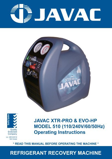
Quality SystemQualityEndorsedCompanyLic. QEC24519SAI GobalTMJAVAC XTR-PRO & EVO-HPMODEL 510 (110/240V/60/50Hz)Operating InstructionsCS SeriesCD SeriesJL SeriesJLT Series* READ THIS MANUAL BEFORE OPERATING THE <strong>MACHINE</strong> *COMMERCIAL <strong>REFRIGERANT</strong> & LABORATORY <strong>RECOVERY</strong> VACUUM <strong>MACHINE</strong> PUMPS
Thank you for purchasing a JAVAC Refrigerant Recovery Machine!The device combines an innovative refrigerant gas compression system with a rugged, moulded casethat is designed to offer maximum protection from damage during transit and normal handling. Withnormal use and with care as prescribed in this Manual, your machine will give you years of trouble-freeoperation.Safety First!When found on the machine, this international symbol is intended to alert the userto the presence of important operating, safety and maintenance (servicing) instructionsin this Manual. As used in the Manual, it is intended to draw your attention to criticalitems.It is important to read this entire Manual and be familiar with its contents before usingthe machine!The XTR-PRO and EVO-HP are Recovery Machines for a broad range of refrigerants. Recoveringrefrigerants into a separate storage cylinder involves a process of gas compression, resulting in highpressures within the machine, the connecting hoses and the storage cylinder. High-pressure systemsmust always be treated with care and respect to prevent careless accidents.EPA Certification:The JAVAC XTR-PRO and EVO-HP are EPA Certified machines in accordance with Section 608 of theClean Air Act. They have been independently tested and verified to be in conformance with itspublished specifications by the Air-Conditioning & Refrigeration Institute (ARI), USA.Product Safety:These units have been designed to meet the requirements of the Standard for Refrigerant RecoveryMachines, UL1963 and AS4211.3 - 1996. In order to fully meet safety requirements, the recoveryoperation must always be performed using an approved storage cylinder with a shutoff switch, which isproperly connected to the unit's Over Fill Protection circuit (available as factory option). If an approvedcylinder with overfill is not available always use an approved scale to monitor the cylinders capacity.Additionally, approved refrigerant hoses must be used which have shut-off devices within 12 inches ofthe ends to reduce the likelihood of refrigerant leakage to the atmosphere when changing cylinders orsetups.Responsibility:Only a Qualified Technician who has been properly trained in the care and use of suchequipment and in the recovery process itself must operate the JAVAC refrigerantrecovery devices. Use of this equipment by unqualified personnel is potentiallydangerous and should not be attempted.
INDEXJAVAC XTR-PRO & EVO HPTable of Contents:Page No.1.0 SAFETY PRECAUTIONS.............................................. 12.0 SPECIFICATIONS, FEATURES AND WARRANTY..... 33.0 SET UP AND OPERATION........................................... 63.1 Getting Started............................................................... 63.2 Normal Recovery Operation .......................................... 73.3 Purging The Recovery Machine..................................... 83.4 Push Pull Operation ....................................................... 93.5 Cooling The Recovery Cylinder ................................... 103.6 Special Operating Notes .............................................. 113.7 Storage ........................................................................ 124.0 APPROVED ACCESSORY ITEMS ............................. 125.0 MAINTENANCE .......................................................... 136.0 TROUBLESHOOTING ................................................ 157.0 SERVICE - CONSTRUCTION AND SCHEMATIC ...... 168.0 <strong>RECOVERY</strong> CYLINDER SAFETY .............................. 18Warranty Details ............................................................................. 5Service Return ................................................ Refer to Back Cover
1.0 SAFETY PRECAUTIONS:1.1 THIS EQUIPMENT MUST ALWAYS BE OPERATED BY A QUALIFIEDTECHNICIAN WHO IS FAMILIAR WITH <strong>REFRIGERANT</strong> SYSTEMS,<strong>REFRIGERANT</strong>S, <strong>REFRIGERANT</strong> SAFETY AND THE EPA REQUIREMENTS.1.2 READ THIS MANUAL and become familiar with the specifications andoperation of this machine prior to use.1.3 WEAR APPROPRIATE SAFETY PROTECTION APPAREL such as gloves,eye protection and foot protection when working on refrigeration systems.1.4 <strong>REFRIGERANT</strong> VAPOUR CAN BE HAZARDOUS AND ITS BYPRODUCTSCAN BE LETHAL - work only in well ventilated areas. When working indoors,ensure there is adequate airflow in the workspace and install a separate circulationfan if necessary. DO NOT WORK IN AN ENCLOSED AREA without special safetyequipment as appropriate for the conditions.1.5 KNOW THE PROPER SAFETY AND HANDLING REQUIREMENTS for theRefrigerant being recovered by reviewing the Material Safety Data Sheets (MSDS)and the Temperature - Vapour Pressure information.1.6 PERFORM LEAK DETECTION in accordance with recommended practice only.For best results use only a refrigerant detector such as the JAVAC D-TEK or TEK-Mate. NEVER USE OXYGEN for this process as it can become an explosivemixture in the presence of oil and pressure.1.7 NEVER OVERFILL A STORAGE CONTAINER. The safest approach is touse a certified storage cylinder with a “Cylinder Full” cutoff switch that isproperly connected to the optional Over Fill Protection Circuit. If the storagecylinder does not have a cutoff switch, or if PUSH-PULL OPERATION is used, theuse of a refrigerant scale, such as the JAVAC Wey-TEK, is required to preventoverfill. OVERFILLED CYLINDERS CAN RUPTURE EXPLOSIVELY!1.8 STORE <strong>REFRIGERANT</strong>S in a cool, dry place.1.9 SEPARATE DIFFERENT <strong>REFRIGERANT</strong>S. Avoid mixing refrigerants by usingseparate storage cylinders and filters for each type recovered.1
1.10 OPEN SERVICE OR CYLINDER VALVES SLOWLY to ensure that all connectionsare tight and there is no danger.1.11 DISCONNECT POWER before moving or servicing the recovery unit.CAUTION - these units should be opened only by a technically qualifiedperson who has been trained in basic electronics and refrigeration. The riskof ELECTRIC SHOCK and exposure to HOT compressor parts is possible ifthe unit is opened.1.12 WARNING - TO REDUCE THE RISK OF FIRE, EXTENSION CORDSSHOULD NOT BE USED with this equipment as the wiring can overheat underconditions of high current draw. If an extension cord is absolutely necessary, itslength should be as short as possible and it should contain size 16 AWG (1.291mm) or larger wiring.1.13 FLAMMABLE ENVIRONMENTS ARE DANGEROUS when any machine isused because motors and switches can generate sparks. This equipment shouldbe used in locations with mechanical ventilation providing at least four air changesper hour, or the equipment should be located at least 18” above the floor. DO NOTUSE THIS EQUIPMENT IN THE VICINITY OF SPILLED OR OPEN CONTAINERSOF GASOLINE OR ANY OTHER FLAMMABLE LIQUID.1.14 MOISTURE can cause severe damage when introduced to the internal parts of arefrigeration system. Ensure that care is exercised in the leak detection, recovery,repair and refilling of a system to prevent moisture from entering. Always use aquality high vacuum pump such as JAVAC Shark/Deluxe to ensure the system istotally dehydrated. An electronic total pressure gauge such as the Acravac shouldalso be used to monitor the pressure.1.15 USE CAUTION WHEN OPERATING OUTDOORS. Be certain that thepower cord, the cylinder safety cord and the unit itself are not placed in water orother potentially dangerous locations. While these recovery machines are verysafe to operate, using in environments such as hard rain or sand and dust stormsshould be avoided.1.16 CAUTION - EXERCISE CARE WHEN MOVING the equipment to preventthe risk of injury.2
2.0 SPECIFICATIONS, FEATURES AND WARRANTY2.1 XTR-Pro and EVO-HP SPECIFICATIONS:2.1.1 Refrigerants: EPA Certified to ARI 740-98 for refrigerants, R12, 134a,22 & 410A2.1.2 Safety: Designed to meet UL1963, AS standards & EU equivalents2.1.3 Power: 220/240 VAC, 50/60 Hz, 5 A(110VAC/50Hz,10A for XTR-PRO)2.1.4 Compressor: 1/3 HP Oil less, No inlet valve, AC Motor Drive2.1.5 Cooling: Fan/Motor2.1.6 Protection: High Pressure Switch Cutoff at 3200 KpaCompressor protected by separate circuit breakerCooling fan motor thermally protected80% Cylinder Full Shutoff available2.1.7 Pressure: Low side design pressure 1600 Kpa;High side design pressure 3200 Kpa2.1.8 Temperature: Operating Range 10 0 to 40 0 C2.1.9 Case: Blow-Moulded, High Impact Strength2.1.10 Size: 390mm L X 250mm W X 380mm H2.1.11 Weight: 12 KgRefrigerantLiquidRate(Kg/Hr)VapourRate(Kg/Hr)Push / PullRate.(Kg/hr)Shut OffVacuum(mm Hg)Residual TrappedRefrigerant(Kg)R-22 60 10 280 250
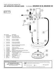
HP Cut Out LED – RedLP Override SwitchLP Cut Out LED - GreenCylinder Full LED - YellowCT – OFD SocketDetails of Optional PCC/CT-OFD Controls4
2.2 FEATURES:2.2.1 Designed with the highest quality components and manufactured in an ISO-9001 Registered facility.2.2.2 The JAVAC XTR-PRO and EVO-HP Refrigerant Recovery Machines utilize anew oil less compressor technology that is highly tolerant of liquid and is easierto maintain since it has no Inlet Valve.2.2.3 Factory fitted with a inlet particle filter which traps contaminants. This filter iseasy to remove, clean or replace in the event of restricted flow.2.2.4 Inlet (Suction) and Discharge pressure gauges allow the process to bemonitored from start to finish.2.2.5 The unit’s lightweight and excellent balance makes it easy to transport to thejob site and into difficult locations. The handle is easy to grasp and the unit isexceptionally well balanced.2.2.6 The PURGE operation can be accomplished without changing hoses.2.2.7 The high impact moulded case resists damage and is designed to protect thegauges, valve knobs and hose connection ports from incidental damagecaused during operation, handling and storage.2.3 WARRANTY:2.3.1 JAVAC warrants your XTR-Pro and EVO-HP Refrigerant Recovery Machinesto be free from defects of materials or workmanship for two years from thedate of purchase. JAVAC does not warrant any machine that has beensubjected to misuse, negligence, or accident, or has been repaired or alteredby anyone other than JAVAC. The XTR-PRO and EVO-HP are designed andmanufactured as general recovery machines for intermittent operation. Forinstance in commercial applications involving high duty cycles or continuousrunning, the XTR-PRO and EVO-HP are warranted for a period of 3 monthsfrom the date of purchase.2.3.2 The manufacturer warrants the Compressor for a period of one year. To keepthis WARRANTY in force it is required that the standard filter and a filter drierbe used on the Inlet Port or Hose at all times to prevent particulates fromentering the compressor. FAILURE TO USE A FILTER WILL VOID THECOMPRESSOR WARRANTY.2.3.3 JAVAC’s liability is limited to machines returned to JAVAC, returntransportation prepaid, not later than thirty (30) days after the warranty periodexpires, and which JAVAC judges to have malfunctioned because of defectivematerials or workmanship. JAVAC’s liability is limited to, at its option,repairing or replacing the defective machine or part.5
2.3.4 This WARRANTY is in lieu of all other warranties, express or implied, whetherof MERCHANTABILITY or of FITNESS FOR A PARTICULAR PURPOSE orotherwise. All such other warranties are expressly disclaimed. JAVACpractices continuous product research and improvement. We reserve the right tochange specifications and product design without notice. Such revisions do not entitlethe buyer to corresponding changes, improvements, additions or replacements forpreviously purchased equipment.2.3.5 JAVAC shall have no liability in excess of the price paid to JAVAC for themachine plus return transportation charges prepaid. JAVAC shall have noliability for any incidental or consequential damages. All such liabilities areEXCLUDED.3.0 SETUP AND OPERATION:3.1 GETTING STARTED:3.1.1 CAUTION: Only personnel who have been properly trained in the useand operation of Refrigeration Systems, Refrigerants and Service Equipmentshould operate this equipment. Failure to follow proper safety precautionscould result in personal injury or death.3.1.2 CAUTION: Review the full contents of this Manual before attempting touse the recovery machine in actual service.3.1.3 Identify the refrigerant to be recovered and prepare the recovery unit for useby installing an approved filter, hoses and optional shutoff cable or scale perthe diagram below. Refer to Section 4.0 of this Manual for approvedaccessories.3.1.4 Connect the AC Power cord to a circuit that is protected by a 4 amp breaker.Use an extension cord only when absolutely necessary to perform the service;be sure it is the minimum length required, that it contains a safety ground wireand that it contains wires sized 16 AWG (1.291 mm) or larger.3.1.5 Make sure the recovery unit is set in a stable position and that it is reasonablylevel; observe all safety precautions previously noted. Ensure that the faninlet and discharge areas on both sides of the machine are clear fromobstructions.3.1.6 Check all connections to ensure they are tight before starting the RecoveryOperation.3.1.7 The XTR-PRO and EVO-HP are liquid tolerant recovery machines. It isimportant to remember to START the machine before opening the INLETvalve. Should the compressor start to ‘Knock’, close the INLET valveimmediately and while it is still running, slowly open the valve back again.6
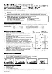
3.1.8 Use a Refrigerant Scale to ensure that the cylinder is not filled to morethan 80% of its capacity by weight. When operating in the NORMAL<strong>RECOVERY</strong> or PUSH-PULL mode without the cylinder shutoff it is possible tooverfill the cylinder. If you are not sure check the cylinder weight beforetransporting. Refer to Section 8.0 of this Manual. OVERFILLED CYLINDERSCAN RUPTURE EXPLOSIVELY!3.2 NORMAL <strong>RECOVERY</strong> OPERATION3.2.1 Connect all cables and hoses as described in Section 3.1 above and asshown in the diagram below. Ensure that they are tight and routed in such away that they will not interfere with the operation.SET-UP PROCEDURE FOR NORMAL <strong>REFRIGERANT</strong> <strong>RECOVERY</strong>3.2.2 Switch off the power to the unit being serviced. If the power switch is in aremote location, LOCK it out so that no one will accidentally turn it back on.3.2.3 Make sure that the discharge hose from the recovery unit to the RecoveryCylinder is attached to the LIQUID PORT. If cylinder contains refrigerant,partially open liquid valve and purge hose from recover unit discharge portend. If cylinder is empty and pre–evacuated, refer to section 3.2.4.4 and useincoming refrigerant to purge discharge hose from cylinder port end. Opencylinder liquid valve fully after purging hose.7
3.2.4 Set the recovery unit for <strong>RECOVERY</strong>.3.2.4.1 OPEN DISCHARGE valve (V3) to its fully open position.3.2.4.2 SET PURGE/<strong>RECOVERY</strong> valve (V2) to <strong>RECOVERY</strong> position.3.2.4.3 Open the Manifold Gauge VAPOUR valve slowly and verify that no leaksare present. Open vapour valve fully and partially open liquid valve. Do notattempt to recover 100% liquid3.2.4.4 At this point use incoming refrigerant to purge hose.3.2.5 Switch ON the recovery unit and verify that the compressor is operating andcooling air is exhausting from the back of the machine.3.2.6 MONITOR the inlet pressure (LP, Low Pressure Gauge) and SLOWLY OPENthe recovery unit INLET valve (V1) fully. If the compressor ‘knocks’ shut V1immediately, then close manifold liquid valve. Open V1 while the machine isrunning and continue to recover in vapour phase.3.2.7 Continue to operate until the required VACUUM has been pulled on thesystem (refer to Section 8.0 of this Manual), as indicated by the LP gauge.Switch OFF the recovery unit, CLOSE the INLET (V1), and wait for 5 minutes.If the Pressure in the system, as indicated on the Manifold Gauge, risesabove 0 Kpa, refrigerant is still present. If so, RESTART Recovery Machine,REOPEN the INLET (V1) and run until the required VACUUM is reachedagain. Repeat this process until all the refrigerant is removed resulting in afinal reading of 0 Kpa or less.3.2.8 TERMINATE the <strong>RECOVERY</strong> operation.3.2.8.1 CLOSE Manifold Gauge Liquid and Vapor valves.3.2.8.2 CLOSE XTR-Plus or EVO-HP INLET Valve (V1).3.2.8.3 Switch POWER OFF.3.2.8.4 It is a good practice to purge the Recovery Machine after each use. Referto section 3.3 of this manual.3.3 PURGING the recovery unit3.3.1 While the recovery machine is running, rotate INLET Valve (V1) to CLOSEposition.3.3.2 Rotate PURGE/<strong>RECOVERY</strong> valve (V2) to PURGE position. LeaveDISCHARGE (V3) open.3.3.3 Slowly rotate Inlet V1 to PURGE position.8
3.3.4 Observe LP Gauge and continue to run the unit until a VACUUM is achieved.Switch POWER OFF and CLOSE the Recovery Cylinder valve. Return INLETvalve (V1) to CLOSE position and close V3.3.3.5 IMPORTANT – Return V2 to <strong>RECOVERY</strong> Position3.3.6 CAUTION - THE DISCHARGE PORT AND HOSE WILL CONTAIN ASMALL AMOUNT OF <strong>REFRIGERANT</strong> UNDER PRESSURE. EXERCISECARE WHEN REMOVING THIS HOSE AND OPENING V3 VALVE.SET-UP PROCEDURE FOR PURGE3.3.7 REMOVE all hoses and cables and prepare the machine and the recoverycylinder for transport.3.3.8 When changing refrigerants or reconnecting to a cylinder always purge thehoses and the recovery machines ports with refrigerant, (or evacuate lines), toprevent air entering the recovery process.3.4 PUSH PULL OPERATION3.4.1 The PUSH PULL method is used to move a large amount of liquid refrigerantfrom the system being serviced to the recovery cylinder without passing itthrough the compressor. This method is only useful when more than 7 Kg ofliquid is known to be in the system and it can be easily isolated. DO NOTATTEMPT the PUSH PULL process unless you are sure of the situation.9
3.4.2 Connect the refrigerant hoses as shown below. Addition of a SIGHT GLASS inline between the system being serviced and the recovery cylinder is animportant aid to determine when all the liquid has been transferred and onlyvapour remains.3.4.3 This process uses the PULL from the exhausted recovery cylinder and theDischarge PUSH from the recovery unit to move the liquid refrigerant. Rates inexcess of 5 Kg per minute can be achieved by this procedure.3.4.4 The SCALE is required in this process to ensure that the cylinder is notoverfilled. The cylinder shutoff switch, if used, would stop the compressor butcould not guarantee that additional refrigerant flow would cease because of thedynamics of the system, thus possibly overfilling the cylinder.SET-UP PROCEDURE FOR PUSH-PULL METHOD3.5 COOLING THE <strong>RECOVERY</strong> CYLINDER3.5.1 The recovery unit can be used to PRE-cool (or SUB-cool) the recoverycylinder if the head pressure is too high to complete the recovery process.This can occur when working with certain refrigerants with a high vapourpressure in high ambient temperatures.3.5.2 If the recovery process stalls out because of high head pressure, stop therecovery unit, shut off the hose valves and reconfigure the setup as shownbelow. This can also be done before starting the recovery process but it mayhave marginal long term effect. NOTE: This will only work if there is at least 5Kg of liquid in the recovery cylinder to develop the necessary pressuredifferential required.10
3.5.3 POWER ON the recovery unit and ROTATE the DISCHARGE Valve (V3) toachieve a pressure differential of at least 700 Kpa between the LP Gauge andthe HP Gauge. KEEP THE HP BELOW 2500 Kpa on the HP Gauge to ensurethat the HP Cut-Off Switch will not actuate.3.5.4 After several minutes of running, the cylinder will be cold. POWER OFF therecovery unit and reconfigure the setup for NORMAL <strong>RECOVERY</strong>. Repeat asneeded.SET-UP PROCEDURE FOR SUB-COOLING METHOD3.6 SPECIAL OPERATING NOTES3.6.1 During normal operation, when the High Pressure switch activates, themachine will restart automatically when the head pressure drops belowapproximately 2500 Kpa.3.6.2 When the Optional Pressure Control Circuit is installed and when theHigh-Pressure switch activates, the machine must be cycled OFF and backON for the compressor to restart. The “High Pressure Cut Out” signal light(red) will illuminate when activated.3.6.3 When the optional Press Control Circuit is installed and when low pressureswitch activates on completion of recovery, the machine must be cycled OFFand back ON for compressor to restart. Green LED will illuminate when LP isactivated.3.6.4 When optional Low-Pressure Override is installed, compressor can berestarted after LP CUT-OUT activation by pressing the black switch. This willallow to achieve a further vacuum beyond the LP cutout range.11
3.6.5 When optional Cylinder/Tank Overfill Protection Device is installed and if theCT-OFD Cable is not connected or Cylinder/Tank is full, the yellow “CylinderFull” signal light will be illuminated. When this is the case, the compressionwill start briefly if the power is cycled OFF and ON again but will not run formore than a few seconds. This is normal operation.3.7 STORAGE3.7.1 When the recovery process has been completed, carefully coil the PowerCord, the Refrigerant Hoses and the Cylinder Overfill Protection Cord (ifused), ensuring that no dirt or foreign material is left in the ends or on theconnectors.3.7.2 Place the recovery unit in the service vehicle in its upright position and storethe hoses and cords nearby. Provide reasonable care to place the unit whereit will not be subjected to accidental damage due to shifting items duringtransit or to heavier objects being placed on its top.3.7.3 The unit can be stored safely in temperatures of 0 0 - 50 0 C and humidity levelsup to 95% RH. When stored in conditions that are severe, the unit may needto stabilize in the range 10 0 - 40 0 C before it will offer optimum operatingperformance. For best results, store the unit in an environmentally controlledarea when not in use.3.7.4 Always purge and vent the machine prior to storage, close V1 & V3 and leaveV2 in the Recover Position.4.0 APPROVED ACCESSORY ITEMS4.1 The XTR-PRO and EVO-HP Refrigerant Recovery Machines require the properaccessory items to ensure the best performance. The following items arespecifically identified to ensure safety and operational requirements are met.Check with your Wholesaler to ensure that the proper selections have been made.4.1.1 <strong>REFRIGERANT</strong> HOSES should be made with approved materials, should be asshort as possible to perform the required operations and should have shut-offdevices within 300mm of the ends. Approved hoses are:Refrigerant Hoses with UL Recognition and 20000 Kpa Burst Strength4.1.2 <strong>RECOVERY</strong> CYLINDERS should be approved and have an appropriatepressure rating for the refrigerant being recovered. Choose the size (normally20 or 60 Kg) that is right for the job, and be sure they have a cylinder full floatswitch. Approved cylinders are:Refrigerant cylinders with Brad Harrison 3 pin connectors12
4.1.3 FILTERS should be selected to protect the Inlet of the recovery machine fromparticles of dust, metal and other foreign materials that may be present in therefrigeration system. If servicing a system with a burned out compressor, 2 ormore FILTERS in series may be necessary, and they should be discardedimmediately after use. Approved filters are:Filters UL recognized/CSA listed for Refrigeration Service4.1.4 EXTENSION CORDS, when necessary, should be as short as possible andshould contain size 16 AWG (1.291 mm) or larger conductors. This isnecessary to avoid overheating during periods of high current draw andminimize the risk of fire. The longer the extension cord required at the work site,the larger the conductor size should be particularly for runs over 10m.4.1.5 CYLINDER/TANK OVER FILL DEVICE (CT – OFD), the JAVAC XTR-PRO andEVO-HP have been designed to incorporate an integrated Pressure ControlCircuit. The CT - OFD upgrades the machine to a latching High-Pressureswitch, (as opposed to automatic). Allows provision for an optional factory fittedLow Pressure switch, plus low voltage input, which, can be used to connect tocylinders, which incorporate, floats, cylinder scales or timers etc. Note: Becausenot all cylinders are available with Brad Harrison 3 pin connectors the facilitywill vary depending upon the market.5.0 MAINTENANCE5.1 Your recovery machine will provide many seasons of reliable service if it is properlymaintained. The actual maintenance requirements are minimal but important.5.2 Keep the unit clean by wiping it down with a damp cloth to remove dirt, oils, etc.prior to storage for the day. Standard household detergent or isopropyl alcoholmay be used if the unit is particularly dirty; in all cases, exercise care to preventliquids from entering the unit. Gasoline and other solvents are to be avoided asthey can damage the plastic enclosure and are hazardous.5.3 Clean inlet particle filter regularly. Discard internal filter screen if it is heavilycontaminated and replace with a new screen. Replace screen as per sketch forefficiency.13
5.4 Ensure that the Inlet and Discharge ports are protected and kept clean by replacingthe plastic caps after every use. For best results, keep a FILTER permanentlyconnected to the INLET port and change it regularly.5.5 Change HOSES periodically as they develop leaks and a build-up of contaminantsover time. Change hoses at least once per season.5.6 When storing the recovery machine for the season, or for long periods of time,PURGE the unit with an inert gas such as Nitrogen.5.7 When performance falls off it is likely that the compressor seals require replacing.This is normal with use and may occur after a year or two or more often, dependingupon the conditions that are prevalent during the recovery operations. Contactyour Wholesaler for assistance in selecting the proper maintenance kit.14
6.0 TROUBLESHOOTINGPROBLEM CAUSE ACTIONUnit will not start - compressor doesnot start; no light in Power Switch Power Cord not attached No voltage at receptacle / incorrectvoltage Attach Power Cord Verify voltage at Job SiteCompressor will not startCompressor starts but cuts out withina few minutes; pressure indication onHP gauge is highCompressor stops intermittentlyUnit overheatsRecovery process too slow Circuit breaker has opened Discharge pressure too high HP Switch has openedpermanently Insufficient pressure to close LPswitch (if fitted) Electronics failure in Motor, BridgeRectifier or Filter Capacitor / Relay Thermal cut-out has activated V2 is in Purge position and HPswitch activates V3 not open and HP switchactivates Recovery cylinder valve not open Blocked discharge hose Air in system/cylinder Fan not turning Vapour pressure of refrigerant incylinder is close to HP trip pointExcessive head pressure due to: High ambient temperature Restricted discharge hose Air in recovery cylinder Fan not turning Head pressure too high System refrigerant iced up Compressor seals are worn Inlet filter blocked Identify cause of breakeractivation, rectify and reset Reduce pressure and rotate V2 toPurge and back to Recovery Reduce pressure Factory service required Check connection, hoses, valves,gauges, system may not containrefrigerant Factory service required Allow motor to cool. If still notworking a factory service isrequired Rotate V2 to Recovery Rotate V3 to open position Open cylinder valve Check & clear blockage Bleed air from system/cylinder Factory service required Reduce cylinder temperature Reduce cylinder temperature Check & clear restriction Bleed air from cylinder Factory service required Reduce cylinder temperature orchange cylinders Throttle gauge manifold valves andV3 to reduce pressure differentialbetween LP and HP gauges Interrupt process to allow ice todissipate Rebuild compressor with service kit- check with wholesaler forassistance Remove filter and clean/replacecone screen15
7.0 SERVICE - CONSTRUCTION AND SCHEMATIC7.1 SERVICE7.1.1 The XTR-PRO and EVO-HP use only UL, CSA or TUV recognized electricalcomponents or components which have been specially designed for thisapplication.7.1.2 DO NOT CHANGE any of these components as the safety of the machinecould be compromised. All service work must be performed at a JAVACapproved facility in order to maintain the safety rating and the Warranty, ifapplicable.7.1.3 Technical assistance and service information can be obtained by calling thefactory at AUS 1300 786 771. UK (01642)-232-880 or the Organization whereyou purchased the recovery machineNOTE:Do not return a defective unit directly to the factory. Contactyour Wholesaler or the factory for assistance.7.1.4 The following Parts and Accessories for your XTR-PRO and EVO-HP areavailable through the same dealer from whom you purchased the unit.For electrical parts see 7.3 below:PART # DESCRIPTION QTYC11156 Thomas 510 CW75 Compressor: 230V AC 1QC20109 Fan blade (178mm) 1QD52610 Fan Cowling 1QD52605 Gauge, HP 1QD52606 Gauge, LP 1C11225 Relay 1C11223 Capacitor (Run) 230V 1C11224 Capacitor (Start) 230V 1QC20050 Circuit breaker 1QC20006 Socket, power in 1QC20005 On/Off Switch 1QS22053E Inlet hose 1QS22054E Discharge hose 1QC20017E Elbow Fitting (Discharge) 1QC20018E Elbow fitting (suction) 1QC20019E Elbow fitting (suction) extension 1QD52637 Wiring loom 1QA21102E Manifold Assembly 1QS22014 Knob Set (3) 1QD52602 Condenser 116
QD52654 Housing - Blue 1QD52612 Base Plate 1QD52613 Front Panel 1QS22020 Manifold Service Kit 1C11441 Compressor Seal Kit for Model 510 1R50631Cord Set AUS1QC20056Cord Set UKQS20127 Inlet Filter 1QC20011 Pressure Switch 1D52882 1/4" Copper Pipe 1QC20128 Thomas 510 compressor 110V 1QC20129 Capacitor (Start) 110V 1QC20130 Capacitor (Run) 110V 17.1.5 Only technically qualified personnel who are familiar with basic electronicsand refrigeration systems should install the Pressure Control Circuit.Disassembly of the unit to rebuild the compressor or to provide other repair workshould be referred to an approved service center as indicated above.7.2 CONSTRUCTION7.2.1 JAVAC recovery machines are constructed from the highest-grade materials toexacting standards. All assembly and testing is performed in an ISO-9001Registered facility.7.2.2 This unit is manufactured with environmentally compatible components, whichcan be substantially recycled at the end of the product’s useful life. Consult yourlocal agencies for proper recycling.7.2.3 The XTR-PRO and EVO-HP contain no hazardous materials.7.3 ELECTRICAL SCHEMATIC17ELECTRICAL SCHEMATIC DIAGRAM - MODELS XTR-Plus, XTR-PRO and EVO-HP
8.0 <strong>RECOVERY</strong> CYLINDER SAFETY8.1 Recovery Cylinders are tested to specific requirements to ensure that they willbe safe during the transportation process. These requirements ensure thesafety of the cylinder when it is filled to an appropriate level and when it isexposed to elevated temperatures, as in a truck or on a hot day outside.8.2 However, a cylinder that is overfilled may still be unsafe, even though the ratingis acceptable for the particular refrigerant. It is therefore extremely important,as noted in Sections 1 and 3 of this Manual, to ensure that the cylinder is notoverfilled.8.3 The cylinder must not be filled beyond 80% of its capacity. If a scale is tobe used, this weight can be determined by taking 80% of the Water Capacity(WC) weight that is marked on the cylinder and adding that to the Tare Weight(TW) of the cylinder. The TW is also marked on the cylinder.8.4 If the cylinder is partially filled and the TW is unknown, then the followingMAXIMUM TOTAL weights should be used for the recovery process using theweigh scale:22 Kg Cylinder - Fill to 28Kg, Total Maximum Weight65 Kg Cylinder - Fill to 75Kg Total Maximum Weight18