MCS Interface Card Pinouts
MCS Interface Card Pinouts
MCS Interface Card Pinouts
Create successful ePaper yourself
Turn your PDF publications into a flip-book with our unique Google optimized e-Paper software.
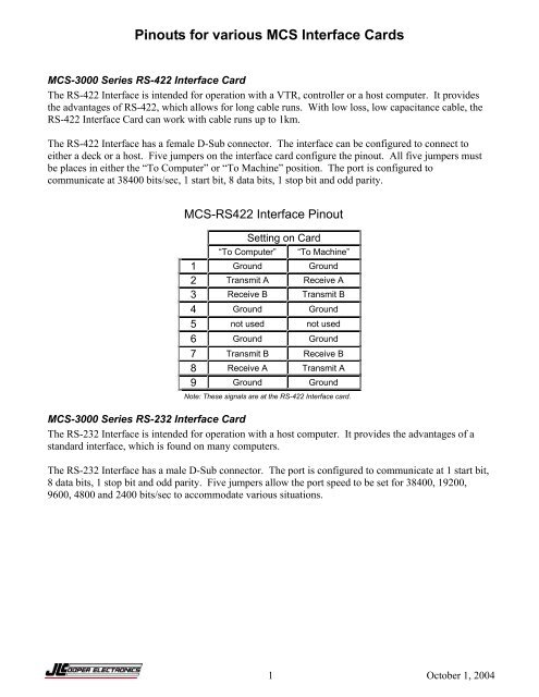
<strong>Pinouts</strong> for various <strong>MCS</strong> <strong>Interface</strong> <strong>Card</strong>s<strong>MCS</strong>-3000 Series RS-422 <strong>Interface</strong> <strong>Card</strong>The RS-422 <strong>Interface</strong> is intended for operation with a VTR, controller or a host computer. It providesthe advantages of RS-422, which allows for long cable runs. With low loss, low capacitance cable, theRS-422 <strong>Interface</strong> <strong>Card</strong> can work with cable runs up to 1km.The RS-422 <strong>Interface</strong> has a female D-Sub connector. The interface can be configured to connect toeither a deck or a host. Five jumpers on the interface card configure the pinout. All five jumpers mustbe places in either the “To Computer” or “To Machine” position. The port is configured tocommunicate at 38400 bits/sec, 1 start bit, 8 data bits, 1 stop bit and odd parity.<strong>MCS</strong>-RS422 <strong>Interface</strong> PinoutSetting on <strong>Card</strong>“To Computer” “To Machine”1 Ground Ground2 Transmit A Receive A3 Receive B Transmit B4 Ground Ground5 not used not used6 Ground Ground7 Transmit B Receive B8 Receive A Transmit A9 Ground GroundNote: These signals are at the RS-422 <strong>Interface</strong> card.<strong>MCS</strong>-3000 Series RS-232 <strong>Interface</strong> <strong>Card</strong>The RS-232 <strong>Interface</strong> is intended for operation with a host computer. It provides the advantages of astandard interface, which is found on many computers.The RS-232 <strong>Interface</strong> has a male D-Sub connector. The port is configured to communicate at 1 start bit,8 data bits, 1 stop bit and odd parity. Five jumpers allow the port speed to be set for 38400, 19200,9600, 4800 and 2400 bits/sec to accommodate various situations.1 October 1, 2004
<strong>Pinouts</strong> for various <strong>MCS</strong> <strong>Interface</strong> <strong>Card</strong>s<strong>MCS</strong>-RS232 <strong>Interface</strong> Pinout1 DCD*2 Transmit3 Receive5 Ground6 DSR*8 CTS*Note: These signals are at the RS-232 <strong>Interface</strong> card* These pins are not used by the card and areconnected together for ports that require handshake.<strong>MCS</strong>-3000 Series USB <strong>Interface</strong> <strong>Card</strong>The USB <strong>Interface</strong> is intended for operation with a host computer. It provides the advantages of astandard interface, which is found on most modern computers.The USB <strong>Interface</strong> has a female USB B type connector and uses the USB v1.1 protocol. For Windowscomputers, there is a driver that allows the device with this interface card to appear as a com port. Thisdriver can be downloaded from the JLCooper support web site,http://www.jlcooper.com/pages/downloads.html. With the driver, the virtual com port is configured tocommunicate at 38400 bits/sec, 1 start bit, 8 data bits, 1 stop bit and no parity.<strong>MCS</strong>-3000 Series Ethernet <strong>Interface</strong> <strong>Card</strong>The Ethernet <strong>Interface</strong> is intended for operation with a host computer. It provides the advantages of astandard interface, long cable runs, use over private/public/wired/wireless networks, the ability of beingshared among computers and the ability to work with any platform that supports TCP/IP.To use the Ethernet <strong>Interface</strong>, the software application MUST be written to specifically support theEthernet <strong>Interface</strong>. Consult your software’s users documentation for details on how to configure thesoftware.To configure the <strong>MCS</strong>-ClipShot Ethernet settings, an Ethernet <strong>Interface</strong> card must be in slot 1. You canverify this by visually checking slot 1 for the presence of an Ethernet card or by referring to the displayduring power up. If an Ethernet card is present at power up, the display will show:Ethernet <strong>Card</strong> in Slot #1No <strong>Card</strong> Found in Slot #2To set the IP address, refer to the documentation that came with your controller.Note: You must power cycle your controller for the Ethernet settings to take effect.2 October 1, 2004


