5450 Size White Color SMD Type LED - Ropla Elektronik Sp. z oo
5450 Size White Color SMD Type LED - Ropla Elektronik Sp. z oo
5450 Size White Color SMD Type LED - Ropla Elektronik Sp. z oo

You also want an ePaper? Increase the reach of your titles
YUMPU automatically turns print PDFs into web optimized ePapers that Google loves.
<strong>5450</strong> Flash <strong>White</strong> <strong>Color</strong> <strong>SMD</strong> <strong>Type</strong> <strong>LED</strong><strong>5450</strong> <strong>Size</strong> <strong>White</strong> <strong>Color</strong> <strong>SMD</strong> <strong>Type</strong> <strong>LED</strong>Part Number : M<strong>5450</strong>WH-EA2007. 02. 21Composition Check ApprovalNiNEX/ / // / /NiNEX Co., Ltd.http://www.ninex.bizHead Quarter/ Factory:#449-12, Mogok-Dong, PyongTaek-Si, Kyongki-Do, KoreaTel: 82-31-660-0800, Fax: 82-31-611-9048- 1 -
<strong>5450</strong> Flash <strong>White</strong> <strong>Color</strong> <strong>SMD</strong> <strong>Type</strong> <strong>LED</strong>1. General DescriptionThe document describes the specification of <strong>5450</strong> size, flash white color <strong>SMD</strong> type <strong>LED</strong>.Chip <strong>LED</strong>s, or <strong>SMD</strong> type <strong>LED</strong>s, are designed for automatic surface mounting process of ordinary electronicequipments. Some major applications include office electronic equipments, telecommunication equipmentsand household appliances.A generally acceptable driving current for a chip <strong>LED</strong> is relatively low compared to ordinary lighting devicesand high operation current or voltage may cause a catastrophic failure. All customers are expected to keep theguidance and the cautions described in the document and strongly recommended to consult NiNEX prior toapplying the devices for sensitive applications, particularly when exceptional quality and reliability arerequired.1-1. Features• <strong>Size</strong> 5.4 x 5.0 x 1.8 mm (L×W×H) – <strong>SMD</strong>(Surface-Mount Device) type• Encapsulating Silicone Resin : Phosphor dispersed water clear type• Viewing Angle (2Φ 1/2 ) : 120˚• <strong>Color</strong> C<strong>oo</strong>rdinates: x=0.262~0.317, y=0.245~0.305 according to CIE 1931, at If= 80mA• <strong>Color</strong> Mixing : AlInGaN based Blue <strong>LED</strong> Chip and special phosphor were used to convert blueemission to white color.• Electrodes for soldering : Ag plating on Copper1-2. Dimension(unit: mm, tolerance: ± 0.1mm)41324Common Anode13 2 N/APin Connection1. Common Anode2. N/A3. Cathode4. Cathode- 2 -
<strong>5450</strong> Flash <strong>White</strong> <strong>Color</strong> <strong>SMD</strong> <strong>Type</strong> <strong>LED</strong>2. <strong>Sp</strong>ecification2-1. Absolute Maximum Rating(T a = 25°C)Parameter Symbol Maximum Rating UnitsPower Dissipation P D 320 mWForward Current I F 80 mAPeak Forward Current *1 I F_PEAK 350 mAAllowable Reverse Current I R 100 mAOperation Temperature T OP -30 ~ +85 °CStorage Temperature T ST -40 ~ +100 °CSoldering Temperature*1: Duty ratio = 1/10, Pulse width = 10msT SOLReflow soldering (lead free): 260°C for 5sec.Reflow soldering (lead ): 240°C for 5sec2-2. Electrical and Optical Characteristics(T a = 25°C)Parameter Symbol Test Condition Min Max UnitsForward Voltage* 1 V F I F = 80mA 3.0 3.6 VLuminous Intensity* 2 I V I F = 80mA 2.0 7.0 cdx I F = 80mA 0.262 0.317<strong>Color</strong> C<strong>oo</strong>rdinate* 3 y I F = 80mA 0.245 0.305Reverse Current I R Zener Diode Protect μA*1: 0.05V tolerance for the forward voltage may be caused by measurement inaccuracy.*2: 10% tolerance for luminous intensity may be caused by measurement inaccuracy.*3: The measurement tolerance of color c<strong>oo</strong>rdinate is 0.01- 3 -
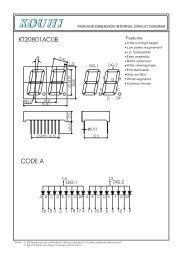
<strong>5450</strong> Flash <strong>White</strong> <strong>Color</strong> <strong>SMD</strong> <strong>Type</strong> <strong>LED</strong>3. Part Number DescriptionPart Number: M <strong>5450</strong> WH – E A1 2 3 4 53-1. Device <strong>Type</strong>: 1• A: Application Products• C: <strong>LED</strong> Chip (Dice)• D: Dot Matrix• I: Illumination Products• L: Lamp type <strong>LED</strong>• P: High Power Package <strong>LED</strong>• S: <strong>SMD</strong> type <strong>LED</strong>3-2. Package <strong>Size</strong>: 2, Package Thickness: 4(unit: mm)2 4 Package Dimension(W × L × T) Conventional Name1608 4 1.6 × 0.8 × 0.4 Chip <strong>LED</strong> 0.4t1608 6 1.6 × 0.8 × 0.6 Chip <strong>LED</strong> 0.6t1608 8 1.6 × 0.8 × 0.8 Chip <strong>LED</strong> 0.8t1612 4 1.6 × 1.25 × 0.4 Bi-<strong>Color</strong>(2 in 1) 0.4t1612 6 1.6 × 1.25 × 0.6 Bi-<strong>Color</strong>(2 in 1) 0.6t1612 8 1.6 × 1.25 × 0.8 Bi-<strong>Color</strong>(2 in 1) 0.8t1615 4 1.6 × 1.5 × 0.4 Full <strong>Color</strong>(3 in 1) 0.4t1615 6 1.6 × 1.5 × 0.6 Full <strong>Color</strong>(3 in 1) 0.6t1615 8 1.6 × 1.5 × 0.8 Full <strong>Color</strong>(3 in 1) 0.8t3528 E 3.5 × 2.8 × 1.8 3528 Package3530 A 3.5 × 3.0 × 1.07 Flash <strong>LED</strong>4014 6 4.0 × 1.4 × 0.6 Sideview 0.6t4014 8 4.0 × 1.4 × 0.8 Sideview 0.8t4014 1 4.0 × 1.4 × 1.0 Sideview 1.0t<strong>5450</strong> E 5.4 × 5.0 × 1.8 <strong>5450</strong> Package- 4 -
<strong>5450</strong> Flash <strong>White</strong> <strong>Color</strong> <strong>SMD</strong> <strong>Type</strong> <strong>LED</strong>3-3. Emission <strong>Color</strong>: 3• Emission color from 1 chip in 1 packageDescription RE OR AM YL YG GN BL VLEmission <strong>Color</strong> Red Orange Amber Yellow Yellow-Green Green Blue Violet• Converted color emission from 1 chip in 1 packageDescription WH BW VW YW WWEmission <strong>Color</strong> <strong>White</strong> Blue-<strong>White</strong> Violet-<strong>White</strong> Yellow-<strong>White</strong> Warm <strong>White</strong>• Multi color emission from multi chip in 1 packageDescription GR BR BG FC 7C<strong>Color</strong> Green+Red Blue+Red Blue+Green Red+Green+Blue Red+Yellow-Green+Blue3-4. Package <strong>Type</strong> Information: 5Description Information RemarksA Common Anode Multi Chip PackageB Anode & Cathode for each dice Multi Chip PackageC Common Cathode Multi Chip PackageDTDiffused EpoxyTransparent EpoxyY Yellow Phosphor <strong>White</strong> color applicationZ Include in Zener Diode 1615, 4014, 3528 Package- 5 -
4-1. Chromaticity C<strong>oo</strong>rdinates *1 (T a =25°C) *2<strong>5450</strong> Flash <strong>White</strong> <strong>Color</strong> <strong>SMD</strong> <strong>Type</strong> <strong>LED</strong>4. Sorting Ranks1 2 3 4Cx Cy Cx Cy Cx Cx Cy Cx0.282 0.245 0.290 0.260 0.299 0.275 0.272 0.2450.272 0.245 0.280 0.260 0.289 0.275 0.262 0.2450.280 0.260 0.289 0.275 0.298 0.290 0.270 0.260Rank0.290 0.260 0.299 0.275 0.308 0.290 0.280 0.2605 6 7 8Cx Cy Cx Cy Cx Cx Cy Cx0.280 0.260 0.289 0.275 0.298 0.290 0.288 0.2900.270 0.260 0.279 0.275 0.307 0.305 0.297 0.3050.279 0.275 0.288 0.290 0.317 0.305 0.307 0.3050.289 0.275 0.298 0.290 0.308 0.290 0.298 0.290*1: The CIE (1931) standard colorimetric System*2: Measurement Condition: 20ms pulse @ I F =50mA, 0.01sr (CIE.<strong>LED</strong>_B)0.320.310.3870.290.28630.27520.260.25410.240.25 0.26 0.27 0.28 0.29 0.3 0.31 0.32 0.33- 6 -
4-2. Luminous Intensity *1 (unit: cd, T a =25°C) *24-3. Forward Voltage *1 (unit: V, T a =25°C) *2<strong>5450</strong> Flash <strong>White</strong> <strong>Color</strong> <strong>SMD</strong> <strong>Type</strong> <strong>LED</strong>Rank Min. Max.A 2.0 2.5B 2.5 3.0C 3.0 3.5D 3.5 4.0E 4.0 5.0F 5.0 6.0G 6.0 7.0*1: 10% tolerance for luminous intensity may be caused by measurement inaccuracy.*2: Measurement Condition: 20ms pulse @ I F =80mARank Min. Max.a 3.0 3.1b 3.1 3.2c 3.2 3.3d 3.3 3.4e 3.4 3.5f 3.5 3.6*1: 0.05V tolerance for the forward voltage may be caused by measurement inaccuracy.*2: Measurement Condition: 20ms pulse @ I F =80mA• Each product belongs to a rank for each sorting parameter.• Combination of the ranks composes sorting bins(ex. 1Bc, 2Cc, etc)• Products which belong to the same sorting bin are taped together.• Bin mixing is not allowed within a reel.- 7 -
<strong>5450</strong> Flash <strong>White</strong> <strong>Color</strong> <strong>SMD</strong> <strong>Type</strong> <strong>LED</strong>5. Taping5-1. Carrier Tape *1 Dimension(unit: mm)*1: Material: PS, Conductivity: 10 9 Ω ~ 10 12 Ω5-2. Reel Dimension *1 (unit: mm)*1: Material: PS, Conductivity: 10 4 Ω ~ 10 5 Ω- 8 -
<strong>5450</strong> Flash <strong>White</strong> <strong>Color</strong> <strong>SMD</strong> <strong>Type</strong> <strong>LED</strong>6. Packing *1 (unit: mm)Packing unit <strong>Size</strong> (W × L × D) Quantity (ea)Antistatic shielding bag (1 Reel) 220 × 250 800Inner carton box (8 Reels) 220 × 220 × 145 6,400Outer carton box (48 Reels) 450 × 300 × 230 38,400*1: Each reel sealed in an antistatic shielding bag with silica-gelAntistatic shielding bagInner carton boxLabelOuter carton boxPART NO M<strong>5450</strong>WH-EA Q'TY 800LOT NONM<strong>5450</strong>WHEA-A3FT4B2-001DATE 2006-06-14BIN NO 1AaNINEX Co.,Ltd.- 9 -
<strong>5450</strong> Flash <strong>White</strong> <strong>Color</strong> <strong>SMD</strong> <strong>Type</strong> <strong>LED</strong>7. Lot Number DescriptionLot Number: NM<strong>5450</strong>WHEA-A1BP 4 B 2 - 0001 234 5• NiNEX Product Number: 1• Production Year (3 for 2003, 4 for 2004, 5 for 2005): 2• Production Month 3 and Date 4Month Jan Feb Mar Apr May Jun Jul Aug Sep Oct Nov Dec3 A B C D E F G H I J K LDate 1 2 3 4 5 6 7 8 9 10 11 12 13 14 154 1 2 3 4 5 6 7 8 9 10 A B C D EDate 16 17 18 19 20 21 22 23 24 25 26 27 28 29 304 F G H I J K L M N O P Q R S T• Serial No.: 58. Soldering*1, *28-1. Recommended Soldering ConditionReflow SolderingManual SolderingLead solder Lead-free * 2 Lead Solder Lead-free* 2Pre-heating 140 ~ 160 °C 180~200°C Temperature max. 300°C max. 350°C.Pre-heat time 60 ~ 120 sec. 120 sec. Time max. 3 sec. max. 3 sec.Peak temperature max. 240°C max. 260°CSoldering time max. 5 sec. max. 5 sec.No multiple soldering allowed*1: After reflow soldering, rapid c<strong>oo</strong>ling should be avoided, and this condition does not guarantee repetition ofreflow process.*2: N 2 reflow is recommended- 10 -
<strong>5450</strong> Flash <strong>White</strong> <strong>Color</strong> <strong>SMD</strong> <strong>Type</strong> <strong>LED</strong>8-2. Recommended Reflow Soldering Profile● Lead Solder5sec. max.● Lead-free Solder5sec. max.Temperature (℃ )140 ~ 160℃ 2.5 ~ 5 ℃ / s2.5 ~ 5 ℃ / s120 sec. max 60 sec. max.240℃ max.Temperature (℃)180 ~ 200℃ 1 ~ 5 ℃ / s1 ~ 5 ℃ / s120 sec. max. 60 sec. max.260℃ max.Time (sec.)Time (sec.)8-3. Recommended Soldering Pattern(Unit : mm)• During the soldering process, keep the minimum clearance between the resin and the soldering point.• Resin should not contact molten solder.• No mechanical distortion or stress allowed after soldering.• During soldering, do not apply any stress to the lead frame, particularly when heated.• A soldering iron with a grounded tip is recommended.An isolator should also be installed where risk of static generation is high.- 11 -
<strong>5450</strong> Flash <strong>White</strong> <strong>Color</strong> <strong>SMD</strong> <strong>Type</strong> <strong>LED</strong>9. Cautions9-1. Safety• Customers should comply with the laws and public regulations concerning safety.• Operation temperature or driving current may affect emission color.Please check sorting condition and characteristic diagram to estimate color shift.• Moisture and dust may affect reliability issues.Do not open the shielding bag under humid or dirty environment.• When installing the product in PCB, the device should not contact with other components.• Do not apply force to the <strong>LED</strong> under high-temperature condition.• Do not apply friction to the <strong>LED</strong> using hard material.• Avoid exposure to chemicals which may dissolve the <strong>LED</strong> package and the epoxy.• Use IPA(Isopropyl Alcohol) as a solvent when washing is required.9-2. Static Electricity• These products are sensitive to static electricity.Anti–electrostatic glove or wristband is recommended when handling the <strong>LED</strong>s.• A protection device should be installed in the <strong>LED</strong> driving circuit to eliminate orminimize the surge current effect.• Proper grounding of Products, use of conductive mat, semi-conductive working uniform and shoes,and semi-conductive containers are considered to be effective as countermeasures againststatic electricity and surge.9-3. Storage Condition• Before opening the anti-static shielding package:<strong>LED</strong>s should be kept at 30°C or less and RH 80% or less.Maximum acceptable storage period is 6 months.• After opening the anti-static shielding package:<strong>LED</strong>s should be kept at 30°C or less and RH 70% or less.<strong>LED</strong>s should be soldered within 7 days after opening the package.- 12 -
<strong>5450</strong> Flash <strong>White</strong> <strong>Color</strong> <strong>SMD</strong> <strong>Type</strong> <strong>LED</strong>10. Characteristic Diagram● Forward Voltage vs.Forward Current● Ambient Temperature vs.Allowable Forward CurrentForward Current (mA)100101Ta=25℃1 2 3 4 5Forward Voltage (V)Allowable Forward Current(mA)16014012010080604020Ta=25 C0-20 0 20 40 60 80 100Ambient Temperature( C)● Ambient Temperature vs.Forward Voltage● Ambient Temperature vs.Relative LuminosityForward Voltage (V)4.44.03.63.22.82.42.0IF=20mA-40 -20 0 20 40 60 80 100Ambient Temperature (℃)Relative Luminosity (a.u.)1.6IF=20mA1.41.21.00.80.60.4-40 -20 0 20 40 60 80 100Ambient Temperature (℃)- 13 -
<strong>5450</strong> Flash <strong>White</strong> <strong>Color</strong> <strong>SMD</strong> <strong>Type</strong> <strong>LED</strong>● Forward Current vs.Relative Luminosity● Forward Current vs.Chromaticity C<strong>oo</strong>rdinate2.50.36Relative Luminosity (a.u.)2.01.51.00.50.0Ta=25℃0 10 20 30 40 50Forward Current (mA)0.35Ta=25 C0.340.33y 0.3210mA0.310.3020mA0.2960mA0.2880mA0.28 0.29 0.30 0.31 0.32 0.33 0.34x● <strong>Sp</strong>ectrum● Radiation DiagramEmission Intensity (a.u.)1.00.5Ta=25℃Ta=25℃IF=80mA0.0350 450 550 650 750Wavelength (nm)- 14 -
<strong>5450</strong> Flash <strong>White</strong> <strong>Color</strong> <strong>SMD</strong> <strong>Type</strong> <strong>LED</strong>11. Reliability Test11-1. Test items and resultsTest Item Reference Standard Test ConditionsNumber ofDamaged PartsNormal TemperatureLifetime TestMIL-STD-883:1005JIS C 7035T a =25 ℃ I f =100mATest Time=1,000hrs0/22High TemperatureOperating Life (HTOL)MIL STD 883E-1005EIAJ ED 4701-100T a =85℃ I f =20mATest Time=1,000hrs0/22Temperature HumidityBias (THB)EIAJ ED 4701-100T a =60 ℃ / RH=90%I f =60mATest Time=500hrs0/22Temperature CycleMIL-STD-883 :1010EIAJ ED 4701-100-30 ℃ ~ 25 ℃ ~ 100 ℃ ~ 25℃30min 5min 30min 5minTest Time=50cycles0/22High TemperatureStorageMIL-STD-883 : 1008EIAJ ED 4701-200T a =100℃Test Time=1,000hrs0/22Low TemperatureStorageEIAJ ED 4701-200T a =-40℃Test Time=1,000hrs0/22ESD(Electro-staticDischarge) RatingMIL STD-883E : 3015EIAJ ED 4701-300HBM(Human Body Model)C=100pF R =1.5KΩDischarge times : 3 times0/2211-2. Criteria of failure for the reliabilityTest Item Symbol Test Condition Judgment CriteriaForward Voltage V f I f = 20mA V f > 1.1×U.S.L *1Luminous Intensity I v I f = 20mA I v < 0.7×Initial valueESD Rating *2 ESD HBM Class 2 or more*1: U.S.L : Upper Standard Level*2: ESD Rating forward directed by HBM (Human Body Model)Classification *1 Class 1 Class 2 Class 3A Class 3BWithstand Voltage 250 - 1,999V 2,000 - 3,999V 4,000 -7,999V 8,000V or more*1: EIAJ ED 4701-300- 15 -
<strong>5450</strong> Flash <strong>White</strong> <strong>Color</strong> <strong>SMD</strong> <strong>Type</strong> <strong>LED</strong>Part Number.M<strong>5450</strong>WH-EADocument IDEvents S/N Date Summary of Revision Remarks0 2006. 06. 14 Newly Establishment -1 2007. 02. 21Revise Chromaticity C<strong>oo</strong>rdinates &IV, VF rank- 16 -