Datasheet PDF - Xortec.de
Datasheet PDF - Xortec.de
Datasheet PDF - Xortec.de

You also want an ePaper? Increase the reach of your titles
YUMPU automatically turns print PDFs into web optimized ePapers that Google loves.
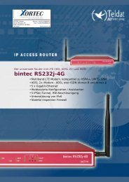
Data SheetOptimux-34, Optimux-2516-Channel E1/T1, Ethernet or Data over E3 or FiberMultiplexers• Up to 16 E1/T1 links and high-speed data or Ethernet traffic multiplexed intofiber optic uplink• E3 copper uplink for Optimux-34• Single-mo<strong>de</strong>, multimo<strong>de</strong>, single-mo<strong>de</strong> over single fiber SFP-based interfaces• Range of up to 110 km (68 miles)Multiplex any trafficover fiber• Redundancy provi<strong>de</strong>d by optional second modular, hot-swappable power supplyand second uplink• Card versions for up to 12 cards in an LRS-102 rackOptimux-34 and Optimux-25 provi<strong>de</strong> asimple, flexible, and cost-effective solutionfor transporting multiple E1/T1 links,high-speed data or Ethernet over an E3copper or fiber link to distances of up to110 km (68 miles).The fiber optic link is available withsingle-mo<strong>de</strong>, multimo<strong>de</strong>, and single-mo<strong>de</strong>over single fiber interfaces. TheOptimux-34 uplink is compliant withE3 standards and additionallyfeatures coax interfaces.The unit provi<strong>de</strong>s up to 16 E1/T1 links,some of which can be replaced byhigh-speed data or 10/100BaseT userEthernet traffic, selectable by the user(see Table 1).The Access Company
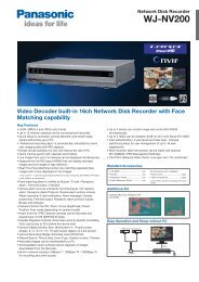
Optimux-34, Optimux-2516-Channel E1/T1, Ethernet or Data over E3 or Fiber MultiplexersThe Optimux <strong>de</strong>vices are supplied with a10/100BaseT Ethernet user port. Instandalone units, this port is activated viaa software key purchased from RAD.TimingThe Optimux <strong>de</strong>vices transmit each E1/T1channel separately so that the clock ofeach E1/T1 channel is in<strong>de</strong>pen<strong>de</strong>nt.Link RedundancyAn optional second link provi<strong>de</strong>s linkbackup, using automatic switchover uponlink failure.Uplink InterfacesVarious interfaces (based on SFPtransceivers) are available for both theactive and the backup uplinks (see Table 2and Or<strong>de</strong>ring Options):• Electrical via coax (SMB) connector(Optimux-34, OP-34C only)• 1310 nm short or long-haul laser and1550 nm long-haul laser interfaces forexten<strong>de</strong>d range over single-mo<strong>de</strong> fiber• Single fiber interface using WDMtechnology, where the laser transmitsignal is at a different wavelengthfrom the receive signal (1310 nm and1550 nm)• Single fiber single wavelength interfaceusing SC/APC connector, with a1310 nm laser dio<strong>de</strong> for singlewavelength operation.It is strongly recommen<strong>de</strong>d to or<strong>de</strong>r this<strong>de</strong>vice with original RAD SFPs installed.This will ensure that prior to shipping, RADhas performed comprehensive functionalquality tests on the entire assembled unit,including the SFP <strong>de</strong>vices. RAD cannotguarantee full compliance to productspecifications for units using non-RADSFPs.DiagnosticsOptimux features comprehensive test anddiagnostic capabilities that inclu<strong>de</strong> localand remote loopbacks on the uplinkinterface and on each E1/T1 port. A localloopback is also supported on the optionalV.35 user port of the standalone <strong>de</strong>vices.To ease system diagnostics, Optimuxfeatures LED status indicators and AISalarm generation and recognition.The standalone <strong>de</strong>vices also feature drycontact closure upon link failure. Anoptional alarm port is available with dryrelay contacts for major and minor alarms.Figure 1. Ethernet, Voice, Data and Vi<strong>de</strong>o Services Over Fiber Optic Link
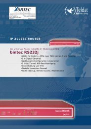
Data SheetSTANDALONE DEVICESThe standalone <strong>de</strong>vices can be suppliedwith one V.35 (2 MB/sec) channel thatreplaces channel 16 by user activation.ManagementManagement and diagnostics can beperformed via:• ASCII terminal• Telnet• RAD's Web-based managementapplication• RADview, RAD's SNMP-basedmanagement application.PhysicalOptimux-25 is a compact, 1U-high unit.Optimux-34 is available in two versions:• 1U-high unit with balanced E1interface, RJ-45 connectors• 2U-high unit with unbalanced E1interface, BNC or IEC-169/13connectors.The units can be mounted in a 19-inchrack.PowerThe standalone power supply is awi<strong>de</strong>-range AC/DC power supply that canbe connected to either an AC powersource (100 to 240 VAC), or a DC powersource (–48 VDC).An optional second power supply provi<strong>de</strong>spower redundancy.Figure 2. Service Extension over Wireless Link
Optimux-34, Optimux-2516-Channel E1/T1, Ethernet or Data over E3 or Fiber MultiplexersCARD MODULESThe OP-34C and OP-25C multiplexers arecards <strong>de</strong>signed for operation in theLRS-102 chassis. The LRS-102 chassis cancontain up to 12 cards (192 links). AnOptimux link provi<strong>de</strong>s a simple andlow-cost solution for connectivity overdistances of up to 110 km (68 miles).Link InterfacesPluggable SFP units provi<strong>de</strong> the linkinterfaces. A wi<strong>de</strong> variety ofoptical/electrical interfaces are availablefor or<strong>de</strong>ring as single or dual modules (seeTable 2 and Or<strong>de</strong>ring Options).It is strongly recommen<strong>de</strong>d to or<strong>de</strong>r this<strong>de</strong>vice with original RAD SFPs installed.This will ensure that prior to shipping, RADhas performed comprehensive functionalquality tests on the entire assembled unit,including the SFP <strong>de</strong>vices. RAD cannotguarantee full compliance to productspecifications for units using non-RADSFPs.ManagementSetup, control, and diagnostics areperformed by the LRS-102 managementrack (see LRS-102 Data Sheet).PhysicalEach card fits in a single slot of theLRS-102 chassis.Note: For OP-34C/OP-25C cards operating inthe Megaplex-4100 enclosure, refer to aseparate OP-34C/OP-25C data sheet inclu<strong>de</strong>dinto the Megaplex-4100 fol<strong>de</strong>r.PowerThe power for cards is provi<strong>de</strong>d by theLRS-102 power supply.Table 1. Bandwidth Available for Ethernet TrafficMo<strong>de</strong>lOptimux-34,OP-34CMaximum Numberof Active PortsBandwidth Available for EthernetTraffic16 E1 No bandwidth available12 E1 8 Mbps8 E1 16 Mbps4 E1 24 MbpsNo port32 Mbps16 T1 No bandwidth availableOptimux-25,OP-25C12 T1 6 Mbps8 T1 12 Mbps4 T1 18 MbpsNo port25 Mbps
Data SheetSpecificationsE1/T1 INTERFACENumber of Channels16Data RateE1: 2048 kbpsT1: 1544 kbpsImpedance120Ω, E1 balanced100Ω, T1 balanced75Ω, E1 unbalancedConnectorsOptimux-34E1 Balanced: RJ-45E1 Unbalanced: BNC or IEC-169/13 (in 2Uunit)Note: For balanced and unbalanced channels in thesame unit, or<strong>de</strong>r a 1U-high unit and oneCBL-RJ45/BNC/E1/X adaptor cable for each pair ofBNC connectors.Optimux-25T1 Balanced: RJ-45OP-34C, OP-25CTwo DB-44 connectors on the frontmodule panel convertible to 16 balancedinterfaces via adaptor cables. WithOP-34C, unbalanced interfaces are alsoavailable (see Or<strong>de</strong>ring)LINK INTERFACES(MAIN AND BACKUP)Data RateOptimux-34, OP-34C: E3 (34.368 Mbps)Optimux-25, OP-25C: RAD proprietary(25.910 Mbps)Interface OptionsSee Table 2ConnectorsSFP interfaces with LC connectors orSC/APC for single wavelength single fiberStandardsOP-34: ITU G.703, G.742, G.751, G.823,G.955, IEEE 802.3OP-25: ITU G.703, G.824, G.955, IEEE802.3HIGH-SPEED INTERFACE (STANDALONEONLY)TypeV.35ConnectorDB-25 (ISO-2110 or Telebras pinout)ETHERNET INTERFACESType10/100BaseTConnectorsStandalone: RJ-45Card: lower DB-44 connector, via adaptorcablesCONTROL PORT (STANDALONE UNITSONLY)TypeRS-232 DCE asynchronousData Rate9.6, 19.2, 38.4, 57.6, 115.2 kbpsConnector9-pin D-type femaleALARM PORT (STANDALONE UNITSONLY)TypeDry relay contacts for major and minoralarmsConnector9-pin D-type femaleSTANDALONE INDICATORSPowerOFF – Not poweredON (green) – Normal operationON (red) – Power malfunctionSystemTST (yellow) – Self-test or loopFLT (red) – System faultTable 2. Link Interface OptionsModule NameTransmitter Type andWavelengthConnectorTypeFiber TypeTypical OutputPowerReceiverSensitivityTypical Range(Or<strong>de</strong>ring Option) [nm] [dBm] [dBm] [km] [miles]SFP-12(Optimux-34,OP-34C only)– SMB Coax cable – – (Per ITU-T G.703standard)SFP-1 LED, 1310 LC 62.5/125 Multimo<strong>de</strong> -18 -31 6.5 4.0SFP-2 Laser, 1310 LC 9/125 Single mo<strong>de</strong> -12 -31 38 23.6SFP-3 Long haul laser, 1310 LC 9/125 Single mo<strong>de</strong> -2 -34 70 43.4SFP-4 Long haul laser, 1550 LC 9/125 Single mo<strong>de</strong> -2 -34 110 68.3SFP-10aLaser WDM,Transmit: 1310,Receive: 1550LC9/125 Single mo<strong>de</strong>(single fiber)-12 -30 40 24.8SFP-10bLaser WDM,Transmit: 1550,Receive: 1310LC9/125 Single mo<strong>de</strong>(single fiber)-12 -30 40 24.8Note: Typical ranges are calculated according to attenuation of 0.4 dB/km for 1310 nm, 0.25 dB/km for 1550 nm for single mo<strong>de</strong> fiber.
Optimux-34, Optimux-2516-Channel E1/T1, Ethernet or Data over E3 or Fiber MultiplexersLink SFP (per port)SYNC LOSS (red) – Signal loss or frameloss <strong>de</strong>tected on uplinkAIS (yellow) – AIS <strong>de</strong>tected on uplinkUser Ethernet PortLINK/ACT (lights yellow) – LAN up statusLINK/ACT (flashes yellow) – LAN traffictransfer100 (green) – On: 100 Mbps operation100 (green) – Off: 10 Mbps operationE1/T1 Interfaces (per port)SYNC LOSS (red) – Signal loss <strong>de</strong>tected onE1/T1 linkAIS (yellow) – AIS <strong>de</strong>tected on E1/T1 linkManagement PortLINK/ACT (lights yellow) – LAN up statusLINK/ACT (flashes yellow) – LAN traffictransfer100 (green) – On: 100 Mbps operation100 (green) – Off: 10 Mbps operationCARD INDICATORSEthernet PortLINK/ACTOn (yellow): link is upOff: link is downFlashes: frames are transmitted100On (green): 100 Mbps mo<strong>de</strong>Off: 10 Mbps mo<strong>de</strong>Link SFP (per port)SYNC LOSS (red) – Signal loss or frameloss <strong>de</strong>tected on uplinkAIS (yellow) – AIS <strong>de</strong>tected on uplinkGENERALDiagnosticsLocal and remote loopbacks on uplink andon each E1/T1 portLocal loopback on optional V.35 user port((Optimux-34 only)TimingUplink: internal, loopbackE1/T1 port: transferred transparently,in<strong>de</strong>pen<strong>de</strong>nt for each channelV.35: internal, external, loopbackPowerStandalone: wi<strong>de</strong> range power supplyAC: 100 to 240 VACDC: –48 VDC (–40 to –72 VDC)Card: supplied by LRS-102Power ConsumptionStandalone:AC: 32 VA maxDC: 13W maxCard: 10.4W maxPhysical1U-highHeight: 4.4 cm (1.8 in)Width: 44.0 cm (17.0 in)Depth: 24.0 cm (9.0 in)Weight: 3.5 kg (8.0 lb)2U-high (Optimux-34 only)Height: 8.8 cm (3.5 in)Width: 44.0 cm (17.0 in)Depth: 24.0 cm (9.0 in)Weight: 4.0 kg (9.0 lb)Card: fits into the LRS-102 rackEnvironmentTemperature: 0°–50°C (32°–122°F)Humidity: Up to 90%, non-con<strong>de</strong>nsingTable 3. Optimux Comparison ChartFeature Optimux-108 Optimux-106 Optimux-34 Optimux-25 Optimux-45/45L Optimux-1551 Optimux-1553Uplink Fiber Optic Fiber Optic E3, Fiber Optic Fiber Optic T3, Fiber Optic Copper,STM-1/OC-3Copper,STM-1/OC-3Bandwidth (Mbps) 108 81 34 25 45 155 155Number of trunks 4 E1 4 T1 16 E1 16 T1 21 E128 T121/42/63 E128/56/84 T13 E33 T3Ethernet support – – –Card version forLRS-102 Special featuresRedundant,hot-swappableuplinksRedundant,hot-swappableuplinksSFP-baseduplinksSFP-baseduplinksRing support(Optimux-45)Full redundancyFull redundancy
Data SheetOr<strong>de</strong>ringSTANDALONE UNITSOP-34/*/?/+/%/$/#16-Channel E1, Ethernet or Data over E3or Fiber MultiplexerOP-25/*/+/%/$/#16-Channel T1, Ethernet or Data overFiber MultiplexerLegend* Power supply:Note: Optimux-34/25 is suppliedwith one OP-34/25-PS wi<strong>de</strong> rangepower supply.R Dual power supply(110-240 AC, -48 VDC)DC Single +24/-48 VDCDCR Dual +24/-48 VDC? E1 connector for Optimux-34:B Balanced (RJ-45, 1U-highunit)U Unbalanced (BNC, 2U-highunit)UBR Unbalanced (IEC-169/13,2U-high unit)+ Alarm port (Default=no alarm port):A Alarm port% V.35 user port (Default=no V.35user port):V35 DB-25 connector withISO-2110 pinoutV35T DB-25 connector withTelebras pinout$ Activation key (Default=noactivation key):PACK1 Software key foractivating the10/100BaseT EthernetportNote: It is strongly recommen<strong>de</strong>d to or<strong>de</strong>r this<strong>de</strong>vice with original RAD SFPs installed. This willensure that prior to shipping, RAD has performedcomprehensive functional quality tests on theentire assembled unit, including the SFP <strong>de</strong>vices.RAD cannot guarantee full compliance to productspecifications for units using non-RAD SFPs.# Uplink interface:SFP-12 Electrical coax, SMB(Optimux-34 only)SFP-1 1310 nm, multimo<strong>de</strong>, LED,LC connectorSFP-2 1310 nm, single mo<strong>de</strong>,laser dio<strong>de</strong>, LC connectorSFP-3 1310nm, single mo<strong>de</strong>,long-haul laser dio<strong>de</strong>,LC connectorSFP-4 1550 nm, single mo<strong>de</strong>,long-haul laser dio<strong>de</strong>,LC connectorSFP-10a Transmit 1310 nm,receive 1550 nm (WDM),LC connectorSFP-10b Transmit 1550 nm,receive 1310 nm (WDM),LC connector2XSFP12 Dual SFP-12 modules2XSFP1 Dual SFP-1 modules2XSFP2 Dual SFP-2 modules2XSFP3 Dual SFP-3 modules2XSFP4 Dual SFP-4 modules2XSFP10A Dual SFP-10b modules2XSFP10B Dual SFP-10b modulesNote: For single-fiber applications, a <strong>de</strong>vicewith the SFP-10a interface should always beused opposite a <strong>de</strong>vice with the SFP-10binterface, and vice versa.OP-34-PACK1OP-25-PACK1Software keys for activating the10/100BaseT Ethernet portOP-34-PACK1-DEMOOP-25-PACK1-DEMOEvaluation software keys for activating the10/100BaseT Ethernet port (expires after30 days)OP-34-PSOP-25-PSWi<strong>de</strong> range 100–240 VAC/–48 VDC powersupply modules for adding a redundantpower supply to an existing unit orreplacing the original power supply moduleSUPPLIED STANDALONE ACCESSORIESAC/DC power cordOPTIONAL STANDALONE ACCESSORIESOP-34-PS-BPOP-25-PS-BPBlank panels for power supply modulesCBL-RJ45/BNC/E1/XRJ-45 to BNC adapter cross-cable(for use with 1U Optimux-34 chassis)CBL-8H/M/1METERV.35, DB-25 to M-34 cable for Optimux-34CBL-DB9F-DB9M-STRControl port cableCBL-SMB-BNC/MSMB to BNC adapter cable for Optimux-34(supplied with SFP-12)RM-34Kit for mounting one 1U-high unit in a19-inch rack (supplied with balanced unitonly)RM-36Kit for mounting one 2U-high Optimux-34unit in a 19-inch rack (supplied withunbalanced unit only)Figure 3. Fanning out E1 Channels from Standard E3
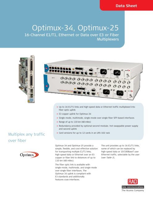
Optimux-34, Optimux-2516-Channel E1/T1, Ethernet or Data over E3 or Fiber MultiplexersData SheetCARD MODULES FOR LRS-102Note: For OP-34C/OP-25C cards operatingin the Megaplex-4100 enclosure, refer toa separate OP-34C/OP-25C data sheetinclu<strong>de</strong>d into the Megaplex-4100 fol<strong>de</strong>r.OP-34C/!/+16-Channel E1, Ethernet or Data over E3or Fiber Multiplexer ModuleOP-25C/!/+16-Channel T1, Ethernet or Data overFiber Multiplexer ModuleLegend! Ethernet port (Default=no Ethernet):ETH 10/100BaseT Ethernetport+ SFP link interface:SFP-12 Electrical coax, SMB(OP-34C only)SFP1 LED, 1310 nm, multimo<strong>de</strong>,LCSFP2 Laser, 1310 nm, singlemo<strong>de</strong>, LCSFP3 Long-haul laser, 1310 nm,single mo<strong>de</strong>, LCSFP4 Long-haul laser, 1550 nm,single mo<strong>de</strong>, LCSFP10a Laser WDM, Tx –1550 nm,Rx –1310 nm, singlemo<strong>de</strong>, single fiber, LC(SF1)SFP10b Laser WDM, Tx –1310 nm,Rx –1550 nm, singlemo<strong>de</strong>, single fiber, LC(SF2)2XSFP12 Dual SFP-12 modules2XSFP1 Dual SFP-1 modules2XSFP2 Dual SFP-2 modules2XSFP3 Dual SFP-3 modules2XSFP4 Dual SFP-4 modules2XSFP10a Dual SFP-10a modules2XSFP10b Dual SFP-10b modulesNote: For single fiber applications, a <strong>de</strong>vicewith SFP-10a interface is always usedopposite a <strong>de</strong>vice with SFP-10b interface, andvice versa.SUPPLIED CARD ACCESSORIESCBL-SMB-BNC/MSMB to BNC adapter cable for OP-34C(supplied with SFP-12)OPTIONAL CARD ACCESSORIESCBL-G703-8/RJ45/ETHSplitter cable for splitting each 44-pin cardconnector to 8 E1 or 8 T1 balanced RJ-45connectors and one Ethernet RJ-45connectorCBL-G703-8/COAX/ETHSplitter cable for splitting each 44-pinOP-34C card connector to 8 pairs ofunbalanced BNC connectors and oneEthernet RJ-45 connectorAll cables are 2m (6.6 ft) long.326-100-09/09 Specifications are subject to change without prior notice. © 1997–2009 RAD Data Communications Ltd. The RAD name, logo, logotype, and the terms EtherAccess, TDMoIP and TDMoIP Driven, and theproduct names Optimux and IPmux, are registered tra<strong>de</strong>marks of RAD Data Communications Ltd. All other tra<strong>de</strong>marks are the property of their respective hol<strong>de</strong>rs.Figure 4. Aggregation and Extension of Co-located 2G/3G Base Stations over Different InfrastuctureInternational Headquarters24 Raoul Wallenberg StreetTel Aviv 69719, IsraelTel. 972-3-6458181Fax 972-3-6498250, 6474436E-mail market@rad.comXORTEC GmbHBerner Strasse 7960437 Frankfurt am MainGermanyNorth America Headquarters900 Corporate DriveMahwah, NJ 07430, USATel. 201-5291100Toll free 1-800-4447234Fax 201-5295777E-mail market@radusa.comwww.rad.com Or<strong>de</strong>r this publication by Catalog No. 803830Phone: +49 69 5069886-0Fax: +49 69 5069886-29E-Mail: home@xortec.<strong>de</strong>ORTECINFORMATION TECHNOLOGY..... for your business!The Access Companywww.XORTEC.<strong>de</strong>