Create successful ePaper yourself
Turn your PDF publications into a flip-book with our unique Google optimized e-Paper software.
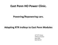
Part 4: Constant-Voltage Lighting SchematicsLight-Emitting DiodesBefore examining complete schematics, let’s look at one more useful device, the light-emitting diode(LED). We have already used diodes as electrical one-way valves and as a convenient source ofconstant voltage drop to operate low-voltage light bulbs. The LED is a more exotic diode whichemits light when it conducts. LED’s are easily and inexpensively available in a variety of sizes, andin red, green or amber colors. The light they provide tends to be very directional, meaning you won’tsee much of it from the side of the LED. (Low-voltage light bulbs work better for lighting models ofold-fashioned marker lanterns with multiple lenses.) An LED’s light level varies only a little as thesupplied voltage varies. LED’s provide light with little or no heat generation, and they last a longtime; these are both advantages in modeling.LED’s are a light and a control diode all in one. When the voltage is reversed, they do not conductand do not light. What could be better for taillights? A resistor is needed in series with an LED tolimit current. A typical LED might handle 20 milliamps (0.020 amps) safely and need about 2 voltsacross it to operate. LED’s differ, so it’s best to calculate the resistance needed in each application.To do this, take the maximum voltage being supplied, and subtract from it the LED’s specifiedvoltage requirement to calculate the voltage left for the resistor to handle. Using Ohm’s Law, dividethis remaining voltage <strong>by</strong> the LED’s current rating to determine the resistance value that is needed.Finally, round the resistance up to the next highest commercially available value. Rounding upwardreduces the current, adding a margin of safety. Not all throttle power supplies stop at 12 volts, so it’sbest to be conservative (high) in choosing your resistance value. Here’s an example: 15 volts maximumsupply minus 2 volts across the LED leaves 13 volts across the resistor. The resistance to passonly 0.020 amperes at 13 volts is 13 divided <strong>by</strong> 0.020, or 650 ohms. Most model railroading articlesadvise a 1000 ohm, half-watt resistor for a typical LED.Constant-Voltage Lighting SchematicsThe classic model trolley wiring schemes, using 12-volt bulbs, have already been presented. Now wecan put together constant-voltage schemes (also called constant brightness or constant intensity).Figure 9 shows a direct wiring scheme and Figure 10 is its pole-reverse counterpart. You shouldrecognize in them the various building blocks we’ve learned about: directional control diodes,voltage-drop diodes, a shunted bridge rectifier, low-voltage light bulbs, and LED’s. Notice that theLED’s happen to be fed from the voltage-dropping diodes and not from the full track voltage. This isan attempt to keep their brightness very constant, and also to reduce unnecessary wattage beingturned into heat <strong>by</strong> their protection resistors.The schematics are very similar. In both, power flows in series through a lighting circuit and thenthrough the motor. The lighting circuit has 2.1 volts total drop. The interior lights use 1.4 volts ofthat total. So do the headlights, since their directional control diodes use up the other 0.7 volts. Theentire 2.1 volts is available to meet the higher voltage needs of the LED taillights.We’re really getting someplace now, but don’t use these schematics with a modern can motor. We’llsee why in a future article.