
Create successful ePaper yourself
Turn your PDF publications into a flip-book with our unique Google optimized e-Paper software.
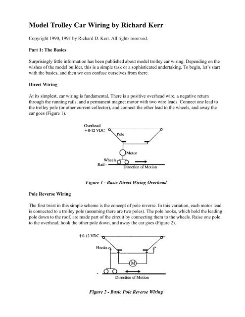
<strong>Model</strong> <strong>Trolley</strong> <strong>Car</strong> <strong>Wiring</strong> <strong>by</strong> <strong>Richard</strong> <strong>Kerr</strong>Copyright 1990, 1991 <strong>by</strong> <strong>Richard</strong> D. <strong>Kerr</strong>. All rights reserved.Part 1: The BasicsSurprisingly little information has been published about model trolley car wiring. Depending on thewishes of the model builder, this is a simple task or a sophisticated undertaking. To begin, let’s startwith the basics, and then we can confuse ourselves from there.Direct <strong>Wiring</strong>At its simplest, car wiring is fundamental. There is a positive overhead wire, a negative returnthrough the running rails, and a permanent magnet motor with two wire leads. Connect one lead tothe trolley pole (or other current collector), and connect the other lead to the wheels, and away thecar goes (Figure 1).Pole Reverse <strong>Wiring</strong>Figure 1 - Basic Direct <strong>Wiring</strong> OverheadThe first twist in this simple scheme is the concept of pole reverse. In this variation, each motor leadis connected to a trolley pole (assuming there are two poles). The pole hooks, which hold the leadingpole down to the roof, are made part of the circuit <strong>by</strong> connecting them to the wheels. Raise one poleto the overhead, hook the other pole down, and away the car goes (Figure 2).Figure 2 - Basic Pole Reverse <strong>Wiring</strong>
Which Method is Better?The answer to this question depends on whom you ask, but let’s look at some particulars so you candecide for yourself. Both arrangements will be shown in subsequent chapters.The advantage of pole reverse wiring is that changing ends (raising one pole and lowering the other)changes which motor lead is positive and which is negative, automatically reversing the car. Insteadof throwing a direction switch on a control panel, the operator is using the trolley poles, thrown inunison, as a double-pole, double-throw switch. The end result is basically the same.If you operate any point-to-point routes with no loops, or a point-to-loop route, direct wiring canmake it difficult to operate and to remember which way different cars are facing. The NMRA standardrequires a car to move “forward” with a positive overhead, but if your car is double ended,which end is forward? This is not just an academic issue. On a large layout or module setup, manycars can be operated simultaneously with one control. Would you like to put your car on the track orstart it up without worrying about which end of your car is “forward”? Would you like to be able torun it with either end forward (for example, baggage or coach end)? Would you like to reverse a carinto a trailing-switch siding or crossover, while all other cars continue forward uninterrupted? Polereverse offers these advantages.Pole reverse wiring has its disadvantages, too. For one thing, the modeller must electrically insulatethe poles, which is sometimes difficult to do on a metal roof (Walthers offers insulated bushings).The pole hooks have to be wired, which may also be difficult on a particular commercial model. Polereverse is hard to engineer on a car with only one pole or with pantographs. Having a mixed fleet ofdirect-wired and pole reverse cars can make operations confusing! Some modelers also argue thatpole reverse wiring involves more wires inside the confines of the carbody than direct wiring, andrequires more connections between the carbody and the roof or floor, whichever is removable formaintenance. These points would appear to be true, based on the two figures shown above. Rememberingthat the motor is usually in a power truck, it looks like three connections are needed (twomotor leads and the ground wire), while the direct-wired car seems to need only one connection. Aswe shall see in a future installment, this is not really the case if you also want operating lights. Withthe lights factored in, the wiring added for pole reversal is minimal. Let’s clear up another misconception,while we’re at it. The pole reverse wiring scheme does not prohibit an operator from backinga car “against the pole.” Just throw that old direction switch on the control panel, the same asalways.Next we will look at more complicated circuits with interior lights, headlights, and taillights. A morepractical wiring diagram method will be introduced. Beyond that, we will drift into relatively new,not classic, wiring methods. We will review the so-called constant voltage lighting, light-emittingdiodes (LED’s), can-style motors, and other subjects.Part 2: The ClassicsOperating Lights (and Diodes)Many modellers add working lights to model trolleys. In the classic method (Figure 3 shows directwiring), 12 volt bulbs are wired in parallel to the motor. They see the same varying voltage that the
A More Practical <strong>Wiring</strong> DiagramSo far this article uses a fairly common style of wiring diagram, drawn to simplify understanding thecircuit. The wiring, when done, will be different. Let’s introduce another way of drawing circuits,showing the actual wiring for a model with a removable floor. Making the floor removable, insteadof the roof, makes it easy to hide the mating seams and fasteners and keeps the wiring for lights inthe roof and ends together. Figures 5 and 6 show the same wiring as Figures 3 and 4, but laid out onthe underside of a car roof. If you prefer removable-roof models, you can draw your own sketches tosuit.Figure 5 - Classic Direct <strong>Wiring</strong> w/LightsOne construction trick is to use stiff brass strip or wire shape (held <strong>by</strong> homemade brass wire staples),instead of electrical wire, along the length of the roof. Then you can solder light bulbs to these buslines at any location. The diagrams show connectors, which simplify disassembly and maintenancelater. They can be real electrical mini-connectors, small dress snaps from the sewing department,tack-soldered wire ends, or the floor fastening screws.Figure 6 - Classic Pole revers w/Lights
The previous section we stated that pole reverse wiring adds only slight complexity in an iiluminatedcar model. Comparing Figure 6 to Figure 5 shows three roof-length bus wires and connectors insteadof two, and the elimination of all four headlight/taillight control diodes.Part 3: Good<strong>by</strong>e Plain <strong>Wiring</strong>, Hello ElectronicsAt this point we have covered the most rudimentary motor wiring, and the enhancements of polereversal and working lights. Even at this level, we managed to sneak in diodes and the concepts ofseries and parallel wiring of electrical components. Now it’s time for a smattering of electricalformulas (in plain English) before we move onward.The following facts will be useful in looking at total circuit designs and in sizing components to beadequate. Components wired in series share the same current and split the power supply voltage.Components wired in parallel share the power supply voltage and their separate current loads add upto the total load on the power supply. Mr. Ohm figured out that voltage equals amperage multiplied<strong>by</strong> resistance. Power wattage is amperage multiplied <strong>by</strong> voltage. For example, a diode used to makea 12 volt headlight operate directionally must handle the current drawn <strong>by</strong> the bulb. A typical grainof wheat bulb draws 0.1 amps at 12 volts. It therefore has a resistance when lit of 12 divided <strong>by</strong> 0.1or 120 ohms, and it consumes 12 times 0.1 or 1.2 watts maximum. A typical 50 volt, 1 amp diode ismore than up to the job, and could easily handle two taillight bulbs wired in parallel, drawing 0.2amps.Another Property of Diodes: Voltage DropWe know that ordinary diodes conduct electricity in one direction only. The atomic properties of thematerials in the diode require a certain voltage across the diode to be reached before the electronsbreak free and flow as electrical current. For older germanium diodes, this voltage was 0.3 volts, andfor today’s silicon diodes it is 0.7 volts. This voltage is “lost” in the diode. If you have 12 volts inyour overhead, a diode-controlled headlight in your model will only get 11.3 volts; at six volts, thelight will only get 5.3 volts. This is no big deal.Figure 7 - Diode DropThe big deal is that the voltage drop across the diode stays at this constant value, regardless of thesupplied voltage going up and down. Some clever modeller years ago saw the diode not asa one-way control valve for electricity, but, in a totally different use of the device, as a source of
constant voltage. Look at Figure 7. Two diodes, each losing 0.7 volts, are placed in series in a modeltrolley’s motor circuit, for a total drop of 1.4 volts. The rest of the supplied voltage goes to the motor.The current drawn <strong>by</strong> the motor is split <strong>by</strong> the diodes and a 1.5 volt bulb placed across the diodes.No matter how much the controller is cranked up, the bulb sees 1.4 volts. As a result, the lightinglevels stay relatively constant, not getting dim and bright with car speed. Micro-sized 1.5 volt bulbsare now commonly available to modellers.However, don’t wire a model like Figure 7! Throwing the control panel reverse switch will make thediodes block the reversed power. The total motor current will then detour through the little 1.5 voltbulb until it goes poof. Notice that the motor in Figure 7 sees a voltage 1.4 volts below what it usedto see. The car will start later and have a lower top speed. This can be an improvement, not a problem.Running cars equipped with commercial power trucks and constant voltage lighting, the authorfinds that the controller voltage he sees for reasonable speeds range at most between 3 and 7 volts.Bridge RectifiersFigure 8(a) shows a usable constant lighting circuit. The two pairs of diodes allow current to flowproperly in both directions. (A single diode in one path would provide a bright/dim light reversal,like many steam locomotives had.) A neater installation than using four separate diodes is to use asingle bridge rectifier package. As Figure 8(b) illustrates, a bridge rectifier is a four-diode setupcommonly used to convert AC power to full-wave DC power. The positive current from a householdelectrical source will switch between the “AC” terminals of the bridge 120 times every second, butwill always be directed to the “ + “ output terminals of the diodes. We are not using the bridge torectify AC power here, just as a handy package of four diodes. By shunting the “+” and the “-”terminals (carefully soldering them together— always use a small, hot iron to quickly solder diodes),we create Figure 8(c), which is equivalent to Figure 8(a). Radio Shack part 276-1161 is a small 50volt, 1 amp bridge rectifier that is just dandy for this application. The lights supplied <strong>by</strong> the shuntedbridge rectifier will come on before the car starts to move. A minimum controller voltage of about 2volts lets the car sit motionless with their lights on.Figure 8 - Constant-Voltage Lighting Circuits.
Part 4: Constant-Voltage Lighting SchematicsLight-Emitting DiodesBefore examining complete schematics, let’s look at one more useful device, the light-emitting diode(LED). We have already used diodes as electrical one-way valves and as a convenient source ofconstant voltage drop to operate low-voltage light bulbs. The LED is a more exotic diode whichemits light when it conducts. LED’s are easily and inexpensively available in a variety of sizes, andin red, green or amber colors. The light they provide tends to be very directional, meaning you won’tsee much of it from the side of the LED. (Low-voltage light bulbs work better for lighting models ofold-fashioned marker lanterns with multiple lenses.) An LED’s light level varies only a little as thesupplied voltage varies. LED’s provide light with little or no heat generation, and they last a longtime; these are both advantages in modeling.LED’s are a light and a control diode all in one. When the voltage is reversed, they do not conductand do not light. What could be better for taillights? A resistor is needed in series with an LED tolimit current. A typical LED might handle 20 milliamps (0.020 amps) safely and need about 2 voltsacross it to operate. LED’s differ, so it’s best to calculate the resistance needed in each application.To do this, take the maximum voltage being supplied, and subtract from it the LED’s specifiedvoltage requirement to calculate the voltage left for the resistor to handle. Using Ohm’s Law, dividethis remaining voltage <strong>by</strong> the LED’s current rating to determine the resistance value that is needed.Finally, round the resistance up to the next highest commercially available value. Rounding upwardreduces the current, adding a margin of safety. Not all throttle power supplies stop at 12 volts, so it’sbest to be conservative (high) in choosing your resistance value. Here’s an example: 15 volts maximumsupply minus 2 volts across the LED leaves 13 volts across the resistor. The resistance to passonly 0.020 amperes at 13 volts is 13 divided <strong>by</strong> 0.020, or 650 ohms. Most model railroading articlesadvise a 1000 ohm, half-watt resistor for a typical LED.Constant-Voltage Lighting SchematicsThe classic model trolley wiring schemes, using 12-volt bulbs, have already been presented. Now wecan put together constant-voltage schemes (also called constant brightness or constant intensity).Figure 9 shows a direct wiring scheme and Figure 10 is its pole-reverse counterpart. You shouldrecognize in them the various building blocks we’ve learned about: directional control diodes,voltage-drop diodes, a shunted bridge rectifier, low-voltage light bulbs, and LED’s. Notice that theLED’s happen to be fed from the voltage-dropping diodes and not from the full track voltage. This isan attempt to keep their brightness very constant, and also to reduce unnecessary wattage beingturned into heat <strong>by</strong> their protection resistors.The schematics are very similar. In both, power flows in series through a lighting circuit and thenthrough the motor. The lighting circuit has 2.1 volts total drop. The interior lights use 1.4 volts ofthat total. So do the headlights, since their directional control diodes use up the other 0.7 volts. Theentire 2.1 volts is available to meet the higher voltage needs of the LED taillights.We’re really getting someplace now, but don’t use these schematics with a modern can motor. We’llsee why in a future article.
Figure 9 - Constant Lighting - Direct <strong>Wiring</strong>Figure 10 - Constant Lighting - Pole ReverseFuture Articles: Can motors and Fred Weigle’s schematic, followed <strong>by</strong> a review of different lightingmethods.Copyright 1991 <strong>by</strong> <strong>Richard</strong> D. <strong>Kerr</strong>. All rights reserved.