auroSTOR installation.pdf - Vaillant Export
auroSTOR installation.pdf - Vaillant Export
auroSTOR installation.pdf - Vaillant Export

Create successful ePaper yourself
Turn your PDF publications into a flip-book with our unique Google optimized e-Paper software.
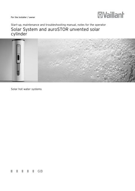
Notes on the documentation 1Overview of standards, safety instructions 21 Notes on the documentationYour solar system is a quality product from <strong>Vaillant</strong>.This manual describes the entire system, all of itscomponents and the cylinder and provides you withinformation on start-up, maintenance and troubleshooting.It is a supplement to the operating, <strong>installation</strong>and assembly manuals of the individual components.Observe the manuals for each individual systemcomponent in conjunction with this manual.Look after this manual and pass it on to the next owner.h Note!The “Start-up” and “Maintenance andtroubleshooting” chapters of this manual areintended only for approved specialists.<strong>Vaillant</strong> accepts no liability for any damage caused byfailure to observe this manual.Other applicable documents- Assembly manual of the collectors- Operating and <strong>installation</strong> manual of the controller- Operating and <strong>installation</strong> manual of the boiler (ifused)- Assembly, operating and <strong>installation</strong> manuals of allaccessories used- Warranty cardSymbols usedPlease observe the safety instructions in this manualwhen operating and installing the solar system and the<strong>auroSTOR</strong> solar cylinder.The symbols used in the manual are explainedbelow:d Danger!Immediate risk of serious injury or death!e Danger!Danger of death from electric shock!e Danger!Risk of burns or scalding!a Caution!Potentially dangerous situation for the productand environment.h Note!Application recommendation.• Symbol for a required task2 Overview of standards,safety instructions2.1 Overview of EU standardsSolar system in generalEN ISO 9488Thermal solar system and components, terminology(ISO/DIS 9488; 1995)EN 12975-1Thermal solar systems and components; Collectors, Part1: General requirementsEN 12975-2Thermal solar systems and components; Collectors; Part2: Test methodsENV 1991-2-3Eurocode 1 – Basis of design and actions on structures,Part 2–3: Actions on structures - Snow loadsEN 12976-1Thermal solar systems and components;Factory made systems - Part 1: General requirementsEN 12976-2Thermal solar systems and components;Factory made systems - Part 2: Testing methodsENV 12977-1Thermal solar systems and components;Custom built systems,Part 1: General requirementsENV 12977-2Thermal solar systems and components;Factory made systems,Part 2: Testing methodsISO 9459-1: 1993Solar heating – Domestic water heating systems – Part 1:Performance rating procedure using indoor testmethodsISO/TR 10217Solar energy – Water heating systems – Guide tomaterial selection with regard to internal corrosionCollectors and collector assemblyENV 1991-2-4Eurocode 1 – Basis of design and actions on structures -Part 2–4: Actions on structures - Wind actionsManual - Solar hot water systems3
3 System description6789CDDHW23M410111AB5MFig. 3.1 System for solar heating of drinking waterKey1 Boiler2 <strong>auroSTOR</strong> solar cylinder3 230 V∼motorised 2 port valve (supplied together with the solarcylinder)4 Immersion heater5 230 V∼ motorised 2 port valve (supplied together with theboiler)6 auroTHERM collector7 Solar pump unit8 Protection vessel (optional)9 Solar expansion vessel10 Automatic air separator system11 Drinking water expansion vesselA Boiler flowB Boiler returnC Solar circuit flowD Solar circuit return6Manual - Solar hot water systems
4 Description of the components4 Description of the components4.1 CollectorsH Danger!Risk of burns!To avoid injuries due to hot parts of thecollectors, all work on the collectors should becarried out on cloudy days. Alternatively workcan be carried out in the morning or evening ofsunny days or with the collector covered.4.1.1 auroTHERM exclusive tube collectorInterior designThe <strong>Vaillant</strong> auroTHERM exclusive VTK 275 and 550tube collectors consist of 8 or 16 collector tubesconnected in parallel. With its collector tubes withinternal mirror of pure silver and glass-glass connectionof sleeve and absorber pipe for lasting vacuum sealing,the collector ensures constant high performance over itsentire service life. The high-performance absorber has aCermet Aluxid ® vacuum coating. Extremely low heatlosses of k 1= 0.68 W/(m 2 K) thanks to a high vacuum of< 10 -6 bar ensure year-round use.By deliberately interrupting heat transfer to thedownstream system, the auroTHERM exclusive provideseffective system protection against excess temperaturesabove 180 °C if the system is shut down.The collectors are connected in series.1 26534Fig. 4.1 auroTHERM exclusive VTK 550 tube collectorFig. 4.3 Cross-section through four tubes with direction of flowKey1 Outer collector tube2 Inner collector tube3 Guide tube4 Absorber tube5 Outlet6 InletFig. 4.2 auroTHERM exclusive VTK 275 tube collector8Manual - Solar hot water systems
Description of the components 4Technical data of the tube collectorsAppliance designation Units auroTHERM exclusive VTK275auroTHERM exclusive VTK550Surface area (gross, aperture/net) m 2 0.68 / 0.41 1.28 / 0.82Height mm 1695 1695Width mm 440 790Depth mm 100 100Weight kg 10.3 20Collector capacity l 1.6 3.56Copper pipe connection, flat-face Thread 3/4“ 3/4“Insulation: high vacuum bar 10 -6 10 -6Maximum operating pressure bar 6 6Pure silver mirror, degree of reflection ρ % 94 ± 1 94 ± 1Absorber emission ε % 5 ± 2 5 ± 2Absorber absorption α % 95 ± 1.0 95 ± 1.0Solar sensor sleeve ∅ mm 6 6CE label 0036 0036Shutdown temperature (according to prEN 12975-2, °C 250 250c < 1 m/s) in the glass tubeShutdown temperature (according to prEN 12975-2, °C 180 180c < 1 m/s) at the collector connectionEfficiency η 0(according to EN 12975) % 78 ± 3% 78 ± 3%Efficiency coefficient k 1W/(m 2 •K) 1.09 ± 0.2 1.09 ± 0.2Efficiency coefficient k 2W/(m 2 •K 2 ) 0.01 ± 0.002 0.01 ± 0.002Table 4.1 Technical data tube collector auroTHERM exclusive[%] 1,00,9400,80,70,60,50,40,3Pressure loss [mbar]3020auroTHERMexclusive0,2100,10 0 20 40 60 80 100 120 140 160 180 200 220 2401000 W/m 2 Insolation Temperature difference (collektor/ambient) [K]800 W/m 2 Insolation auroTHERM exclusive300 W/m 2 Insolation00 50100 150 200 250 300Volume flow [l/h]Fig. 4.4 Efficiency of the auroTHERM exclusive according toDIN 4757/4Fig. 4.5 Pressure loss of the auroTHERM exclusive collectorManual - Solar hot water systems9
Description of the components 44.1.3 DisposalAll <strong>Vaillant</strong> solar collectors meet the requirements forthe German “Blauer Engel” (Blue Angel) environmentalmark.Therefore, we, as the manufacturer, will take back andrecycle components when they have to be disposed ofafter years of reliable use.- Two fill/vent valves for filling and draining the solarcircuit (6 and 9)- A three-speed solar pump (8)- A flow rate meter to optimally adjust the required flowrate (7)- A solar expansion vessel (4) (separate accessory)- A protection vessel (5) (separate accessory)4.2 Solar pump unit111098124.2.2 Water control packThe solar pump unit is delivered with a water controlpack, consisting of an expansion relief valve (1) and apressure gauge (2) for visual inspections.4.2.3 Solar expansion vesselThe solar expansion vessel (4), is used to equalise thepressure while the pressure relief valve (1) blows off thesolar fluid into the collecting container via the pressurerelease pipe (3) if the operating pressure of 6 bar isexceeded.5476Fig. 4.9 Design of the solar pump unitKey1 Expansion relief valve2 Pressure gauge3 Pressure release pipe with collecting container4 Solar expansion vessel5 Protection vessel (optional)6 Fill/vent valve (for filling and draining the solar circuit)7 Flow rate meter8 Three-speed solar pump9 Fill/vent valve (for filling the solar circuit)10 Group of pipes with insulation11 Stop valves with gravity brakes4.2.1 DesignThe solar pump unit transports heat from the collectorto the consumer safely and efficiently.The solar pump unit mainly consists of:- The group of pipes of the solar pump unit withinsulation (10)- Two stop valves with gravity brakes (11) to preventheat diversion. (The gravity brakes are ineffective ifthe stop valves are in the 45° position.)- The water control pack with an expansion relief valve(1) with 6 bar blow-off pressure and a pressure gauge(2) for visual inspection3h Note!The solar fluid container is of sufficient sizeand intended as a collecting container. Lay apressure release pipe from the expansion reliefvalve to the collecting container.The size of the solar expansion vessel is based on thecollector volume and the expansion volume of the solarsystem.The expansion vessel not only accommodates theexpansion volume of the solar fluid, but also the entirevolume of the collectors in the event of a shutdown. Thetotal volume of the solar system is the total of theindividual values of the collector, heat exchanger volumeand the volume of the pipeline.The admission pressure of the solar expansion vesselcan be set between 0.5 and 4.0 bar.4.2.4 Protection vessel (item no. 302 405)In the event of unfavourable system configurations (e. g.very large collector surface, <strong>installation</strong> of the solarpump unit under roof), the solar expansion vessel (4)may be subjected to excessive temperatures by the solarfluid if the system is shut down. In worst cases, this cancause the membrane of the solar expansion vessel to beoverheated and to fail.The <strong>installation</strong> of a protection vessel (5) isrecommended in all cases. The solar expansion vessel isprotected from excessive temperatures by 5 l of solarfluid in front of it. <strong>Vaillant</strong> recommends the <strong>installation</strong>of the protection vessel for all solar systems (itemno. 302 405).Manual - Solar hot water systems11
4 Description of the components4.3 Solar pumpThe solar pump unit is equipped with a three-speed solarpump (Fig. 4.9, pos. 8) for the optimum adaptation ofthe required circulating volume and the pump capacityin the solar circuit.Select the pump capacity, depending on the solar system(e. g. collector surface, pipe diameter, length of the solarcircuit), so that the actual flow rate is slightly higherthan the nominal flow rate. The flow rate meter (Fig. 4.9,pos. 7) is used for fine adjustment of the flow rate.Observe the notes in Section 6.2, Setting the flow rateand pump.4.4 Thermal cut out of the solar pump4.5 Flow rate meterL/minL/min6544563322110,50,51,1 l/min1213ABCD33ABCDFig. 4.11 Flow rate meter 0 - 6 l/minThe flow rate meter (pos. 7, Fig. 4.6) installed in thereturn pipe is an essential component of the solarsystem. To achieve optimum heat transfer, you mustachieve a certain flow rate, which is referred to as thenominal flow rate (refer to Section 6.2, Setting the flowrate and pump).Upper deviations are not as serious as lower deviations.Make the rough adjustments with the solar pump first.You can make the fine adjustments with the adjustmentvalve (1) of the flow rate meter. You can view the setvalue on the display (2) of the flow rate meter.The flow rate meter has a fill/vent valve for filling anddraining the solar circuit.Fig. 4.10 Connection diagram of the solar pump TCOThe solar pump is secured by its own thermal cut out(TCO) (1) which is mounted on the solar cylinder (preassembledat the factory for the VIH S GB 250 and300 S). The power supply to the pump is interrupted atcylinder temperatures higher than 90 °C.h NoteDo not under any circumstances set the flowrate below the calculated flow rate. Thecollector efficiency will be considerably reduced.4.6 Solar fluid4.6.1 Properties of the solar fluidThis information applies to <strong>Vaillant</strong> solar fluid (20 lcanister: item no. 302 429).<strong>Vaillant</strong> solar fluid is a ready-mixed antifreeze andanticorrosive, consisting of approximately 45%propylene glycol with anti-corrosion inhibitors and 55%water. It is resistant to high temperatures and can beused both with <strong>Vaillant</strong> tube collectors and <strong>Vaillant</strong> flatplate collectors.Furthermore the solar fluid has a high thermal capacity.The inhibitors provide reliable corrosion preventionwhen using different types of metal (mixed <strong>installation</strong>s).12Manual - Solar hot water systems
Description of the components 4h Note!Do not use any other anti-freeze or inhibitorswith <strong>Vaillant</strong> solar collectors.Only <strong>Vaillant</strong> solar fluid is approved.a Caution!Risk of damage!<strong>Vaillant</strong> solar fluid is ready mixed. You may notunder any circumstances mix it with water orother fluids. Otherwise it will becomeineffective as an antifreeze or anticorrosive,resulting in damage to collectors or other partsof the system.<strong>Vaillant</strong> solar fluid is infinitely durable in hermeticallysealed containers.Skin contact is normally not dangerous. Eye contact onlycauses minor irritations, you should neverthelessimmediately wash your eyes.Observe the safety data sheet (refer to Section 4.6.4).Proceed as follows to check the solar fluid; refer to theoperating manual of the solar fluid tester (item no.002 002 0155):• Suck in the amount of fluid for the float to freely floatwithout sticking at the top with the suction ball of thesolar fluid tester (item no. 00 2002 0645).• View the density on the scale. The density must begreater than 1.05 g/cm 3 . You must otherwise replacethe solar fluid.• Measure the pH value with a pH value measuring strip.You must replace the solar fluid if the pH value isbelow 7.5.1234.6.2 Protection of the solar circuit against frostand corrosionTo protect the solar system reliably against frost inwinter, the entire solar circuit must be filled 100 % withsolar fluid (item no. 302 429).h Note!You can achieve frost resistance of about-28 °C by filling the solar system with <strong>Vaillant</strong>solar fluid.No damage is caused by frost even at outsidetemperatures below -28 °C, since the expansiveeffect of the water is reduced. Check theantifreeze effect after filling the system andthen once a year.6Fig. 4.12 Solar fluid testerKey1 Transport case2 Areometer3 Thermometer4 pH indicator rod5 Standing cylinder6 Operating manual45ComponentVolume (l)VIH S GB 200 S heat exchanger solar circuit 4.12VIH S GB 250 S heat exchanger solar circuit 4.12VIH S GB 300 S heat exchanger solar circuit 4.4VIH S GB 200 S heat exchanger reheating circuit 3.7VIH S GB 250 S heat exchanger reheating circuit 3.7VIH S GB 300 S heat exchanger reheating circuit 3.7Solar pump unit 0.9auroTHERM exclusive VTK 550 3.56auroTHERM exclusive VTK 275 1.6auroTHERM VFK 900 1.1Protection vessel 5.0Table 4.3 Volume of the individual componentsa Caution!Risk of damage!Use only the original <strong>Vaillant</strong> solar fluid tester(item no. 00 2002 0645). Otherwise anincorrect antifreeze value may be indicated.4.6.3 Frost protection of the bivalent solar cylinderYou must drain the solar cylinder completely if it is to beshut down in a room prone to frost. It is drained at thecold water inlet with a T-piece with tap to be provided bythe installer.• Also drain all heat exchangers which are not filled withsolar fluid.Pipe diameterPipeline volume (l/m)15 mm 0.1818 mm 0.2022 mm 0.3128 mm 0.50Table 4.4 Pipeline volumeManual - Solar hot water systems13
4 Description of the components4.6.4 Safety data sheet1. Substance/Formulation and company name1.1 Information on the product:Trade name of the <strong>Vaillant</strong> solar fluid(item no. 302 362)1.2 Information on the supplier: <strong>Vaillant</strong>GmbH, Berghauser Str. 40,42859 Remscheid, GermanyTelephone +49 (02191) 18 - 0,fax +49 (02191) 182810,Emergency information: your local poisoninformation centre(see directory assistance or telephone directory).2. Composition/Information on components2.1 Chemical propertiesWatery solution of 1.2 propylene glycol withcorrosion inhibitors3. Possible risks3.1 No particular risks known4. First-aid measures4.1 General notes:Remove dirty clothes.4.2 After inhaling:Discomfort after inhaling fumes/aerosol: fresh air, help from a doctor.4.3 After skin contact:Wash off with water and soap.4.4 After eye contact:Wash thoroughly under running water with wideopen eyes for at least 15 minutes.4.5 After swallowing:Rinse your mouth and then drink plenty of water.4.6 Notes for the doctor:Treatment of symptoms (decontamination,vital function), no specific antidote known.5. Firefighting measures5.1 Appropriate extinguishing agents:Spray, solid extinguishing agent, alcohol-fastfoam, carbon dioxide (CO 2)5.2 Particular hazards:Fumes which are detrimental to health. Formationof smoke/mist. The specified substances/substance groups may be released in the event ofa fire.5.3 Special protective equipment for fire fighting:Wear a breathing apparatus which is independentof the circulating air in the event of a fire.5.4 Further details:The hazard depends on the combustiblesubstances and the fire conditions. Polluted firewater must be disposed of according to localofficial regulations.6. Measures to be taken if substances arereleased accidentally6.1 Individual-related measures:No particular measures required.6.2 Environmental measures:The product may not be discharged into waterswithout pre-treatment (biological sewage plant).6.3 Cleaning/Collection methods:Pump out the product in the event of largequantities.Absorb small quantities with appropriate fluidbonding material. Then dispose of them accordingto regulations.Rinse away splashes with plenty of water. Informthe local water authority in the event of largequantities which could flow into the drainage orwaters.7. Handling and storage7.1 Handling:Good ventilation of the workplace, no otherparticular measures required.7.2 Fire and explosion protection:No exceptional measures required.Cool any endangered containers with water.7.3 Storage:Close containers tightly and store them at dryplaces. Do not use any galvanised containers forstorage.8. Limitation of exposure and personal protectiveequipment8.1 Personal protective gear:Hand protection: chemical-resistant protectivegloves (EN 374). Suitable materials even in theevent of prolonged, direct contact (recommended:protection index 6, corresponding to > 480minutes permeation time according to EN 374):flour elastomer (FKM) – 0.7 mm layer thickness.Suitable materials for brief contact or splashes(recommended: at least protection index 2,corresponding to > 30 minutes permeation timeaccording to EN 374): nitrile rubber (NBR) – 0.4mm layer thickness. Due to the large variety oftypes, observe the instruction manuals of themanufacturer.8.2 Eye protection:Safety glasses with lateral protection (framedglasses) (EN 166)8.3 General safety and hygiene measures:Observe the usual protective measures fordealing with chemicals.14Manual - Solar hot water systems
Description of the components 49. Physical and chemical propertiesForm: fluidColour: violetOdour: product-specificSolidification temperature: approx. -28 °C(DIN 51583)Boiling temperature: > 100 °C (ASTM D 1120)Flash point: noneLower explosion limit: 2.6 % by vol. (details forUpper explosion limit: 12.6 % by vol. 1.2 propyleneglycol)Ignition temperature: omittedvapour pressure (20 °C): 20 mbarDensity (20 °C): approx. 1.030 g/cm3 (DIN 51757)Water solubility: entirely solubleSolubility (qualitative) solvent: polar solvents:solublepH value (20 °C): 9.0 – 10.5 (ASTM D 1287)Viscosity, kinematic (20 °C): approx. 5.0 mm2/s(DIN 51562)10. Stability and reactivity10.1 Substances to be avoided: Strong oxidants10.2 Dangerous reactions:No dangerous reactions if the storage andhandling regulations/notes are observed10.3 Dangerous decomposition products:No dangerous decomposition products if thestorage and handling regulations/notes areobserved.11. Toxicological information11.1 Acute toxicity:LD50/oral/rat: > 2000 mg/kgPrimary skin irritation/rabbit: not irritating.(OECD guideline 404)Primary irritation to the mucous membrane/rabbit: not irritating.(OECD guideline 405)11.2 Additional notes:The product has not been checked. Thestatements have been taken from the individualcomponents.12. Ecological information12.1 Ecological toxicity:Fish toxicity: LC50 leuciscus idus (96 h):> 100 mg/lAquatic invertebrates: EC50 (48 h): > 100 mg/lWater plants: EC50 (72 h): > 100 mg/lMicro-organisms/effect on activated sludge:DEV-L2 > 1000 mg/l. No disturbances to thebiodegrading activity of the activated sludge areexpected in adapted biological sewage plants ifdischarged appropriately in low concentrations.12.2 Assessment of aquamatic toxicity:The product has not been checked. Thestatements have been taken from the propertiesof the individual components.12.3 Persistence and biodegradability/information onelimination:OECD 301 A test method (new version)Analysis method: DOC acceptanceDegree of elimination > 70 % (28 d)Assessment: easily biodegradable.13. Note on disposal13.1 Disposal:<strong>Vaillant</strong> solar fluid (item no. 302 363) must dedisposed of at an appropriate waste site or wasteincineration plant, for example, while observinglocal regulations. Contact the local municipalsanitation office or the mobile environmentalservice for quantities under 100 l.13.2 Uncleaned packings:Uncontaminated packings can be reused. Disposeof packings which are unable to be cleanedtogether with the substance.14. Transport information:VbF: not subject to the ordinance on combustiblefluids.Mailing permitted. GGVE/RID: -, UN no.: -,GGVS/ADR: -, IATA DGR: -, IMDG code: -, TA air: -.No dangerous goods according to transportregulations.15. Regulations15.1 Labelling in accordance with EC directives/national regulations:No labellingobligation15.2 Other regulations: water hazard class (Germany,Appendix 4 of the VwVwS (administrativeregulation on water-pollutant substances) from17.05.1999): (1), slightly water-pollutant16. Other informationThe safety data sheet is intended to provideessential physical, safety-related, toxicological andecological data and give recommendations forsafe handling or safe storage, handling and safetransport of chemical substances andformulations. No liability is assumed for damagein connection with the usage of this informationor the usage, application, adaptation orprocessing of the products described here. Thisdoes not apply as long as we, our statutoryagents or assistants are liable in the event ofintention or gross negligence. No liability isassumed for indirect damage.This information has been compiled to the best ofour knowledge and conscience according to ourcurrent state of knowledge.No guarantee can be made for product properties.17. VersionCompiled by <strong>Vaillant</strong> GmbH on 1/7/2003Manual - Solar hot water systems15
4 Description of the components4.7 <strong>auroSTOR</strong> solar cylinderThe <strong>auroSTOR</strong> solar cylinder is described in detail inSection 5.1, Installation of the solar cylinder, of thismanual.4.8 Solar control6C5Kol 1Solar gainD4230 V~3 ASp 1Sp 2B12Control of the hot water temperatureThe hot water temperature in the top half of the cylindercan be controlled by the <strong>Vaillant</strong> auroMATIC VRS 560solar control or by using a separate hot waterprogrammer (refer to Section 5.8, Electrical <strong>installation</strong>).WiringThe <strong>Vaillant</strong> Control Center VR 65 can be used to wireup the system if an eBUS-capable <strong>Vaillant</strong> boiler is used.A standard wiring box can be used for all other boilers.Solar pump controlTemperature differences, not absolute temperaturevalues, are important for the operation of solar systems.That is why solar systems are controlled by what isreferred to as temperature difference controllers.Temperature sensors measure the difference betweenthe collector and solar cylinder.The solar pump is switched on if the difference intemperature (Kol 1 - Sp 2) is greater than 7 K. The solarpump of the solar system is switched off if the differencein temperature (Kol 1 - Sp 2) is lower than 3 K.Furthermore the solar control constantly measures thecylinder temperature. Reheating is switched on if thevalue (Sp 1) falls below the set target value.You can set the difference in temperature on thecontroller between 2 and 15 K. The default setting of 7 Kis sufficient for most solar systems.Do not set temperature differences too low. This wouldresult in a number of unnecessary and uneconomicswitch-on and switch-off procedures.auroMATIC 560 controllerFig. 4.13 Temperature difference controlKey1 Solar control2 Boiler3 Solar cylinder4 Thermal cut out of the solar pump5 Solar pump6 Solar pump unitKol 1 Collector temperature sensorSp 1 Upper stored water temperature sensor(reheating circuit/standby part)Sp 2 Lower stored water temperature sensor (solar circuit)A Boiler flowB Boiler returnC Solar flowD Solar returnType of solar controlThe <strong>Vaillant</strong> solar system enables various systemconfigurations and control concepts.Fig. 4.14 auroMATIC 560The auroMATIC 560 solar control is a differentialtemperature-controlled control set for solar-supportedhot water supply with a demand driven reheatingfunction for <strong>Vaillant</strong> boilers.The control set is a fully-equipped system for solarsystems with a collector array and a solar cylinder.It is possible to determine the solar gain by means of anadditional gain sensor (available as an accessory).16Manual - Solar hot water systems
Description of the components 4Installation 5Control Center VR 65The Control Center VR 65 provides a system solutionwhich allows <strong>Vaillant</strong> low-voltage eBUS controllers to beused in the English market with valves and hot watercylinders with traditional 230 V cylinder thermostats.The information on the heat requirements of the solarcylinder is forwarded to the <strong>Vaillant</strong> ecoTEC boiler bythe Control Center VR 65. The boiler decides whetherhot water requirements has to be met and sends thesignal to control the 230 V valves via the VR 65.In this way, the boiler can store different targettemperatures for heating and hot water operation.Standard 230 V components can be integrated in the<strong>Vaillant</strong> eBUS system via the Control Center VR 65. Forwiring, refer to Section 5.8, Electrical <strong>installation</strong>, andthe <strong>installation</strong> manual of the Control Center VR 65(item no. 00 2000 7476).VRT 360 programmable room thermostatThe VRT 360 is a programmable room thermostat with aweek programme for heating, hot water and circulationpump, which can be connected to <strong>Vaillant</strong> boilers withWith the VRT 360, you can preset the room temperaturewith a heating programme.The VRT 360 has additional functions including centralheating override and the time control function of anadditional circulation pump.For wiring, refer to Section 5.8, Electrical <strong>installation</strong>,and the operating and <strong>installation</strong> manual of theVRT 360 (item no. 838 568).5 Installation• Use the following tables to check the scope of deliverybefore beginning with the <strong>installation</strong>.Installation sequenceInstall the solar system in the following order:- Solar collectors and solar pump unit- Solar cylinder- Solar circuit piping- Reheating circuit piping- Hot water piping and secondary return (if available)- Cold water supply- Discharge pipe- Electrical <strong>installation</strong>• Assemble the collectors according to the assemblymanual (item no. 835 254)• Install the solar pump unit according to the <strong>installation</strong>manual (item no. 00 2000 7485)• Proceed with the <strong>installation</strong> as described in thefollowing sections.h Note!If the VRT 360 is used for central heatingcontrol, the Control Center VR 65 isadditionally required to measure the solarcylinder temperature and switch from cylinderreheating to heating mode and vice versa asrequired.VRC 400 weather compensatorThe VRC 400 weather compensator is an externaltemperature compensator and can be used inconjunction with a <strong>Vaillant</strong> eBus boiler to provide timeand temperature control of the central heating.Manual - Solar hot water systems17
5 InstallationSolar sets auroTHERM exclusive Mini Standard Medium LargeItem no. 0020025413 0020025414 0020025415 0020025416auroTHERM exclusive 550 2 3 4 5auroTHERM exclusive 275 1 - - -Mounting bar (long) for 2 x VTK 550 1 1 2 2Mounting bar (normal) for 1 x VTK 550 - 1 - 1Mounting bar (short) for 1 x VTK 275 1 - - -Roof bracket set for 2 x VTK 550 1 1 2 2Roof bracket set for 1 x VTK 550 or 1 x VTK 275 1 1 - 1Rafter plate 2 2 2 3Connection set for collector area 1 1 1 1Single insulated stainless steel tube, DN16, 15 m 2 2 2 2Table 5.1 Scope of delivery of the auroTHERM exclusive solar sets18Manual - Solar hot water systems
Installation 5Solar sets auroTHERM exclusive Mini Standard Medium LargeItem no. 0020025413 0020025414 0020025415 0020025416Fittings pack for DN16 tube 1 1 1 1Solar pump unit 1 1 1 1Expansion vessel 25 l 1 1 - -Expansion vessel 35 l - - 1 1Protection vessel for expansion vessel 1 1 1 1Automatic air separator 1 1 1 1Thermostat mixer 1 1 1 1Solar control auroMATIC 560 1 1 1 1Solar gain sensor (VR 10) 1 1 1 1Solar fluid (20 litres) 2 2 3 3Table 5.1 Scope of delivery of the auroTHERM exclusive solarsets (continuation)Manual - Solar hot water systems19
5 InstallationSolar set auroTHERM flat plate collectorItem no. 0020036552auroTHERM VFK 900 2Roof bracket set for concrete tiles (qty 6) 1On-roof kit for two panels 1Stainless steel connection pipe DN12 2x1m 1Single insulated tube, DN16, length 15m 2Fittings pack for DN16 tube 1Solar pump unit 1Expansion vessel 18 litres 1Protection vessel 1Automatic air separator 1Table 5.2 Scope of delivery the auroTHERM flat plate collectorsolar set20Manual - Solar hot water systems
Installation 5auroTHERM flat plate collector solar setItem no. 0020036552Thermostatic mixing valve 1Solar control auroMATIC 560 1NTC sensor VR10 (solar gain) 1Solar fluid (20 litre) 2Table 5.2 Scope of delivery of the auroTHERM flat platecollector solar set (continuation)Manual - Solar hot water systems21
AB5 Installation<strong>auroSTOR</strong> solar cylindersVIH S GB 200 S VIH S GB 250 S VIH S GB 300 SItem no. 307 206 307 207 307 208Cold water control pack with tundish 1 1 1Motorised 2 port valve1 1 1DHW expansion vessel 18 l 1 - -DHW expansion vessel 25 l - 1 1Mounting bracket for expansion vessel 1 1 1Carrier handle 1 1 1Compression fittings 1 1 1Drain valve 1 1 1Thermal cut out-box for solar pump (holder, cable, capillarytube)pre-assembled pre-assembled pre-assembledTable 5.3 Scope of delivery <strong>auroSTOR</strong>22Manual - Solar hot water systems
Installation 55.1 Installation of the solar cylinder5.1.1 Description of the solar cylinder1192324LNimmersionheaterC°cylindercontrolC°32120211823622174571689151014131112Fig. 5.1 <strong>auroSTOR</strong> function elementsKey1 Hot water connection2 Temperature and pressure relief valve (95 °C, 7 bar)3 Expansion vessel4 Connection for expansion vessel5 Pressure-controlled cold water outlet6 Connection for secondary return7 Cold water supply8 Pressure limiting valve (3.5 bar) with line strainer9 Expansion relief valve (one port valve, 6.0 bar)10 Tundish11 Cylinder drain valve12 Sp 2 temperature sensor immersion sleeve13 Adjustable feet14 Return (solar circuit)15 Flow (solar circuit)16 Return (boiler)17 Flow (boiler)18 Immersion heater switch19 Thermal cut out of solar pump, set to 90 °C, connected to thesolar pump in order to isolate this heat source in the event offailure of the solar control.20 Thermal cut out of immersion heater21 Cylinder thermostat (20 °C - 65 °C)22 Immersion heater23 Thermal cut out of the cylinder thermostat, set to 90 °C,connected to the motorised 2 port valve, in order to isolate theprimary heat source in the event of failure of the domestic hotwater thermostat.24 Thermostat, immersion heaterManual - Solar hot water systems23
5 Installation<strong>auroSTOR</strong> solar cylinders are available in three sizes:200, 250 and 300 litres. The containers are made ofstainless steel and insulated with EPS.The cylinders areequipped with all necessary cold and hot water controldevices and a motorised 2 port valve.The <strong>auroSTOR</strong> cylinders are operated at the pressure ofthe water supply pipe and do not need a cold water tankfor their supply. They have hot and cold waterconnections of 22 mm diameter.A cold water supply ofappropriate pressure and flow rate is required to operatethe solar cylinder ideally (refer to Section 5.6.1, Coldwater supply pressure).VIH S GB 250 S and VIH S GB 300 SThe thermal cut out and temperature sensor have beenpre-installed by the manufacturer.Control of the hot water temperatureThe hot water temperature in the top half of the cylindercan be optionally regulated by the <strong>Vaillant</strong> auroMATICVRS 560 solar control by means of the programmable<strong>Vaillant</strong> VRT 360 room thermostat or a timer.The temperature settings for solar water heating andthe maximum cylinder temperature are made by meansof this solar control, e. g. auroMATIC VRS 560. The<strong>auroSTOR</strong> must be wired properly in order to adhere tothe G3 building regulations.The solar pump must be connected to the solar controlvia a thermal cut out (TCO) (refer to Section 5.8,Electrical <strong>installation</strong>). It ensures the solar pump isswitched off if the hot water temperature in the cylinderrises above 90°C.Fig. 5.3 NTC capillary tube guideA VR 10 temperature sensor (1) must be used instead ofthe installed thermostat if the auroMATIC VRS 560 isused (refer to Section 5.8.2, Electrical connection to thecylinder control device, for the removal of thethermostat).1Immersion heaterThe <strong>auroSTOR</strong> solar cylinders are equipped with anadditional immersion heater of 3 kW, including theoperating thermostat and energy cut-off device.Theimmersion heater is situated behind the front plate. It isdesigned for use in unvented cylinders and includes athermostat control and thermal cut out for over heatprotection.Note:In the event of a replacement, only the rightimmersion heater equipped with a thermal cutout fur overheating protection may be used.Fig. 5.2 Attachment of the solar pump TCOSecondary returnThe water control pack has a connection for a secondaryreturn.• Remove the 3/4“ dummy plug (BSP thread) from thewater control pack.• Connect a WRAS-approved circulating pump, whichcontains a non-return valve, to the water control pack(see Fig. 5.1).• Establish the connection to the secondary return.24Manual - Solar hot water systems
Installation 55.1.2 Technical data of the <strong>auroSTOR</strong> solar cylinderEntry Unit VIH S GB 200 S VIH S GB 250 S VIH S GB 300 SCylinder:Size l 200 250 300Maximum water supply pressure bar 10Operating pressure bar 3.5Pressure limiting valve bar 3.5Expansion relief valve bar 6.0Hot water expansion vessel admission pressure bar 4.0Temperature and pressure relief valve °C/bar 95 / 7.0Net weight kg 39 44 49Weight (full) kg 245 310 340Height mm 1499 1789 2109Cylinder connections:Cold water supply22 mm pressure pipeHot water connection22 mm pressure pipePressure-controlled cold water outlet22 mm pressure pipeSecondary return Inches G 3/4Flow (boiler/solar circuit)22 mm pressure pipeReturn (boiler/solar circuit)22 mm pressure pipeElectrical connections:3 kW immersion heater (according to ENBS 60335) 230/240 V, 50 HzLength of the immersion heater mm 430Motorised 2 port valve230/240 V, 50 HzCylinder thermostat230/240 V, 50 HzThermal cut out for solar pump230/240 V, 50 HzHeating coil:Heat loss kW/24 h 1.9 2.1 2.4Heat up time (boiler part) mins 21 26 30Recovery (boiler part) mins 13 16 21Table 5.4 Technical data of the <strong>auroSTOR</strong> solar cylinderh Note!The heat-up time is based on a primary flowrate of 9 l/min at 80 °C.Temperature rise from 15 °C to 65 °CManual - Solar hot water systems25
5 InstallationApproximate cylinder heat up time 15 C to 45 C (minutes)454035302520VIH S GB 300 SVIH S GB 250 SVIH S GB 200 S3025201510Reheat time for 70 % of cylinder contents (minutes)1215 20 25 30 35 38Heat input to cylinder (kW)Fig. 5.4 <strong>auroSTOR</strong> cylinder heat-up times (boiler part)Flow out (litres/min) of the system403020108 bar*4 bar*3 bar*2 bar*1 bar*Flow out (litres/min) of the system40302010Mixed water of 40 °C, mixed from60 % hot water of 60 °C and40 % cold water of 10 °C8 bar*4 bar*3 bar*2 bar*1 bar*010 20 30 40Flow available (litres/min) at entry to systemFig. 5.5 <strong>auroSTOR</strong> hot water flow rates at 60 °C010 20 30 40Flow available (litres/min) at entry to systemFig. 5.6 <strong>auroSTOR</strong> mixed water flow rates* Static operating pressure of the cold water supplyThe displayed flow rates apply to <strong>installation</strong>s in whichthe cold water supply is of appropriate dynamicpressure.Please contact <strong>Vaillant</strong> Ltd if the static water pressure isbelow 1 bar.26Manual - Solar hot water systems
Installation 55.1.3 Intended useThe <strong>Vaillant</strong> solar cylinders <strong>auroSTOR</strong> VIH S GB 200 S,VIH S GB 250 S and VIH S GB 250 are unvented,indirectly heated hot water cylinders for solar systemsdesigned for usage with boilers in hot water supplysystems in accordance with the GB standard.They are used only to supply potable water heated up to85 °C in solar systems with a collector array. They mayonly be used for this purpose. The solar cylinders can beused in combination with a downstream boiler for hotwater supply in accordance with the GB standard.a Caution!Risk of damage!The appliances may only be used to heat uppotable water. Damage to the appliance due tocorrosion cannot be excluded if the water doesnot correspond to the specifications of thewater ordinance.Any other use or extended use is considered to beimproper. The manufacturer/supplier is not liable for anyresulting damage.The owner alone bears the risk.Intended use includes the observance of the systemmanual and the adherence to the inspection andmaintenance conditions.a Caution!Any improper use is forbidden.Valliant solar cylinders are state-of-the-art applianceswhich have been constructed in accordance withrecognised safety regulations. Nevertheless, there is stilla risk of injury or death to the user or others or ofdamage to the equipment and other property in theevent of improper use or use for which they are notintended.5.1.4 Data badgeThe data badge has been applied to the top of the solarcylinder by the manufacturer.5.1.5 Safety devicesThe solar cylinder has been provided with all safety andcontrol devices for operation of the unvented domestichot water supply:– Temperature and pressure relief valve (95 °C, 7 bar)– Pressure limiting valve (3.5 bar) with line strainer– Expansion relief valve (one port valve, 6.0 bar)– Thermal cut out of the solar pump, set to 90 °C,connected to the solar pump in order to isolate thisheat source in the event of failure of the solar control.– Thermal cut out of the immersion heater– Thermal cut out of the solar cylinder, set to 90 °C,connected to the motorised 2 port valve, in order toisolate the primary heat source in the event of failureof the domestic water thermostat.5.1.6 Safety instructions and regulationsThis product has been checked for adherence to thebuilding regulations for unvented hot water cylindersystems. It may not be changed or modified in any waywhatsoever.It should be installed by a qualified specialist, whoshould observe the applicable regulations of the localauthorities, the building regulations, the buildingregulations for Scotland, the building regulations forNorthern Ireland and the directives of the local watersupply companies.Building approval is required for the<strong>installation</strong>.The local authority should be notified aboutthe intended <strong>installation</strong>.Only original spare parts from<strong>Vaillant</strong> Ltd. may be used for the replacement of parts.5.1.7 Scope of delivery• Check the scope of delivery of the cylinder box.- Water control pack (pressure limiting valve, expansionrelief valve; connections for: secondary return, hotwater expansion vessel)- Motorised 2 port valve- Tundish- Cylinder drain valve- System description- Assembly set for hot water expansion vessel- Hot water expansion vessel:- 18 litres for VIH S GB 200 S(max. storage volume at 3.5 bar = 255 l)- 25 litres for VIH S GB 250 /300 S(max. storage volume at 3.5 bar = 315 l)- Thermal cut out for solar pump with holder- Solar cylinderMake sure the cylinder is stored in an upright position ina dry environment prior to its <strong>installation</strong>.5.1.8 Requirements of the <strong>installation</strong> sitePlace the solar cylinder at an appropriate place in thebuilding, while observing the following:– The discharge pipe from the tundish must be installedat a minimum slope of 1:200 and end at a safe andvisible point (refer to Section 5.7, Installation of thedischarge pipe).– The <strong>installation</strong> surface must be level and able to bearthe weight of the full cylinder (refer to Section 5.1.2,Technical data of the <strong>auroSTOR</strong> solar cylinder).– The <strong>installation</strong> site may not be prone to frost.A frostprotection thermostat must be installed if necessary.– The controller of the installed cylinder thermostatunder the front plate must be accessible to the owner.– There must be sufficient space to install, check andrepressurise the expansion vessel.– Floor unevenness should not be greater than thoseable to be compensated by the adjustable feet of thesolar cylinder.Manual - Solar hot water systems27
5 Installation5.1.9 TransportA cylinder carrier handle is supplied to make thetransport to the <strong>installation</strong> site easier.1Fig. 5.7 Fastening the cylinder carrier handle• Fasten the carrier handle (1) to the hot waterconnection of the solar cylinder.28Manual - Solar hot water systems
Installation 55.1.10 Dimensions12387554598edcfkagbh45645Fig. 5.8 Dimensions of the <strong>auroSTOR</strong> solar cylinderKey1 Hot water connection2 Temperature and pressure relief valve3 Immersion heater4 Solar circuit flow5 Cold water supply connection6 Solar circuit return7 Return (boiler)8 Boiler flowCylinder type A B C d A F g h RVIH S GB 200 S 1468 1499 454 384 314 589 1118 813 953VIH S GB 250 S 1758 1789 454 384 314 589 1408 924 1064VIH S GB 300 S 2078 2109 454 384 314 589 1648 1101 1241Table 5.5 DimensionsManual - Solar hot water systems29
5 Installation5.2 Functional diagram6789CDDHW23M410111AB5MFig. 5.9 Functional diagramKey1 Boiler2 <strong>auroSTOR</strong> solar cylinder3 230 V∼ motorised 2 port valve (supplied with the solar cylinder)4 Immersion heater5 230 V∼ motorised 2 port valve (supplied with the boiler)6 auroTHERM collector7 Solar pump unit8 Protection vessel (optional)9 Solar expansion vessel10 Automatic air separator system11 Hot water expansion vesselA Boiler flowB Boiler returnC Solar circuit flowD Solar circuit return30Manual - Solar hot water systems
Installation 55.3 Installation of the solar circuit piping5.3.1 General instructionsThe <strong>Vaillant</strong> solar system is a closed hydraulic system inwhich heat can be transferred to the cylinders only bymeans of heat exchangers due to the special heattransfer fluid of the solar system.Observe the followingpoints to ensure perfect operation with maximumenergy utilisation:• Bleed the system completely during start-up andmaintenance since air in the system has a considerableeffect on the efficiency.• The pipe diameters should not be too large, otherwisethe the flow in the solar system will slow down,reducing the efficiency.• Lay all system components in such a way to ensure aneven flow at the required nominal flow rate.• Provide sufficient thermal insulation of the pipes toprevent excessive heat loss. Select weather and UVresistant insulation which is “bird peck proof“especially for pipes laid outside.• Use hard solder only.• Do not use any plastic pipes.• Do not use any Teflon tape in the solar circuit.• Use press fittings only if temperatures of up to 200 °Care allowed by the manufacturer.a Caution!Earth the solar circuit!The solar pipe work must be earthed inaccordance with the requirements of BS 7671IEE Wiring Regulations. Wiring protectionshould be provided if there is high risk oflightning strikes. The electronics in the solarsystem, heating system or in the house couldotherwise be destroyed if they were to be hit bylightning. Connect the collectors to an existinglightning protection on the house.a Caution!Risk of damage to the collectors due toexcessive pressure.The <strong>installation</strong> of a motorised 2 port valve inthe pipes of the solar system is not allowed,since the safety devices in the solar circuitcould be overridden by it.5.3.3 Laying of the solar circuit pipesThe right selection of the pipe diameters plays asignificant role in terms of maximum efficiency of thesolar system.To keep the pressure loss in the solar circuit to aminimum, the flow velocity in the copper pipe should notbe higher than 1.5 m/s.A nominal flow rate of 0.66 l/min per net m 2 collectorsurface is required by the collectors to achieve optimumheat transfer.Another decisive criteria for the optimum operation ofyour solar system is the right layout of the solar pump.The pump must be able to deliver more than thenominal flow rate at the specified operating pressure.The selection of the required pump speed depends onthe installed system.Reference value for the pumpselection can be found in Section 6.2, Setting the flowrate and pump.5.3.4 Connection of the collectors to the solarpump unit<strong>Vaillant</strong> provides various flexible hose systems for theconnection of the collectors to the solar pump unit:309 644: Solar Flexpipe 2 in 1 DN 16 X 15 m00 2002 3066: single flex pipe DN 16 X 15 mInstructions for the connection of these flexible hosesystems can be found in the corresponding <strong>installation</strong>manual.Fig. 5.10 Solar flex pipe5.3.2 Materiala Caution!Risk of damage because of wrong pipingmaterial!Plastic pipes, such as PE pipes or similar, mustnot be used because of the high temperaturesthat solar fluid might reach.• Use copper pipes preferably as solar circuit pipes.Fig. 5.11 Installation of flex pipes at the solar pump unitManual - Solar hot water systems31
5 Installation5.3.5 Bleeding of the solar circuitAir in the system impairs the efficiency of the solarsystem considerably.Install therefore the automatic<strong>Vaillant</strong> air separator system (item no. 302 418) in thereturn of the solar circuit (see Fig. 5.12) between thesolar circuit and solar pump unit. High temperaturevapour is unlikely in this area.The <strong>Vaillant</strong> air separator system works fully automaticallyand does not need to be subsequently isolated.5.4 Installation of the reheating circuit pipingCopper pipes with a minimum diameter of 22 mm shouldbe used for the pipes in the reheating circuit betweenthe <strong>Vaillant</strong> boiler and the solar cylinder.Larger pipe diameters may be necessary for relativelylarge distances between the boiler and the cylinder.Since all wall-mounted <strong>Vaillant</strong> boilers (exceptecoMAX pro with open ventilation) have an installedcirculating pump, it is not necessary to install them.An appropriate pump must be installed in the reheatingcircuit if the solar cylinder is used with a different boilerin accordance with the GB standard.1AB´B´ Port´A´ PortFig. 5.13 Motorised 2 port valveTo prevent the uniSTOR from overheating the 2 portmotorised valve supplied with the boiler must be fittedto the primary flow to the indirect coil.5.5 Installation of the hot water pipework• Connect the hot water outlet to the 22 mm hot waterconnection of the solar cylinder.• Lay a further 22 mm pipe to the first T-piece.A pipe of 15 mm diameter should then be sufficient.If the pipe is very long or several outlets are supplied,continue with another 22 mm pipe.Fig. 5.12 Installation position of the automatic air separatorsystemThe system must be bled whenever it is filled orsubjected to maintenance.Bleeding is performedconstantly by means of the automatic <strong>Vaillant</strong> airseparator system as long as the solar pump is inoperation.5.5.1 Hot water thermostatic mixing valveA hot water thermostatic mixing valve ensures the hotwater from the cylinder is mixed with cold water to adesired maximum temperature between 30 and 60° C.• Set the thermostatic mixing valve to the desiredmaximum temperature during the solar systemstart-up.This maximum temperature is maintained at the hotwater taps.H Danger!Risk of scaldingSet the thermostat mixer to below 60 °C andcheck the temperature at a hot water tap toensure effective protection against scalding.32Manual - Solar hot water systems
Installation 5thermostat mixerwarm watermixed watercold waterFig. 5.14 Hot water thermostatic mixing valveExample:The available flow rate of mixed water of 40 °C is 25 l/min (15 l/min hot water of 60 °C from the solar cylindermixed with 10 l/min cold water of 10 °C) if the measuredstatic cold mains water pressure is 2 bar and theavailable flow rate 30 l/min.The solar cylinder operates satisfactorily at a mainswater pressure of below 2 bar, but at a reduced flowrate.The unvented solar cylinder should not be installedif the mains water pressure is below 1 bar.You can obtaininformation on alternative hot water supply systemsfrom <strong>Vaillant</strong> Ltd.To keep the friction losses at a minimum, a minimumdiameter of 22 mm is recommended for the cold watersupply in the building, satisfactory performances canalso be achieved with 15 mm pipes however.2 415.6.2 Cold water piping3 5 4 12563Fig. 5.15 Installation of the hot water thermostatic mixing valve(for systems without secondary return)ABKey1 Hot water pipe2 Gravity brake3 Cold mains water supply pipe4 Hot water thermostatic mixing valve5 Expansion relief valve6 Bivalenter solar cylinder5.6 Installation of the cold water supply pipework5.6.1 Mains water supply pressureThe performance of unvented cylinders depends on theavailable mains water pressure and the flow rate.In order for the performance of the <strong>auroSTOR</strong> solarcylinder to be ideal, an appropriate cold water supplymust be available, i. e. the measured static pressuremust be at least 2.0 bar. A corresponding flow rate of atleast 20 - 25 l/min should be available.h Note!The mains water pressure is reduced duringperiods of high water consumption.Make sureyou take measurements during these periods oftime.Fig. 5.16 Water control packKeyA Cold water supplyB Cylinder connection1 Secondary return connection2 Expansion relief valve3 Pressure limiting valve with line strainer4 Hot water expansion vessel connection5 Balanced pressure cold water connection• Connect both parts of the water control pack asillustrated in Fig. 5.16.• When installing the valves, make sure they are alignedin such a way that the 15 mm connection of theexpansion relief valve (Fig. 5.16, pos. 2) can beconnected to the tundish.• Install the discharge pipe of the expansion relief valve(Fig. 5.16, pos. 2) so that it has a constant outwardslope and ends at a safe, visible point where there isno risk of freezing.2Manual - Solar hot water systems33
5 Installationa Danger!Risk of bursts for the solar cylinder due tooverpressure!The outlet of the expansion relief valve may notbe covered or closed.• Test the expansion relief valve (Fig. 5.16, pos. 2)regularly to avoid calcification.• Connect the solar cylinder to the cold water supply(Fig. 5.16, pos. B).To ensure an optimum performance of the solar cylinder,in particular in <strong>installation</strong>s in which the pressurecontrolledcold water outlet (Fig. 5.16, pos. 5) is used,copper pipes with a diameter of at least 22 mm shouldbe used for the pipe from the main stop valve of thebuilding to the solar cylinder.• Install the drain valve in the cold water supply at thelowest point between the solar cylinder and the watercontrol pack (see Fig. 5.9).• Install the assembled water control pack in the coldwater supply at an appropriate place next to the solarcylinder.Make sure there is sufficient space formaintenance and the connection of the discharge pipefrom the expansion relief valve.If the discharge pipes are all together, the expansionrelief valve may not be installed more than 500 mmaway from the temperature and pressure relief valve(see 2 and 8, Fig. 5.1).a Caution!Risk of bursts for the solar cylinder!No stop valve may be installed between the coldwater control pack and the cylinder.The <strong>Vaillant</strong> solar cylinder is supplied with an externalhot water expansion vessel (DW EV).Connect this expansion vessel to the installed watercontrol pack as follows:• Screw the expansion vessel directly onto the watercontrol pack (Fig. 5.16, pos. 4) via the connectionintended for this purpose or• Connect the expansion vessel to the water controlpack with a copper pipe or an appropriate hose. Makesure the expansion vessel is supported sufficiently.Use the supplied mounting bracket if the expansionvessel is to be mounted on the wall.• Establish (if necessary) the connection to thepressure-controlled cold water connection of the watercontrol pack (see 5, Fig. 5.16).h Note!In areas with high water pressure (4 bar ormore), a bath or shower mixer valve can also beconnected to the pressure-controlled cold waterconnection (4, Fig. 5.16) of the water controlpack to ensure the pressure of the hot and coldwater supply to the mixer valve is about thesame. The cold water supply for all otherconnections should be installed in front of thewater control pack in the cold water supply tothe solar cylinder by means of a T-piece.5.6.3 Drain valveThe drain valve supplied with the <strong>auroSTOR</strong> must beinstalled as low as possible in the cold water supplybetween the solar cylinder and the water control pack(see Fig. 5.1).We recommend applying a hose which reaches about 1 munder the base of the cylinder to the outlet of the drainvalve.Pipe for the outlet of the expansion relief valve• Connect the temperature and pressure relief valve andthe expansion relief valve to the tundish with a 15 mmpipe and lay the discharge pipe from the tundish asdescribed in Section 5.7.1, Discharge pipework.5.7 Discharge pipework5.7.1 Discharge pipeworkThe outlet connections of both the temperature andpressure relief valve and expansion relief valve shouldbe connected in 15 mm copper tube to the tundishsupplied. The tundish should be installed vertically, asclose to the uniSTOR as possible and within 500 mm ofthe temperature and pressure relief outlet. It must bepositioned away from any electrical components andinstalled in the same space as the uniSTOR cylinder, sothat it is visible to the user. The D1 discharge pipe fromthe T&P Valve/Expansion valve can be teed togetherupstream of the tundish (see fig. 5.1).The discharge pipework must be installed usingminimum 22 mm copper pipework from the 22 mmconnection on the tundish to a safe and visible dischargepoint.There must be a vertical section of pipe at least 300 mmlong, below the tundish before any bends or elbows inthe pipework. Increase the diameter of the pipework ifthe total resistance of the discharge pipework exceedsthe figures shown in the table below. The <strong>installation</strong> ofthe discharge pipework must be in accordance with G3(refer to Section 2.2, Regulations in Great Britain).34Manual - Solar hot water systems
Installation 5Minimum diameterof the dischargepipe from thetundishMaximumpermissibletotal resistance,expressed asstraight pipelength (withoutelbowsor bends)22 mm Up to 9 m 0.8 m28 mm Up to 18 m 1.0 m35 mm Up to 27 m 1.4 mTable 5.6 Air resistanceResistance due toeach elbow or bendExamples:22 mm discharge pipe with 4 elbows and of 7 m lengthfrom the tundish to the discharge point:Resistance for 4 elbowsper 0.8 m = 3.2 mResistance for discharge pipe = 7.0 mTotal resistance = 10.2 mThe total resistance of the discharge pipe is higherthan the maximum permissible value for 22 mmpipes (9 m). Base your calculations therefore on thenext largest pipe diameter.28 mm discharge pipe with 4 elbows and of 7 m lengthfrom the tundish to the discharge point:Resistance for 4 elbowsper 1.0 m = 4.0 mResistance for discharge pipe = 7.0 mTotal resistance = 11.0 mThe total resistance of the discharge pipe is lowerthan the maximum permissible value for 28 mmpipes (18 m),which means this pipe diameter canbe used.safety device(e. g. temperaturerelief valveventil)500 mmminimum300 mmminimummetal discharge pipe fromtemperature relief valve totundishtundishdischarge belowfixed gratingWater which is almost boiling may escape from thedischarge pipe in the event of an error.H Danger!Risk of being scalded by escaping hot water!Make sure the discharge pipe ends at a safepoint inside or outside the building (safe andvisible), where there is no risk of anyone comingin contact with hot water.A suitable point is, for example, under a fixed gratingabove the trap of a trapped gully. Low discharge pipes,for example up to 100 mm above external surfaces, suchas parking spaces, grasslands etc., can be used, providedthey are secured by a wire fence or something similar toprevent children from coming in contact with the wastewater, and the system is visible. No valves or taps maybe installed in the discharge pipe.• Make sure the discharge pipe is at a constant slope ofat least 1:200 from the tundish to the discharge point.The discharge pipe from the pressure relief valve of the<strong>Vaillant</strong> boiler can be connected to the horizontaldischarge pipe of the solar cylinder behind the tundishwith a T-piece.5.7.2 High level terminationProviding that the point of termination is such thatpersons in or around the building will not be endangeredshould discharge take place, the method of terminationshown in fig. 3.1 is satisfactory. Examples of points toconsider when deciding whether a location for the highlevel of discharge is suitable are:– The possibility, taking into account wind effect, thatsomeone may be in the path of the water beingdischarged and if so, whether the temperature of thedischarge water will have been sufficiently reduced tonot be dangerous. Thermal conductivity of thestructure's surface, climatic conditions and locationand orientation of the discharge pipe may or may nothave an effect on reducing the temperature of thedischarge water.– The location of windows and similar openings.– The likelihood of a pram being left beneath the pointof discharge.– The ability of structures surface to withstand nearboiling water.– The possibility of ice formation if water is dischargedonto pedestrian walkways.metal discharge pipefrom tundish withcontinuous fallfixed gratingtrapped gullyFig. 5.17 Typical drainage <strong>installation</strong>Manual - Solar hot water systems35
5 Installationtundish300 mmminimumdischarge pipemetal hopperhead5.8.1 Immersion heaterThe <strong>auroSTOR</strong> VIH S GB 200 - 300 S solar cylindershave been equipped with an immersion heater by themanufacturer.230 V AC3 kW5LFig. 5.18 High discharge connectionN15.8 Electrical <strong>installation</strong>Wiring should be performed by a qualified specialist inaccordance with the building regulations, Part P of thecurrent IEE regulations and further applicableregulations and directives.Commercial standard lines should be used for wiring.- Minimum cross-section of the wires: 0.75 mm 2The following line lengths may not be exceeded:- Bus wires: 300m230 V connection lines and bus wires should be laidseparately if they are longer than 10 m.433212The discharge pipes of the tundish, drain valves,motorised valves etc. should be laid at a distance toelectrical components.e Danger!Danger of death from electric shock!You must earth the solar cylinder for potentialequalisation.Fig. 5.19 Electrical connection of the immersion heaterKey1 Immersion heater thermal cut out with reset button2 Cylinder thermostat (adjustable)3 Temperature sensors in immersion sleeves4 Cylinder thermostat thermal cut out with reset button5 Immersion heater thermostat (adjustable)e Danger!Danger of death from electric shock!You must earth the immersion heater forpotential equalisation.• Install a separate electrical power supply line for theimmersion heater in accordance with current IEEregulations (BS 7671).You must lay a heat-resistant line (3 x 2.5 mm2) from adouble pole isolating switch for the immersion heater.The circuit must be protected by a 13 A fuse.The connection of the immersion heater is illustrated indetail in Fig. 5.19.36Manual - Solar hot water systems
Installation 5a Caution!Risk of damage!The immersion heater is equipped with athermal cut out and may under no circumstancebe replaced by a standard immersion heater.Only correct original <strong>Vaillant</strong> spare parts are allowed.5.8.2 Electrical connection to the cylinder controldeviceThe <strong>Vaillant</strong> <strong>auroSTOR</strong> solar cylinder and an appropriate<strong>Vaillant</strong> boiler can be controlled by various controllers(refer to Section 4.8, Solar control). An overview of theapplication options for controllers can be found inTable 5.7 (refer to Section 5.8.3, Combination options ofthe control components).The <strong>auroSTOR</strong> solar cylinder is equipped withappropriate thermal cut outs for the cylinder and solarcircuit and with a cylinder thermostat.The entire inner wiring has been pre-assembled at thefactory.The cylinder thermostat for the regulation of the hotwater temperature (1, Fig. 5.20) can be set between20 °C and 65 °C. The installed thermal cut out isactivated at 90 °C. If the thermal cut out is triggered,the motorised 2 port valve is actuated, which thenblocks the flow to the cylinder.a Caution!Risk of damage!Switch off the power supply before resetting thethermal cut out or making any other changes tothe temperature setting of the cylinderthermostat.a Caution!Risk of damage!If the immersion heater is not connected, youmust connect the earth wire to terminal E onthe terminal strip of the immersion heater.You can find a wiring sheme on the inside of thecylinder cover.5.8.3 Combination options of the controlcomponentsBoiler usedeBUS-capable boiler, such as the <strong>Vaillant</strong> ecoTEC, or aboiler which is not eBUS-capable, such as the <strong>Vaillant</strong>turboMAX or ecoMAX, or appliances which are noteBUS-capable from third-party manufacturers.WiringWiring via the Control Center VR 65 as system solutionwhich allows <strong>Vaillant</strong> low-voltage eBUS controllers to beused in the English market with valves and hot watercylinders of the traditional 230 V range. Alternatively viaa standard wiring box.Solar circuit controlControl of the solar circuit by means of the temperaturedifference controlled auroMATIC 560 control set forsolar supported hot water supply.Hot water reheating controlControl of the hot water heating by means of thetemperature difference controlled auroMATIC 560control set for solar-supported hot water supply withdemand driven reheating function for <strong>Vaillant</strong> boilers.Alternatively by means of a timer (from a third-partymanufacturer).2Fig. 5.20 Cylinder control deviceLN• Actuate the reset button (2, Fig. 5.20), to reset thethermal cut out and the motorised 2 port valve.immersionheaterC°cylindercontrolC°3211Control of the heating circuitsControl of the heating circuits by means of theprogrammable VRT 360 room thermostat with weekprogramme for heating for connection to eBUS-capable<strong>Vaillant</strong> boilers. Alternatively by means of a device froma third party manufacturer.An overview of the combination options of these controlcomponents can be found in Table 5.7.h Note!The entire wiring must be performed inaccordance with BS 7671: Requirements forElectrical Installations (IEE Wiring Regulations,16th edition).An additional terminal strip is required to wirethe connections A, B, C, D for the connection ofthe solar pump, solar control and solar pumpthermal cut out at the cylinder (see wiringschemes 1 - 5).Manual - Solar hot water systems37
5 InstallationBoiler Wiring Solar circuitcontrol<strong>Vaillant</strong>, eBUS-capable Control Center VR 65<strong>Vaillant</strong>, eBUS-capable or noteBUS-capableDevice from a third-partymanufacturer, not eBUS-capableStandard wiring boxStandard wiring boxVRS 560Solar cylinder reheatingcontrolControl of the heatingcircuitsWiring schemeVRS 560 VRT 360 1, Fig. 5.25VRS 5602, Fig. 5.28Device from a third-party3, Fig. 5.31manufacturer(DHW timer)VRS 560Programmer4, Fig. 5.34Device from a third-partymanufacturer(DHW timer)5, Fig. 5.37Table 5.7 Combination options of the control components• Select the correct wiring scheme for the <strong>installation</strong>,depending on the boiler and control components used,as specified in Table 5.7.h Note!You must set the controller of the cylinderthermostat (1) to maximum temperature if youuse one of the wiring schemes 2 or 4.To wiring box1 72 103- Overview removal of the cylinder thermostat (seeFig. 5.22)- Installation of two VR 10 temperature sensors in thesolar cylinder (see Fig. 5.23)- Attachment of the solar gain sensor to the solarcircuit return (see Fig. 5.23)- Connection of the solar pump to the solar control viaits own thermal cut out (see Fig. 5.24)• Fit the Control Center V 65 next to the cylinder foreasy electrical connection.Before the VR 10 temperature sensor can be installed,the cylinder thermostat, the thermal cut out (TCO) andthe capillary tubes of the cylinder thermostat and thermalcut out must first be removed.LN32132111Fig. 5.21 Electrical connection of the cylinder thermostatWiring of the control componentsWiring scheme 1- eBUS-capable <strong>Vaillant</strong> boiler- Wiring via VR 65- Solar circuit control via VRS 560- Solar circuit reheating control via VRS 560- Heating circuit control via VRT 360 or VRC 40023Fig. 5.22 Removal of the cylinder thermostatKey1 Cylinder thermostat2 Lock3 Capillary tube38Manual - Solar hot water systems
C°Installation 5• Undo the lock (2) of the cylinder thermostat (1) andtake it out of the terminal box.• Remove the capillary tubes (3) of the cylinder thermostatand thermal cut out from the immersion sleeve ofthe solar cylinder.• Make sure the two capillary tubes of the controller forthe immersion heater have not been removed.• Establish the eBUS connections from the boiler andVRT 360 to the Control Center VR 65.The electrical connection of the VR 65 is described inthe VR 65 <strong>installation</strong> manual (item no. 00 2000 7476),the connection of the VRT 360 in the operating and<strong>installation</strong> manual of the VRT 360 (item no. 838 568).cylindercontrol32113213ABCDABCD33Fig. 5.23 Installation of the VR 10 temperature sensor• Push one of the VR 10 temperature sensors (1)supplied with the solar control in the now vacantimmersion sleeve, as illustrated in Fig. 5.23.• Connect this temperature sensor to terminal “SP 1” inthe auroMATIC 560 solar control.• Push a further VR 10 temperature sensor (3) in theimmersion sleeve for the bottom cylinder area.• Connect this temperature sensor to terminal “SP 2” inthe auroMATIC 560 solar control.• Attach the temperature sensor for the gain (2) to thereturn pipe of the solar circuit nearby the solarcylinder.• Connect this temperature sensor to the terminal“Ertrag” in the auroMATIC 560 solar control.• Make sure the temperature sensors of the immersionheater, solar cylinder and solar control fit properly inthe immersion sleeves.• Connect the collector temperature sensor to terminal“Kol 1” in the auroMATIC 560 solar control.• Establish the connection between the terminal “EP” inthe auroMATIC 560 solar control and the terminal“Cyl.” in the Control Center VR 65.Fig. 5.24 Connection diagram of the solar pump TCO• Connect the solar pump, the thermal cut out intendedfor this purpose and terminal “Kol 1-P” of the solarcontrol to each other by means of an additionallyprotected terminal strip.• Establish the connections to the mains supply.h Note!Programme the hot water channel of the VRT360 or VRC 400 to constant. Programme theauroMATIC 560 solar control to provide hotwater when required by the customer.h Note!The auroMATIC 560 control will only signal tothe boiler if the cylinder is below target temperature,if solar system is not operating and ifthe programmer is on.Manual - Solar hot water systems39
5 InstallationWiring scheme 13 amp fused supply Boiler terminal strip (<strong>Vaillant</strong> Ebus boiler)VRT 360230 V~ BUS24V 230 V~BUSE N L + - 7 8 9 L N E 3 4 5 + -E N L Bus + Bus - do not useL N E Bus + Bus -230 V~ Bus230 V~BusVR 65 Control Center230 V~ cyl.CHDHW DHW BUS NTCE N L 1 2 E N on off on E N on + - 1 2E N L 1 2 Earth Blue Brown Earth Blue Brown BUS + BUS -EPCentral HeatingHot Water230 V~BUSVRS 560 2 Port Valve2 Port ValveVRS 560 solar control230 V~Kol 1-PKol 2-P/ZP LEG/BYPEP LP/UV 1C1 C2 Kol 1 SP 1 SP 2 SP 3 Ertrag Kol 2E N L E N L E N L E N L 2 1 E N L 1 2 1 2 1 2 1 2 1 2 1 2 1 2E N L A B C 2 1 Coll. SP 1 SP 2 gain230 V~ additional terminal stripcyl.NTC <strong>auroSTOR</strong>sensorVR 65additional terminal stripA B C D- eBUS-capable <strong>Vaillant</strong> boiler- Wiring via VR 65- Solar circuit control via VRS 560- Solar circuit reheating control via VRS 560- Heating circuit control via VRT 360remove TCO and cyl.thermostat accordingto manualadd. terminal stripadd. terminal stripD B A C A DL N E black E black 1 2 3TCO and cyl. thermostatTCO collector pump boiler reheatCollector Pump<strong>auroSTOR</strong> cylinderVR 65CHVR 65DHWE N on E N onEarth Blue Brown Grey Orange Earth Blue Brown Grey OrangeHot Water 2 Port ValveCentral Heating 2 Port ValveFig. 5.25 Wiring scheme 140Manual - Solar hot water systems
C°Installation 5Wiring plan 2- <strong>Vaillant</strong> boiler- Wiring via standard wiring box- Solar circuit control via VRS 560- Solar circuit reheating control via VRS 560- Heating circuit control via programmer- Overview connection of the cylinder thermostat to thewiring box- Installation of two VR 10 temperature sensors in thesolar cylinder (see Fig. 5.26)- Attachment of the the solar gain sensor to the solarcircuit return (see Fig. 5.26)- Connection of the solar pump to the solar control viaits own thermal cut out (see Fig. 5.27)• Connect this temperature sensor to the terminal“Ertrag” in the auroMATIC 560 solar control.• Make sure the temperature sensors of the immersionheater, solar cylinder and solar control fit properly inthe immersion sleeves.h Note!Set the controller of the cylinder thermostat tomaximum temperature (1, Fig. 5.20).• Set the maximum temperature (MAXT 1) of theauroMATIC 560 solar control to 70 ºC(see auroMATIC 560 manual).• Connect the collector temperature sensor to terminal“Kol 1” in the auroMATIC 560 solar control.• Fit a wiring box near to the cylinder for easy electricalconnection.cylindercontrol321113ABCD3ABCD23Fig. 5.27 Connection diagram of the solar pump TCO3Fig. 5.26 Installation of the VR 10 temperature sensor• Push one of the VR 10 temperature sensors (1)supplied with the solar control in an immersion sleevewhere there is still room, as illustrated in Fig. 5.26.• Connect this temperature sensor to terminal “SP 1” inthe auroMATIC 560 solar control.• Push a VR 10 temperature sensor (3) in the immersionsleeve for the bottom cylinder area.• Connect this temperature sensor to terminal “SP 2” inthe auroMATIC 560 solar control.• Attach the temperature sensor for the gain (2) to thereturn pipe of the solar circuit nearby the solarcylinder.• Connect the solar pump, the thermal cut out intendedfor this purpose and terminal “Kol 1-P” of the solarcontrol to each other by means of an additionallyprotected terminal strip.• Establish the connections to the mains supply.h Note!Programme the auroMATIC 560 solar control toprovide hot water when required by thecustomer.The auroMATIC 560 control will only signal tothe boiler if the cylinder is below target temperature,if the solar system is not operating andif the hot water programmer is on.Manual - Solar hot water systems41
5 InstallationWiring scheme 2Room thermostat<strong>Vaillant</strong> VRT 30any <strong>Vaillant</strong> boilerCentral Heating Programmer230 V~ 230 V~3 amp fused supply230 V~heatingon L * NwateronE N L L N E 3 4 5 L N E6 9 5for other room thermostats see manualE N L L N E 3 4 5 L N E not 6230 V~ 230 V~ 230 V~ used10-way wiring boxE N L 3 4 5 6 7 8 9 10VRS 560 solar control230 V~ Kol 1-P Kol 2-P / ZPLEG/BYPEPLP/UV 1C1 C2 Kol 1 SP 1 SP 2 SP 3 Ertrag Kol 2E N L E N L E N L E N L 2 1 E N L 1 2 1 2 1 2 1 2 1 2 1 2 1 2E N L A B C 7 Coll. SP 1 SP 2 gain230 V~ additional terminal stripNTC <strong>auroSTOR</strong>sensorto 10-way wiring box.NOT separate fusedspur- eBUS-capable or eBUS-incapable <strong>Vaillant</strong> boiler- Wiring via standard wiring box- Solar circuit control via VRS 560- Solar circuit reheating control via VRS 560- Heating circuit control via programmeradditional terminal stripA B C Dadditional terminal strip additional terminal stripD B A C A D 7 10L N E black E black 1 2 3Note!Set temp. of cyl. thermostatto max. temperature.TCO and cyl. thermostatTCO collector pump boiler reheat<strong>auroSTOR</strong> cylinderCollector PumpE N 10 3 4 E N 9 3 4Earth Blue Brown Grey Orange Earth Blue Brown Grey OrangeHot Water 2 Port ValveCentral Heating 2 Port ValveFig. 5.28 Wiring scheme 242Manual - Solar hot water systems
C°Installation 5Wiring plan 3- <strong>Vaillant</strong> boiler- Wiring via standard wiring box- Solar circuit control via VRS 560- Solar cylinder reheating control via a separate hotwater programmer from a third party manufacturer- Heating circuit control via a separate programmabletimer from a third party manufacturer- Overview connection of the cylinder thermostat to thewiring box- Installation of two VR 10 temperature sensors in thesolar cylinder (see Fig. 5.29)- Attachment of the solar gain sensor to the solarcircuit return (see Fig. 5.29)- Connection of the solar pump to the solar control viaits own thermal cut out (see Fig. 5.30)• Fit a wiring box near to the cylinder for easy electricalconnection.• Attach the temperature sensor for the gain (2) to thereturn pipe of the solar circuit nearby the solarcylinder.• Connect this temperature sensor to the terminal“Ertrag” in the auroMATIC 560 solar control.• Make sure the temperature sensors of the immersionheater, solar cylinder and solar control fit properly inthe immersion sleeves.h Note!Set the controller of the cylinder thermostat tothe target temperature (1, Fig. 5.20).• Set the maximum temperature (MAXT 1) of theauroMATIC 560 solar control to 70 ºC(see auroMATIC 560 manual).• Connect the collector temperature sensor to terminal“Kol 1” in the auroMATIC 560 solar control.cylindercontrol321a wiring box next to the cylinder in order to establishthe electrical 1 connections.313ABCDABCD233Fig. 5.29 Installation of the VR 10 temperature sensor• Push one of the VR 10 temperature sensors (1)supplied with the solar control in an immersion sleevewhere there is still room, as illustrated in Fig. 5.29.• Connect this temperature sensor to terminal “SP 1” inthe auroMATIC 560 solar control.• Push a VR 10 temperature sensor (3) in the immersionsleeve for the bottom cylinder area.• Connect this temperature sensor to terminal “SP 2” inthe auroMATIC 560 solar control.Fig. 5.30 Connection diagram of the solar pump TCO• Connect the solar pump, the thermal cut out intendedfor this purpose and terminal “Kol 1-P” of the solarcontrol to each other by means of an additionallyprotected terminal strip.• Wire up the <strong>Vaillant</strong> boiler, the programmer and theroom thermostat.• Establish the connections to the mains supply.Manual - Solar hot water systems43
5 Installationh Note!Programme the auroMATIC 560 solar control toprovide hot water when required by thecustomer.The auroMATIC 560 control will only signal tothe boiler if the cylinder is below targettemperature, if the solar system is notoperating and if the hot water programmer ison.h Note!Programme the separate hot water programmerto provide hot water when required by thecustomer. Consider carefully when the solarsystem might be running and try to time to HWprogrammer to run when there is unlikely to beany solar gain.h Note!The auroMATIC 560 control will only controlthe solar system.44Manual - Solar hot water systems
Installation 5Wiring scheme 3Room thermostat<strong>Vaillant</strong> VRT 30any <strong>Vaillant</strong> boilerCentral Heating Programmer230 V~ 230 V~3 amp fused supply230 V~centralheating L * NhotwaterE N L L N E 3 4 5 L N EE N L L N E 3 4 5 L N E 7 6 6 9 5230 V~230 V~ 230 V~for other room thermostats see manual10-way wiring boxE N L 3 4 5 6 7 8 9 10VRS 560 solar control230 V~ Kol 1-P Kol 2-P / ZPLEG/BYPEPLP/UV 1C1 C2 Kol 1 SP 1 SP 2 SP 3 Ertrag Kol 2E N L E N L E N L E N L 2 1 E N L 1 2 1 2 1 2 1 2 1 2 1 2 1 2E N L A B C Coll. SP 1 SP 2 gain230 V~ additional terminal stripNTC <strong>auroSTOR</strong>sensorto 10-way wiring box.NOT separate fusedspur- eBUS-capable or eBUS-incapable <strong>Vaillant</strong> boiler- Wiring via standard wiring box- Solar circuit control via VRS 560- Solar cylinder reheating control via a devicefrom a third-party manufacturer (DHW timer)- Heating circuit control via programmeradditional terminal stripA B C Dadditional terminal stripC A D 7 10additional terminal stripD B AL N E black E black 1 2 3TCO collector pump TCO and cyl. thermostatCollector Pump<strong>auroSTOR</strong> cylinderE N 10 3 4 E N 9 3 4Earth Blue Brown Grey Orange Earth Blue Brown Grey OrangeHot Water 2 Port ValveCentral Heating 2 Port ValveFig. 5.31 Wiring scheme 3Manual - Solar hot water systems45
C°5 InstallationWiring plan 4- Boiler from third party manufacturer- Wiring via standard wiring box- Solar circuit control via VRS 560- Solar circuit reheating control via VRS 560- Heating circuit control via a separate central heatingprogrammer from a third party manufacturer- Overview connection of the cylinder thermostat to thewiring box- Installation of two VR 10 temperature sensors in thesolar cylinder (see Fig. 5.32)- Attachment of the solar gain sensor to the solarcircuit return (see Fig. 5.32)- Connection of the solar pump to the solar control viaits own thermal cut out (see Fig. 5.33)• Connect this temperature sensor to the terminal“Ertrag” in the auroMATIC 560 solar control.• Make sure the temperature sensors of the immersionheater, solar cylinder and solar control fit properly inthe immersion sleeves.h Note!Set the controller of the cylinder thermostat tomaximum temperature (1, Fig. 5.20).• Set the maximum temperature (MAXT 1) of theauroMATIC 560 solar control to 70 ºC(see auroMATIC 560 manual).• Connect the collector temperature sensor to terminal“Kol 1” in the auroMATIC 560 solar control.• Fit a wiring box near to the cylinder for easy electricalconnection.3cylindercontrol21• Attach a wiring box next to the cylinder in order toestablish the electrical connections.113ABCD3ABCD32Fig. 5.33 Connection diagram of the solar pump TCO3Fig. 5.32 Installation of the VR 10 temperature sensor• Push one of the VR 10 temperature sensors (1)supplied with the solar control in an immersion sleevewhere there is still room, as illustrated in Fig. 5.32.• Connect this temperature sensor to terminal “SP 1” inthe auroMATIC 560 solar control.• Push a VR 10 temperature sensor (3) in the immersionsleeve for the bottom cylinder area.• Connect this temperature sensor to terminal “SP 2” inthe auroMATIC 560 solar control.• Attach the temperature sensor for the gain (2) to thereturn pipe of the solar circuit nearby the solarcylinder.• Connect the solar pump, the thermal cut out intendedfor this purpose and terminal “Kol 1-P” of the solarcontrol to each other by means of an additionallyprotected terminal strip.• Wire up the boiler of the third-party manufacturer, theprogrammer and the room thermostat.• Establish the connections to the mains supply.h Note!Programme the auroMATIC 560 solar control toprovide hot water when required by thecustomer.h Note!The auroMATIC 560 control will only signal tothe boiler if the cylinder is below target temperature,if the solar system is not operating andif the hot water programmer is on.46Manual - Solar hot water systems
Installation 5Wiring scheme 4Room thermostat<strong>Vaillant</strong> VRT 30Central Heating Programmer230 V~Boiler Terminal Strip230 V~3 amp fused supply230 V~centralheating L * NhotwaterE N L PL N E SL L N EE N L 3 N E 4 L N E not 6 6 9 N230 V~230 V~ usedfor other room thermostats see manual10-way wiring boxE N L 3 4 5 6 7 8 9 10VRS 560 solar control230 V~Kol 1-P Kol 2-P / ZPLEG/BYPEPLP/UV 1C1 C2 Kol 1 SP 1 SP 2 SP 3 Ertrag Kol 2E N L E N L E N L E N L 2 1 E N L 1 2 1 2 1 2 1 2 1 2 1 2 1 2gainsensorE N L A B C 7 Coll. SP 1 SP 2230 V~ additional terminal stripNTC <strong>auroSTOR</strong>to 10-way wiring box.NOT separate fusedspur- eBUS-incapable boiler, third-party manufacturer- Wiring via standard wiring box- Solar circuit control via VRS 560- Solar circuit reheating control via VRS 560- Heating circuit control via programmeradditional terminal stripA B C Dadditional terminal strip additional terminal strip3 N E D B A C A D 7 10Note!Set temp. of cyl. thermostatto max. temperature.L N E L N E black E black 1 2 3TCO collector pump TCO and cyl. thermostat<strong>auroSTOR</strong> cylinderCollector PumpHeating Pump(if not in boiler)E N 10 L 4 E N 9 L 4Earth Blue Brown Grey Orange Earth Blue Brown Grey OrangeHot Water 2 Port ValveCentral Heating 2 Port ValveFig. 5.34 Wiring scheme 4Manual - Solar hot water systems47
C°5 InstallationWiring plan 5- Boiler from third party manufacturer- Wiring via standard wiring box- Solar circuit control via VRS 560- Solar cylinder reheating control via a separate hotwater programmer from a third party manufacturer- Heating circuit control via a separate central heatingprogrammer from a third party manufacturer- Overview of the connection of the cylinder thermostatto the wiring box.- Installation of two VR 10 temperature sensors in thesolar cylinder (see Fig. 5.35)- Attachment of the solar gain sensor to the solarcircuit return (see Fig. 5.35)- Connection of the solar pump to the solar control viaits own thermal cut out (see Fig. 5.36)• Fit a wiring box near to the cylinder for easy electricalconnection.• Attach the temperature sensor for the gain (2) to thereturn pipe of the solar circuit nearby the solarcylinder.• Connect this temperature sensor to the terminal“Ertrag” in the auroMATIC 560 solar control.• Make sure the temperature sensors of the immersionheater, solar cylinder and solar control fit properly inthe immersion sleeves.h Note!Set the controller of the cylinder thermostat totarget temperature (1, Fig. 5.20).• Set the maximum temperature (MAXT 1) of theauroMATIC 560 solar control to 70 ºC(see auroMATIC 560 manual).• Connect the collector temperature sensor to terminal“Kol 1” in the auroMATIC 560 solar control.cylindercontrol3211313ABCDABCD233Fig. 5.35 Installation of the VR 10 temperature sensor• Push one of the VR 10 temperature sensors (1)supplied with the solar control in an immersion sleevewhere there is still room, as illustrated in Fig. 5.36.• Connect this temperature sensor to terminal “SP 1” inthe auroMATIC 560 solar control.• Push a VR 10 temperature sensor (3) in the immersionsleeve for the bottom cylinder area.• Connect this temperature sensor to terminal “SP 2” inthe auroMATIC 560 solar control.Fig. 5.36 Connection diagram of the solar pump TCO• Connect the solar pump, the thermal cut out intendedfor this purpose and terminal “Kol 1-P” of the solarcontrol to each other by means of an additionallyprotected terminal strip.• Wire up the boiler of the third-party manufacturer, theprogrammer and the room thermostat.• Establish the connections to the mains supply.48Manual - Solar hot water systems
Installation 5h Note!Programme the separate hot water programmerto provide hot water when required by the customer.Consider carefully when the solar systemmight be running and try to time to HW programmerto run when there is unlikely to be anysolar gain.h Note!The auroMATIC 560 control will only controlthe solar system.Manual - Solar hot water systems49
5 InstallationWiring scheme 5Room thermostat<strong>Vaillant</strong> VRT 30Central Heating Programmer230 V~Boiler Terminal Strip230V~3 amp fused supply230 V~centralheating L * NhotwaterE N L PL N E SL L N EE N L 3 N E 4 L N E 7 6 6 9 N230 V~230 V~for other room thermostats see manual10-way wiring boxE N L 3 4 5 6 7 8 9 10VRS 560 solar control230 V~Kol 1-P Kol 2-P / ZPLEG/BYPEPLP/UV 1C1 C2 Kol 1 SP 1 SP 2 SP 3 Ertrag Kol 2E N L E N L E N L E N L 2 1 E N L 1 2 1 2 1 2 1 2 1 2 1 2 1 2gainsensorE N L A B C SP 1 SP 2Coll.NTC <strong>auroSTOR</strong>230 V~ additional terminal stripto 10-way wiring box.NOT separate fusedspur- eBUS-incapable boiler, third-party manufacturer- Wiring via standard wiring box- Solar circuit control via VRS 560- Solar cylinder reheating control via a devicefrom a third-party manufacturer (DHW timer)- Heating circuit control via programmeradditional terminal stripA B C Dadditional terminal strip additional terminal strip3 N E D B A C A D 7 10L N E L N E black E black 1 2 3Heating PumpTCO collector pump TCO and cyl. thermostat(if not in boiler) Collector Pump<strong>auroSTOR</strong> cylinderE N 10 L 4 E N 9 L 4Earth Blue Brown Grey Orange Earth Blue Brown Grey OrangeHot Water 2 Port ValveCentral Heating 2 Port ValveFig. 5.37 Wiring scheme 550Manual - Solar hot water systems
Installation 5Start-up 6Alternatively to the <strong>Vaillant</strong> VRT 30 room thermostat,you can also connect devices from third-partymanufacturers.• Connect the room thermostat as illustrated in Fig. 5.38.Room thermostatACL Drayton Digistat 2, 3, 4ACL Drayton RTS 1, 2Danfoss Randall RX-1Danfoss Randall RMT 230Danfoss Randall RET 230Tower SSHoneywell T6360Horstmann HRT 1Siemens-Landys & Staefa RAD 1Sunvic TLX 2000 series5 9 6 L N EFig. 5.38 Connection of room thermostats from third-partymanufacturers if the external wiring box is usedN4N424433323232211L21L11113CBEEEE6 Start-upYou must adhere to the following procedure for thestart-up of the total system:• Flush and fill the solar circuit with solar fluid (refer toSection 6.1).• Set the flow rate and pump (refer to Section 6.2).• Set the flow rate on the controller(refer to Section 6.3).• Fill the hot water secondary circuit(refer to Section 6.4).• Set the hot water thermostatic mixing valve (refer toSection 6.5.)• Fill the reheating circuit (refer to Section 6.6).Use only <strong>Vaillant</strong> solar fluid (item no. 302 429) forpressure tests and for flushing and filling the solarcircuit.6.1 Flushing and filling the solar circuit<strong>Vaillant</strong> recommends using the <strong>Vaillant</strong> filling pump toflush and fill the solar circuit. Observe the operatingmanual when using the <strong>Vaillant</strong> filling pump. It is notpermitted to use manual pumps for filling.Expansion vessel admission pressureDuring the start-up, the gas side admission pressure p vof the expansion vessel must be adjusted to theequipment height whilst disconnected. The staticpressure p statcorresponds, to a certain extent, to thestatic height h between the collector array and theexpansion vessel.10 m static height correspond to approx. 1 bar.p v= p stat= h x 0.1h Note!A deviation from the optimum admission orfilling pressure always results in a reduction ofthe expansion vessel's effective volume. Thiscan cause operational malfunctions.Manual - Solar hot water systems51
• Switch off the filling pump and switch on the solarpump (13) to allow air bubbles to escape via thebleeder.• Block the gravity brakes (8 and 14) (position 45°) todischarge the remaining air.• When bleeding is completed release the gravity brakes.116 Start-upCollector circuit filling pressureThe filling pressure Pa should be approx. 0.5 bar overthe static pressure Pstat.Pa = h x 0.1 + 0.5 bar86a 6b151413121256.2 Setting the flow rate and pumpL/min654320,5320L/min456320,5111219191,1 l/min102Fig. 6.2 Setting the flow rateFig. 6.1 Start-up of the total systemFlushing and filling the solar circuit and subjecting it toa hydraulic pressure testFlushing is performed from the solar pump unit to thecylinder via the collector. This is how to do it:• Open the fill/vent valve (1) and connect the fillingpump to the fill/vent valve (1).• Place the three-way ball valve (15) into flush position.• Connect the drain hose of the <strong>Vaillant</strong> filling pump or asimilar hose with filter (9) to the fill/drain valve (12).Put the other end into the solar fluid container (10).• Pump in solar fluid from the container by the fillingpump (19) via the fill/drain valve (1), so that the solarfluid from fill/drain valve (12) is filtered and flows backinto the container.• To flush and filter the solar circuit, pump circularly for10 minutes. Monitor the filter and clean it if necessary.A self-priming pump with a pressure of 2 to 3 bar isrequired to fill the solar circuit. This is how to do it (seeFig. 6.1):• After flushing close the fill/drain valve (12) and pumpin solar fluid once a pressure of 1.7 bar is achieved.• Close the fill/vent valve (1) too and place the threewayball valve (15) into circulation position.The 3-speed circulating pump can be fine-tuned toadjust the flow rate to the collector's performance.h Note!We recommend a value of 0.66 l/min per m 2collector surface area.This is how to do it:• Use Table 6.1 to calculate the flow rate to be set bymultiplying the installed collector surface area withthe value of 0.66 l/m 2 • min.• Set the pump speed to roughly set the flow rate.• Use an Allen key to finely adjust the flow rate at theadjustment valve (see Fig. 6.2 Pos. 1).The adjusted flow rate can be viewed on the display (2).Table 6.1 and 6.2 provide reference values for possiblepump speeds depending on the collector connection andpipe length and cross-section.If you use auroMATIC 560 solar control, the flow ratecan be used to calculate the gain. To make an accuratecalculation, the flow rate must be entered on thecontroller. You can find further information in theoperating and <strong>installation</strong> manual of the control.52Manual - Solar hot water systems
Start-up 6Tube collectors auroTHERM exclusive Flow rate Minimum cross-section of the copper pipe inthe solar circuit at a total pipe length of:Number in series Net surface area l/min l/h 20 m 50 m1 0.82 0.55 33 15 152 1.64 1.10 66 15 153 2.64 1.65 99 15 154 3.28 2.20 132 15 225 4.10 2.75 165 15 22Pump speed: Minimum (speed 1) Maximum (speed 3)Table 6.1 Layout of the pipe cross-section and pump speeddepending on the collector connection for tubecollectorsFlat collectors VFK 900 Flow rate Minimum cross-section of the copper pipe inthe solar circuit at a total pipe length of:Number in series l/min l/h 20 m 50 m1 1 1.33 80 15 152 2 2.66 160 15 153 3 4.00 240 15 154 4 5.33 320 15 18Pump speed: Minimum (speed 1) Maximum (speed 3)Table 6.2 Layout of the pipe cross-section and pump speeddepending on the collector connection for flatcollectorsThe pump speed is used to achieve a particular flow ratein the collector array. The final flow rate should not besignificantly above or below the calculated value. An upto 10 % lower solar gain or unnecessarily high powerconsumption of the pump can otherwise be theconsequence.Make the pump setting as follows:Let the pump run first at the lowest speed (minimumpower consumption).Check whether the calculated value is achieved on theflow rate meter.Example:The installed (net) collector surface area for 3 VTK550is 2.64 m 2 . Multiplied with the value for the specific flowrate of 0.66 l/m 2 • min, it results in a calculated flow rateof 1.6 l/min, which should be indicated by the flow ratemeter (see Fig. 6.2).For the design and function of the flow rate meter, referto Section 4.5, Flow rate meter.Select the next pump speed if the calculated flow rate isnot achieved on the flow rate meter. Switch to a lowerspeed if it is exceeded. If the flow rate is unable to beachieved even at the highest pump speed, checkwhether it is possible to switch fewer collectors in seriesand resort to a combination of series and parallelconnections.Also check other ways of reducing the pressure loss.Observe here the <strong>Vaillant</strong> solar planning information.6.3 Programming the flow rate on the controllerWhen programming the flow rate on the solar control,refer to Section 6.1, Setting system parameters, of theauroMATIC 560 operating and <strong>installation</strong> manual.6.4 Filling the hot water secondary circuita Caution!Risk of damage!Do not manually open the temperature/pressurerelief valve or the expansion vessel for ventingpurposes. Any foreign matter in the pipeworkmay cause damage to the valve seats.• Make sure the cylinder drain valve (11, Fig. 5.1) isclosed.• Open all cold and hot water taps and thecorresponding outlets.• Open the mains water supply to the <strong>auroSTOR</strong> and fillit with water until it flows freely out of the outlets.Make sure all air bubbles have been removed.• Close the outlets and check the system for leaks.Check in particular the immersion heater connectionfor leaks.The system must now be flushed thoroughly.• Open the hot water taps at the opposite ends of thesystems and let the water flow out for at least 5minutes.• Close the hot water taps.Manual - Solar hot water systems53
6 Start-upd Danger!Risk of bursts!Close the pressure control valves in the water,solar and heating circuits in accordance withthe Installation chapter. They may under nocircumstances be covered or closed.6.5 Setting the hot water thermostatic mixingvalveThe hot water from the solar cylinder can be set to adesired maximum temperature between 30 °C and 70 °Cby mixing hot and cold water.• Set the hot water thermostatic mixing valve with theadjusting knob to maintain your desired temperatureat the hot water taps.LNimmersionheaterC°cylindercontrolC°32112H Danger!Risk of being scalded by hot water!Set the thermostat mixer to below 60 °C andcheck the temperature at a hot water tap toensure effective protection against scalding.6.6 Filling the reheating circuith Note!Do not use the pressure relief valve of theboiler for bleeding.´B´ AnschlussFig. 6.3 Motorised 2 port valveAB1´A´ Anschluss• Flush the entire primary central heating system withcold and hot water. Fill and bleed the central heatingsystem according to the <strong>installation</strong> manual of theboiler.• Set the lever (1) on the motorised 2 port valve toMANUAL and lock it in this position.• Fill and bleed the central heating system after drainingit completely.• Unlock the lever on the motorised 2 port valve bysetting it back to AUTO.Fig. 6.4 Setting thermostats• Set the knob of the hot water thermostat of the solarcylinder (2, Fig. 6.4) and immersion heater (1, Fig. 6.4)to the middle position (about 45 °C) for start-up andto achieve maximum energy efficiency.• Start up the boiler (refer to Section 6.7) until the solarcylinder is at operating temperature and all radiatorsin the system are warm. Then drain the entire centralheating system again to remove any residue from thepipes. Fill and bleed it again afterwards as describedabove.6.7 Starting up the boiler• Switch on the main switch of the boiler.• Make sure the control device and the thermostats areset in such a way that heating is necessary.• Check whether the boiler starts up and the water inthe solar cylinder and radiators is heated up accordingto the hot water and room thermostat settings.• Perform the commissioning and testing procedures inaccordance with the <strong>installation</strong> manual for the boiler.• After finished the starting-up set the hot watertemperature at the controller (e. g. solar controlauroMATIC 560) to 45 °C. This will achieve maximumenergy efficiency of the solar system.If the hot water temperature is controlled via thebuild-in cylinder thermostat, set the according knob(2, Fig. 6.4) to 45 °C.Set the thermostat of the immersion heater(1, Fig. 6.4) to the desired temperature.54Manual - Solar hot water systems
Start-up 66.8 Start-up protocol• Fill in the start-up protocol (see Section 9) of thismanual• Fill in the start-up protocol (see Section 11) of thismanual.Fig. 6.5 Benchmark logo6.9 Handing over the system to the owner• Hand over the manuals intended for the owner as wellas the documents of the <strong>auroSTOR</strong>.• Tell the owner to keep the manuals nearby theappliances.• Draw special attention to the safety instructions whichthe owner must follow.• Draw special attention to the safety instructions,which the owner must follow.• Instruct the owner on how to operate the boiler, solarcylinder and control devices safely.• Show the owner how to operate the solar control, hotwater control and heating control. Tell the owner thatthe cylinder temperature should be limited to 45 °C toachieve maximum solar gain.a Note!In areas with hard water the set hot watertemperature should not exceed 45 °C to avoidcalcification.• Go through the operating manuals with the owner andanswer any questions.• Point out the required safety precautions to the ownerto prevent damage to the system and building in theevent of frost if the system is not kept in operation.• Also tell the owner that the immersion heater isintended as standby device for water heating andshould not be used simultaneously with the boiler toheat up the water in the solar cylinder.• Tell the owner that the settings you have made on thesolar system are not allowed to be changed.• Inform the owner that the boiler and solar cylinderhave to be subjected to maintenance by a qualifiedspecialist at least once a year.Recommend making amaintenance agreement with a qualified servicingcompany to ensure the boiler and solar cylinder aresubjected to regular maintenance.Further information can be obtained from <strong>Vaillant</strong>service(+49 (0)870 - 6060777).Manual - Solar hot water systems55
7 Inspection and maintenance7 Inspection and maintenanceTo ensure reliability and long service life regularinspections and maintenance work have to be performedon the solar system by a specialist.As the owner, never try to carry out maintenance workon your system yourself. Use an approved qualifiedservicing company for this work. We recommend makinga maintenance agreement with an approved qualifiedservicing company.The operational reliability of the solar system may beimpaired, resulting in damge to property or personalinjury, if the inspections and maintenance work are notcarried out.The main maintenance work on the solar system and thecorresponding maintenance intervals are specified in thefollowing table.MaintenanceMaintenance intervalSolar circuitCheck the frost protection of the solar fluid (use the <strong>Vaillant</strong> 302 064 solar fluid tester)Check the system pressureCheck the pH value of the solar fluid (with litmus paper, pH > 7.5)Check the solar pump functionBleed the systemCheck the circulating volume in the solar circuitCheck the hot water thermostat mixer functionRefill with solar fluid if necessaryCheck the quantity of blow-off liquidRelease the return flow preventerCheck the charge pressure of the expansion vesselCollectorVisual inspection of the collector, collector fastenings and connectionsCheck whether the brackets and collector components are clean and fitted properlyCheck the pipe insulation for damageSolar controlCheck the pump function (on/off, automatic)Check the sensor temperature displaySecondary return/reheatingCheck the circulation pumpCheck the timer/time programme settingsReheating: does it deliver the desired deactivation temperature?Solar cylinderBleed the heat exchanger if necessaryCheck the connections for leaksCheck the temperature and pressure relief valveChecking the expansion relief valveAnnuallyAnnuallyAnnuallyAnnuallyAnnuallyAnnuallyAnnuallyAnnuallyAnnuallyAnnuallyAnnuallyAnnuallyAnnuallyAnnuallyAnnuallyAnnuallyAnnuallyAnnuallyAnnuallyAnnuallyAnnuallyAnnuallyAnnuallyTable 7.1 Maintenance checklistChecking the temperature and pressure relief valveand expansion relief valve• Actuate each valve manually by turning the valve capand check whether the water flows unhindered to thedischarge point via the tundish. Make sure both valvesfit properly in idle position.Checking the charge pressure of the expansion vessel• Block the water supply and open the nearest hot watertap to reduce the pressure from the secondary watersystem.• Check the pressure of the expansion vessel at themeasurement point with a pressure gauge. If thepressure is below 3.0 bar, increase it with anappropriate air pressure pump.• Perform the maintenance part of the start-up protocol.h Note!Only use original spare parts from <strong>Vaillant</strong> Ltd.for the replacement of parts.56Manual - Solar hot water systems
Troubleshooting 88 TroubleshootingThe following tables provide information on possiblemalfunctions during the operation of the solar system aswell as their cause and remedy.All work on the <strong>Vaillant</strong> solar system (<strong>installation</strong>, maintenance,repairs etc.) may be performed only by approvedspecialists.d Danger!Risk of serious injury or death!Never try to correct faults in the solar systemyourself. Bear in mind that you risk death or seriousinjury if the work is performed incorrectly.Consult an approved qualified servicing companyin the event of malfunctions.h Note!Only use original spare parts from <strong>Vaillant</strong> Ltd.for the replacement of parts.We recommend making a maintenance agreement.Malfunction Cause RemedySolar pumpPump is not running although thecollectoris warmer than the cylinder(neither motor noises can be heard norvibrations felt).Pump is running, but no solar fluid iscoming from the collector (pump getshot).Forward- and return flow temperaturesare the same or the storage tanktemperature not increasing at all or onlyslowly.Pump goes on too late and stops runningearly.Table 8.1 Troubleshooting1. No current available. Check the power cables and fuses.2. Temperature difference set too high orcontroller is not switching.3. Maximum temperature reached.4. Pump shaft jammed by deposits in thebearings.• Check the controller.• Check the temperature sensor.• Reduce the temperature difference.Switch temporarily to max. speed or unblock therotor, insert a screwdriver in the notch and turnit by hand.5. Pump dirty. Dismantle the pump and clean it. Close the flowrate meter and pump ball valve.6. Pump defective. Replace the pump.7. Flow rate set incorrectly Check the setting and adjust it if necessary.Air is in the pipework.Check the system pressure. Operate the pumpintermittently at maximum power. Open thebleeder at the pump and at the cylinder andbleed. Bleed the back flow prohibition.If there is no improvement, check whether thereis a “u pocket” anywhere in the piping (e. g. atbeam projections or at the bend of water pipes).Change the pipework or install additional airvents. If the system has already been started upand is refilled again, check the automatic airvent: Unscrew the protective cap and check thefloater for mobility with a blunt needle. If thefloater is jammed, replace the air vent.1. The temperature difference between the Reduce the temperature difference.collector and cylinder has been set too high.2. Collector connection pieces not insulated Insulate the collector connection pieces.(tube collector).Manual - Solar hot water systems57
8 TroubleshootingMalfunction Cause RemedyPump starts up and goes off shortlyafterwards.This is repeated several timesuntil the system runs its course. The sameoccurs in the evening.The temperature difference of the controlleris too low or the pump speed is set too high.The solar radiation is not yet sufficient toheat up the entire pipework.Check whether the entire pipework is fullyinsulated.Increase the temperaturedifference of the controller.The pump is making noises. 1. Air in the pump Bleed the pump.2. Insufficient system pressure. Increase the system pressure.Solar systemClocking of the system. Incorrect position of the collector sensor Position the collector sensor in the flow.Insulate the collector sensor.The pressure gauge indicates a drop inpressure.The water pressure and amount ofdischarged water decreases at hot watertaps.The system is making noises. Normal in thefirst few days after filling the system.If it occurs later, there are two possiblecauses:The solar gain is unusually low.Solar controlauroMATIC 560: display example “KOL 1 Err“or similarSolar cylinderThe cylinder cools down at night.The flow and return temperatures vary afterswitching off the pump. The collectortemperature is higher than the airtemperature at night.Table 8.1 Troubleshooting (continuation)A drop in pressure is normal shortly after First check all screw connections, stuffingfilling the system, since air still escapes from boxes at gate valves and threadedthe system.If a pressure drop occurs again connections, then the soldering points.later on, the cause may be an air bubble, Check the collector array and replace a tubewhich has been subsequently released. or the collector if necessary.Furthermore there are fluctuations to thepressure in normal operation mode between0.2 to 0.3 bar, depending on the systemtemperature. If the pressure dropscontinuously, there is a leak in the solarcircuit, in particular in the collector array.Pressure in the main cold water supply too Inform the owner and notify the waterlow.supply company.Line strainer in the pressure limiting valve Clean the line strainer in the pressuredirty.limiting valve and replace it if necessary.Pressure limiting valve defective.Replace the pressure limiting valve.Blockage in the system.Unblock the blockage and replace anyblocked parts.Check the system for water leaks at theexpansion relief valve and temperature/pressure limiting valve.1. The system pressure is too low. The pumpis drawing air via the bleeder.Increase the system pressure.2. Pump power set too high. Switch to a lower speed.The pipe insulation is too thin or incorrect.The system may have been designedincorrectly.Defective sensor (short circuit orinterruption).Check the insulation. Check the layout of thesystem (collector size, shading, pipe lengths)and modify the system if necessary.1. Check the cable connection.2. Measure the resistance values of thedisconnected sensor at knowntemperatures, and compare these with themanufacturer's specifications.3. Inspection of the piping for damage.1. The gravity brake is blocked. 1. Check the position of the blue handle.2. Check the gravity brake for tightness(jammed cuttings, particles of dirt in thesealing face).3. Do not connect the solar heat exchangerdirectly, rather pull the supply pipesdownwards and then upwards to thecollector (syphon supports the gravitybrake) or install a 2-port valve, which isswitched on at the same time as the pump.2. One-pipe circulation in the event of shortpipe networks with low pressure loss.Install a gravity brake (as close as possibleto the cylinder).58Manual - Solar hot water systems
Troubleshooting 8Malfunction Cause RemedyReheating is not working. The boiler runsfor a short time, goes off and then backon again. This is repeated until thecylinder is at its target temperature.Only cold or lukewarm water comes outof the taps.Water flows out of the expansion reliefvalve (only when heating up).Water comes out of the temperature andpressure relief valve (only when heatingup).1. Air in the reheating heat exchanger Bleed the reheating heat exchanger.2. Heat exchanger surface area toosmall1. Cold and hot water connections onthe cylinder have been mixed up.2. Hot water thermostat mixer set toolow.3. Solar heating insufficient; boilerdoes not reheat.External control device faulty.Air in the reheating heat exchangerCylinder temperature sensordefective.Dirt on the valve seat of the expansionrelief valve.Pressure limiting valve defective.Expansion vessel defective.Expansion relief valve defective.Dirt on the valve seat of thetemperature and pressure relief valve.Temperature control of the boilerdefective.Compare the specifications of the boilermanufacturer with those of the cylindermanufacturer. The problem may be able to be solvedby a higher setting of the flow temperature at theboiler.Turn off the cold water supply, then let water flow outvia the hot water connection. Only a few litres ofwater flow out if the connection is laid correctly. Theinlet of the hot water draw-off pipe then rests in theair space; no further emptying is possible. If theentire solar cylinder runs empty via the hot waterconnection, the connections have been laidincorrectly. Change the connections!Increase the setting.Check whether the boiler is working.Check whether the external control device is working.Check whether the two port valve is in the hot waterposition.Replace the two port valve.Bleed the reheating heat exchanger.Check the thermal cut out and reset it.Replace the cylinder thermostat.Check the expansion relief valve and reset itmanually.Switch off the boiler and immersion heater and checkwhether the pressure behind the pressure limitingvalve is lower than 3.0 bar if water flows out onlywhen heating up. If so, replace the pressure limitingvalve.Check the pressure in the expansion vessel. If thepressure is insufficient, re-establish the pressure andcheck whether the equalisation tank maintains thepressure.If the pressure is normal, replace the expansion reliefvalve.Check the seat of the temperature and pressure reliefvalve and reset it manually.Check the temperature control of the boiler if wateronly comes out when reheating with the boiler.Check whether the two port valve switches to theheating position after reaching the cylindertemperature.Cylinder temperature sensor defective. Check the cylinder temperature sensor and thecorresponding thermal cut outs and replace thetemperature sensor and reset the thermal cut outs ifnecessary.Two port valve defective.Check whether the two port valve is working andreplace it if necessary.Temperature and pressure relief valvedefective.Immersion heater defective.Replace the temperature and pressure relief valve ifwater only comes out when heating up with theimmersion heater.Check the temperature sensor of the immersionheater and the corresponding thermal cut out andreplace the immersion heater if necessary.Table 8.1 Troubleshooting (continuation)Manual - Solar hot water systems59
9 Notes for the owner9 Notes for the owner• Please read this manual thoroughly to ensureoptimum utilisation of your <strong>Vaillant</strong> hot water solarsystem.9.1 General notesWe recommend declaring the solar system as anincrease in value to the insurance and insuring itexplicitly against lightning. It may also make sense totake out an insurance against hailstorms in particularlyprone areas.9.2 Operation of the solar systemThe solar system is set once during the start-up andthen works automatically. You do not even need to makeany adjustments when you go on holiday.H Danger!Risk of burns!The collectors and pipes can become very hot –be careful when touching them!H Danger!Risk of scalding and bursts due to inappropriatealterations!You must not make any changes to the cylinderor controller, to pipework or to electricity (ifavailable), to the pressure release pipe and tothe expansion relief valve for the stored water.Otherwise steam can escape, pipes can burst orthe system may be damaged. The systemoperates automatically after the initialcommissioning.In order for your <strong>Vaillant</strong> solar system to work perfectly,please observe the following instructions:• Do not open or close any of the valves.• Never switch off the solar system – even when you goon holiday or assume an error has occurred.Only exception:The tube(s) of a <strong>Vaillant</strong> tube collector have been damaged,resulting in a pressure drop in the solar system orsolar fluid escaping. Observe the notes in Section 9.7,What should be done if …Do not take out the fuse or switch off the fuse box.Do not under any circumstances fill the solar circuityourself.9.3 Operation of the solar cylinderYour boiler and the unvented <strong>auroSTOR</strong> solar cylinderare provided with connections for a solar system as wellas a reheating system.How to control the solar system is described in themanuals for each controller.h Note!In the event of leaks in the water pipeworkclose the cold water stop valve at the cylinderimmediately to limit any water damage.The cold water stop valve can be found in the pipe jointfrom your domestic water connection to the solarcylinder (cold water connection) normally nearby thecylinder.H Danger!Risk of scaldingThe outlet temperature at the taps can be up to85 °C with <strong>Vaillant</strong> VIH S GB 200 S,VIH S GB 250 S and VIH S GB 300 S solarcylinders.a Caution!Risk of frost!The cylinder must be completely drained if itsis to be shut down for a long period of time inan unheated room (e. g. winter holidays etc.).Have the cylinder drained by a specialist.9.3.1 Setting the standby temperature of thecylinderYou can set the standby temperature of the cylinder, themaximum cylinder temperature and also the minimumtemperature for reheating with the boiler on thecontroller according to the design of your system.If no controller is used, the standby cylindertemperature is set on the hot water thermostat installedin the solar cylinder.The hot water thermostat for the boiler for reheatingthe <strong>auroSTOR</strong> can be set between 20 and 65 °C. Thedesired temperature is set by the installer during thestart-up of the <strong>auroSTOR</strong> solar cylinder.Maximum energy efficiency can be achieved in the45 °C setting.• Make sure the boiler is ready for operation inaccordance with the operating manual supplied withthe appliance.• Set the standby cylinder temperature on the controlleror on the hot water thermostat of the cylinderaccording to the design of your system.The setting options can be taken from the operatingmanual of the corresponding controller.h Note!In areas with hard water the set hot watertemperature should not exceed 45 °C to avoidcalcification. The temperature for solar heatingcan be set up to a maximum of 80 °C. It iscontrolled by the auroMATIC 560 solar control.60Manual - Solar hot water systems
Notes for the owner 9a Caution!Risk of damage!Do not remove or modify any components ofthe solar cylinder.In the unlikely event of a malfunction occurring of theauro STOR, such as hot water flowing out of thetemperature and pressure relief valve, switch off theboiler and the immersion heater and contact <strong>Vaillant</strong>Ltd. or your installer.h Note!If the <strong>auroSTOR</strong> has been installed in a cupboardfor ventilation purposes, make sure noitems of clothing or other objects are placed onthe cylinder, control devices, lines or othersystem components.h Note!Keep it accessible to allow the operation of thehot water thermostat control and the mixervalve.9.3.2 Switching off the solar cylinderTo switch off the heating and hot water systemtemporarily, simply switch off the boiler (refer to theoperating manual of the boiler).9.4 Frost protection9.4.1 Frost protection of the solar system• Have the solar system checked for frost protectiononce a year by a qualified servicing company. Thiswork is usually part of a maintenance agreement withyour approved specialist.Do not refill the solar circuit with fluid. Do not mix thesolar fluid with other fluids.9.4.2 Frost protection of the solar cylinderMake sure the central heating remains switched on andthe temperature in all rooms and the <strong>installation</strong> roomof the <strong>auroSTOR</strong> solar cylinder are kept above freezingpoint if you are absent for long periods.9.5 Care9.5.1 Care of the collectorsThe collectors do not have to be cleaned. Solarcollectors become dirty in the same way as roofwindows. They are cleaned sufficiently by rain however.a Caution!Risk of damage!Do not use any abrasives or solvents, sincethey could damage the exterior or theconnections.9.6 Maintenance9.6.1 Maintenance of the solar systemThe prerequisite for permanent operational readiness,reliability and a long service life is that regularinspections and maintenance work are performed onyour <strong>Vaillant</strong> solar system by the specialist. Neverattempt to perform maintenance work or repairsyourself. Assign an approved qualified servicingcompany with this work. We recommend making amaintenance agreement. Observe our maintenancechecklist in Section 7, Inspection and maintenance, forthe contents of the maintenance agreement.d Danger!Risk of damage to the system or personalinjury!The operational reliability of the system can beimpaired, resulting in damage to property orpersonal injury, if the inspections andmaintenance work are not carried out.The solar gain of the system may not meet expectationsas a result.d Danger!Risk of serious injury or death!Never try to correct faults in the solar systemyourself. Bear in mind that you risk death orserious injury if the work is performedincorrectly. Consult an approved qualifiedservicing company in the event of malfunctions.9.6.2 Maintenance of the solar cylinderJust like for the entire solar system, regular inspectionsand maintenance by a specialist are the best way toensure reliability and a high service life also for the<strong>Vaillant</strong> VIH S GB 200 S, VIH S GB 250 S andVIH S GB 300 S cylinders.It is important that your hot water cylinder is servicedannually. To ensure regular servicing, it is stronglyrecommended that arrangements are made for aMaintenance Agreement. Please contact <strong>Vaillant</strong> ServiceSolutions (0870 6060 777) for further details.9.5.2 Care of the solar cylinderYou can clean the exterior of the solar cylinder with adamp cloth and a little soap.Manual - Solar hot water systems61
9 Notes for the owner10 Customer service and manufacturer's warrenty9.7 What should be done if ...Malfunction… fluid drips out of the system?… the fluid level rises in the collecting container under the solarpump unit?… fluid or steam comes out of the expansion relief valve?… “ Sensor defective” or “Broken cable” is displayed on the controller?RemedyCollect it (in a bucket) if possible and notify a qualified servicingcompany.Notify a qualified servicing company.Notify a qualified servicing company.Notify a qualified servicing company.… the pressure on the pressure gauge falls below minimumoperating pressure?… no temperature difference is visible between the flow and returnthermometer at the solar pump unit?… the pane of a flat plate collector has been damaged?… the tube of a tube collector has been damaged?Notify a qualified servicing company.Wait five to ten minutes. If the system is then still running, thesystem may be defective.Notify a qualified servicing company.Do not touch the collector interior. Cover the collector with acanvas as protection against rain. Notify a qualified servicingcompany.Shut down the solar system. To do so, change the operating modefrom “Auto” to “Off” on the auroMATIC 560 control. The necessarysteps are explained in the operating and <strong>installation</strong> manual for thecontrol.Notify a qualified servicing company.... the cylinder does not deliver enough hot water? Check whether the standby cylinder temperature has been setproperly on the controller (approx. 60 °C recommended). Check thehot water thermostat mixer setting (approx. 60 °C recommended).If the settings are correct, the cylinder maybe calcified. In this casenotify a qualified servicing company.Table 9.1 Troubleshooting instructions for the owner10 Customer service andmanufacturer's warranty10.1 <strong>Vaillant</strong> serviceTo ensure regular servicing, it is strongly recommendedthat arrangements are made for a MaintenanceAgreement. Please contact <strong>Vaillant</strong> Service Solutions(0870 6060 777) for further details.10.2 <strong>Vaillant</strong> warranty<strong>Vaillant</strong> provide a full parts and labour warranty for thisappliance.The appliance must be installedby a suitably competentperson in accordance with the Gas Safety (Installationand Use) Regulations 1998, and the manufacturer'sinstructions. In the UK 'GORGI' registered installersundertake the work in compliance with safe andsatisfactory standards.All unvented domestic hot water cylinders must beinstalled by a competent person to the prevailingbuilding regulations at the time of <strong>installation</strong> (G3).Terms and conditions apply to the warranty, details ofwhich can be found on the warranty registration cardincluded with this appliance.Failure to install and commission this appliance incompliance with the manufacturer’s instructions mayinvalidate the warranty (this does not affect thecustomer’s statutory rights).62Manual - Solar hot water systems
Start-up protocol 1111 Start-up protocolThe solar system of:has been started up, while taking the following pointsinto consideration:1. Assembly O.K. RemarksRoof bracket fixed according to instructions?Solar pipework connected to potential equalisation?Roof covering refixed according to instructions after laying the roof bracket?Roof membrane not damaged?All connecting clips pushed in (with tube collectors)?Pressure release pipe installed at the expansion relief valve of the solar circuit?Catch vessel (empty canister) placed under pressure release pipe?Pressure release pipe installed at expansion relief valve on hot water side and connected towaste water?Thermostat mixer installed, temperature set and checked?2. Start-upSystem filled with prescribed solar fluid?Solar circuit flushed with solar fluid?Line strainer cleaned after flushing the system?System bled several times?Solar circuit subjected to hydraulic pressure test, including leak inspection of screwconnections and soldering points?Stuffing boxes at stop valve and fill/vent valve checked for leaks (retighten union nuts ifnecessary)?Temperature and pressure relief valve checked?Stop valve for reheating source installed (normally motorised 2 port valve)?Flow rate set according to system manual?Pump, cylinder heat exchanger and collector bled (gravity brake blocked for bleeding)?Gravity brake released?Fill/vent valve caps screwed tight?Cylinder bled?Heating circuit bled?Does the system <strong>installation</strong> meet the requirements of the building regulations?Has the system been installed and started up in accordance with the <strong>installation</strong> manualsof the manufacturer?3. Control systemsDo the temperature sensors display plausible values?Solar pump running and circulating (flow rate measuring meter)?Solar circuit and cylinder become warm?The temperature difference between the flow and return is a max. of 10 to 14 °Cat full sunshine?Correct hydraulic plan set (auroMATIC 560 only)?4. InstructionThe system owner has been instructed as follows:– Basic functions and operation of the solar control?– Functions and operation of the reheating system?– Frost protection of the system?– Maintenance intervals?– Manuals/documents (possibly with special circuit plan) handed over to the owner?Table 11.1 Start-up protocolManual - Solar hot water systems63
11 Start-up protocolInformation Unit Value/DetailBenchmark no.Registration no.Basic acceptancesNumber of persons:Additional hot water equipment:CirculationCirculation runtime(please tick as appropriate)Daily hot water consumption inAt a cylinder temperature of °CEstimated solar coverage of the total hot water consumption %Washing machine, dishwasher etc.Available/Not availableh/dCollector array performance dataInstalled effective collector surface area m 2Maximum power at full solar radiationkW (500–600 W/m2collector)l/dSolar cylinderAppliance typeAppliance designationCapacitySerial numberBoilerAppliance typeAppliance designationSerial numberBoiler system typeVented/UnventedlOpen/ClosedInstallation location of pressure limiting valveSystem valuesHot water temperature at the nearest tap °CAchievable maximum cylinder temperature °CMaximum hot water temperature °CMaximum hot water volume at maximum temperaturel/min.Boiler flow temperature °COperating pressure setting at pressure limiting valvebarCharge pressure in DHW expansion vessel (check before filling)barCharge pressure in solar expansion vessel (check before filling)barCold water system pressure at pressure limiting valve (cold)barSet flow ratel/minTemperature difference between flow and return at full solar radiation KelvinVolume of solar expansion vessellOperating pressure at solar pump unit pressure gauge in cold condition barFrost protection set toDensity of solar fluid> 1.05 g/cm3Table 11.2 Start-up data64Manual - Solar hot water systems
Start-up protocol 11Information Unit Value/DetailController settingsInstalled controller(s)/timer(s)ManufacturerReheating with boiler starts at(TSP1 min. see <strong>installation</strong> manual of solar control)?Switch-on temperature difference:Switch-off temperature difference:°CKelvinKelvinOther settingsImportant activated functionsName of the installer (in block letters)Corgi ID No.DateSignatureSignature of the owner to confirm the receipt of all manuals of the systemTable 11.2 Start-up data (continuation)Manual - Solar hot water systems65
11 Start-up protocol66Manual - Solar hot water systems
Start-up protocol 11Manual - Solar hot water systems67
0020009607_01 GB 012007