ME 321 Kinematics and Dynamics of Machines - Mechanical and ...
ME 321 Kinematics and Dynamics of Machines - Mechanical and ...
ME 321 Kinematics and Dynamics of Machines - Mechanical and ...

You also want an ePaper? Increase the reach of your titles
YUMPU automatically turns print PDFs into web optimized ePapers that Google loves.
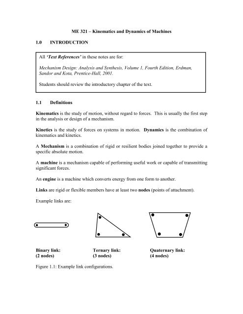
1.0 INTRODUCTION<strong>ME</strong> <strong>321</strong> – <strong>Kinematics</strong> <strong>and</strong> <strong>Dynamics</strong> <strong>of</strong> <strong>Machines</strong>All ‘Text References’ in these notes are for:Mechanism Design: Analysis <strong>and</strong> Synthesis, Volume 1, Fourth Edition, Erdman,S<strong>and</strong>or <strong>and</strong> Kota, Prentice-Hall, 2001.Students should review the introductory chapter <strong>of</strong> the text.1.1 Definitions<strong>Kinematics</strong> is the study <strong>of</strong> motion, without regard to forces. This is usually the first stepin the analysis or design <strong>of</strong> a mechanism.Kinetics is the study <strong>of</strong> forces on systems in motion. <strong>Dynamics</strong> is the combination <strong>of</strong>kinematics <strong>and</strong> kinetics.A Mechanism is a combination <strong>of</strong> rigid or resilient bodies joined together to provide aspecific absolute motion.A machine is a mechanism capable <strong>of</strong> performing useful work or capable <strong>of</strong> transmittingsignificant forces.An engine is a machine which converts energy from one form to another.Links are rigid or flexible members have at least two nodes (points <strong>of</strong> attachment).Example links are:Binary link: Ternary link: Quaternary link:(2 nodes) (3 nodes) (4 nodes)Figure 1.1: Example link configurations.
<strong>ME</strong> <strong>321</strong> – <strong>Kinematics</strong> <strong>and</strong> <strong>Dynamics</strong> <strong>of</strong> <strong>Machines</strong> S. Lambert Winter 2002Curvilinear translation: points in the body move along identical curves, <strong>and</strong> so thelink does not rotate with respect to the ground (ex., link connecting two disks inFigure 1.3).Rotation: points in the body rotate about a single point, which is usually fixed to theground (ex., disks in Figure 1.3).General planar motion: a general combination <strong>of</strong> rotation <strong>and</strong> translation (ex.,connecting rod joining piston <strong>and</strong> disk in Figure 1.3).Figure 1.3: Example mechanism showing different types <strong>of</strong> planar motion.We classify linkages in terms <strong>of</strong> the number <strong>of</strong> links. A dyad, Figure 1.4, is two linkswith one joint, usually a pin joint. By itself, it does not usually constitute a usefullinkage, but the term is sometimes used to indicate parts <strong>of</strong> a more complex linkage. Inaddition, a dyad may be added to an existing linkage to transmit motion from a motor(rotation) to the linkage.Figure 1.4: Example dyad.Similarly, three links (a triad), Figure 1.6, can not usually be used alone to form a usefulmechanism. It either represents a part <strong>of</strong> a more complex mechanism, or a structure.Figure 1.5: Example traids.The most useful mechanism has four links – the four-bar mechanism. There are twobasic configurations. In one case, the four links are joined by 4 pin-joints. In the other3
<strong>ME</strong> <strong>321</strong> – <strong>Kinematics</strong> <strong>and</strong> <strong>Dynamics</strong> <strong>of</strong> <strong>Machines</strong> S. Lambert Winter 2002case, a slider joint replaces one <strong>of</strong> the pin joints. Schematic <strong>and</strong> simplified (skeleton)diagrams <strong>of</strong> each are shown in Figure 1.6.An mechanism inversion is said to occur when the fixed link is allowed to move, <strong>and</strong> analternative link is fixed. The relative motion between the links remains unchanged, butthe absolute motion, <strong>and</strong> the function <strong>of</strong> the mechanism is changed. This is mostdramatically seen in the various inversions <strong>of</strong> the slider-crank mechanism, Figure 1.7.Figure 1.6: Example four-bar linkage <strong>and</strong> slider crank.4
<strong>ME</strong> <strong>321</strong> – <strong>Kinematics</strong> <strong>and</strong> <strong>Dynamics</strong> <strong>of</strong> <strong>Machines</strong> S. Lambert Winter 2002Figure 1.7: Various inversions <strong>of</strong> the slider-crack mechanism, from top to bottom:conventional engine, rotary engine, quick-return mechanism, <strong>and</strong> pump.1.2 Degrees <strong>of</strong> FreedomText Reference: Degrees <strong>of</strong> freedom <strong>and</strong> Gruebler’s equation are covered in section1.7 <strong>of</strong> the text, pages 21-30.5
<strong>ME</strong> <strong>321</strong> – <strong>Kinematics</strong> <strong>and</strong> <strong>Dynamics</strong> <strong>of</strong> <strong>Machines</strong> S. Lambert Winter 2002By working with Gruebler’s equation, we can examine the possible combinations <strong>of</strong> links<strong>and</strong> joints which we can use to form a mechanism with a specified number <strong>of</strong> degrees <strong>of</strong>freedom. Generally, we are after 1 d<strong>of</strong>.Consider a mechanism with 2 links. Since 1 link is assumed fixed, we start out with 3d<strong>of</strong>, <strong>and</strong> reduce this to 1 by adding a single pin or slider joint, Figure 1.8. This is not aparticularly useful mechanism, since we get out pretty much what we put in: a rotation inthe first case <strong>and</strong> a translation in the second case. Note that we could also use two rollsliderjoints to constrain the second link, as shown at right in Figure 1.8. This is notparticularly useful either.2211Figure 1.8: Example 2-bar mechanismsNow consider a mechanism with 3 links. In this case, we start out with 6 d<strong>of</strong>, <strong>and</strong> mustadd joints to constrain 5 d<strong>of</strong> to be left with 1 d<strong>of</strong>. This is possible with two pins <strong>and</strong> aroll-slider joint, since the latter only constrains 1 d<strong>of</strong>. This is an example <strong>of</strong> a camfollowermechanism. Replacing one <strong>of</strong> the pins with a slider results in the moreconventional cam-follower mechanism shown at right in Figure 1.9.313221 11Figure 1.9: Example 3-bar mechanisms.With four bars, <strong>and</strong> four pins, we get the st<strong>and</strong>ard 4-bar mechanism, Figure 1.10.Replacing one pin with a slider gives the slider-crank mechanism, Figure 1.10, <strong>and</strong> itsvarious inversions, Figure 1.7.8
<strong>ME</strong> <strong>321</strong> – <strong>Kinematics</strong> <strong>and</strong> <strong>Dynamics</strong> <strong>of</strong> <strong>Machines</strong> S. Lambert Winter 200223546234561 1Watt I1 1 1Watt IIFigure 1.12: Watt six-bar mechanisms (note that the ground is a ternary member for theWatt II mechanism.56623423 451 1Stephenson I1 1Stephenson II352461 2 3Stephenson IIIFigure 1.13: Stephenson six-bar mechanisms.10