The Testing of Vacuum Generator Circuit Breakers
The Testing of Vacuum Generator Circuit Breakers
The Testing of Vacuum Generator Circuit Breakers
You also want an ePaper? Increase the reach of your titles
YUMPU automatically turns print PDFs into web optimized ePapers that Google loves.
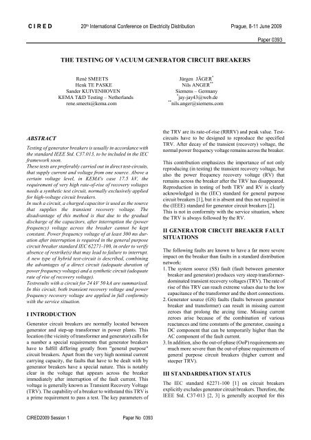
C I R E D 20 th International Conference on Electricity Distribution Prague, 8-11 June 2009Paper 0393THE TESTING OF VACUUM GENERATOR CIRCUIT BREAKERSRené SMEETS Jürgen JÄGER *Henk TE PASKE Nils ANGER **Sander KUIVENHOVENSiemens – GermanyKEMA T&D <strong>Testing</strong> – Netherlands* jay-jay43@web.derene.smeets@kema.com** nils.anger@siemens.comABSTRACT<strong>Testing</strong> <strong>of</strong> generator breakers is usually in accordance withthe standard IEEE Std. C37.013, to be included in the IECframework soon.<strong>The</strong>se tests are preferably carried out in direct test-circuits,that supply current and voltage from one source. Above acertain voltage level, in KEMA's case 17.5 kV, therequirement <strong>of</strong> very high rate-<strong>of</strong>-rise <strong>of</strong> recovery voltagesneeds a synthetic test circuit, normally exclusively appliedfor high-voltage circuit breakers.In such a circuit, a charged capacitor is used as the sourcethat supplies the transient recovery voltage. <strong>The</strong>disadvantage <strong>of</strong> this method is that due to the gradualdischarge <strong>of</strong> the capacitors, after interruption the (powerfrequency) voltage across the breaker cannot be keptconstant. Power frequency voltage <strong>of</strong> at least 300 ms durationafter interruption is required in the general purposecircuit breaker standard IEC 62271-100, in order to verifyabsence <strong>of</strong> restrike(s) that may lead to failure to interrupt.A new type <strong>of</strong> hybrid test-circuit is described, combiningthe advantages <strong>of</strong> a direct circuit (adequate duration <strong>of</strong>power frequency voltage) and a synthetic circuit (adequaterate <strong>of</strong> rise <strong>of</strong> recovery voltage).Testresults with a circuit for 24 kV 50 kA are summarized.In this circuit, both transient recovery voltage and powerfrequency recovery voltage are applied in full conformitywith the service situation.I INTRODUCTION<strong>Generator</strong> circuit breakers are normally located betweengenerator and step-up transformer in power plants. Thislocation (the vicinity <strong>of</strong> transformer and generator) calls fora number a special requirements that generator breakershave to fulfill differing greatly from "general purpose"circuit breakers. Apart from the very high nominal currentcarrying capacity, the faults that have to be dealt with bygenerator breakers have a special nature. This is notablyclear in the voltage that appears across the breakerimmediately after interruption <strong>of</strong> the fault current. Thisvoltage is generally known as Transient Recovery Voltage(TRV). <strong>The</strong> capability <strong>of</strong> a breaker to withstand this TRV isa prime requirement to pass a test. <strong>The</strong> key parameters <strong>of</strong>the TRV are its rate-<strong>of</strong>-rise (RRRV) and peak value. Testcircuitshave to be designed to reproduce the specifiedTRV. After decay <strong>of</strong> the transient (recovery) voltage, thenormal power frequency voltage remains across the breaker.This contribution emphasizes the importance <strong>of</strong> not onlyreproducing (in testing) the transient recovery voltage, butalso the power frequency recovery voltage (RV) thatremains across the breaker after the TRV has disappeared.Reproduction in testing <strong>of</strong> both TRV and RV is clearlyacknowledged in the (IEC) standard for general purposecircuit breakers [1], but it is absent and thus not required inthe (IEEE) standard for generator circuit breakers [2].This is not in conformity with the service situation, wherethe TRV is always followed by the RV.II GENERATOR CIRCUIT BREAKER FAULTSITUATIONS<strong>The</strong> following faults are known to have a far more severeimpact on the breaker than faults in a standard distributionnetwork:1. <strong>The</strong> system source (SS) fault (fault between generatorbreaker and generator) produces very steep transformerdominatedtransient recovery voltages (TRV). <strong>The</strong> rate <strong>of</strong>rise <strong>of</strong> this TRV can reach extreme values due to the lowcapacitance <strong>of</strong> the transformer and the short connections.2. <strong>Generator</strong> source (GS) faults (faults between generatorbreaker and transformer) can result in missing currentzeroes that prolong the arcing time. Missing currentzeroes arise because <strong>of</strong> the combination <strong>of</strong> variousreactances and time constants <strong>of</strong> the generator, causing aDC component that can be temporarily higher than theAC component <strong>of</strong> the fault current.3. In addition, also the out-<strong>of</strong>-phase (OoP) requirements aremuch more severe than the out-<strong>of</strong>-phase requirements <strong>of</strong>general purpose circuit breakers (higher current andsteeper TRV).III STANDARDISATION STATUS<strong>The</strong> IEC standard 62271-100 [1] on circuit breakersexplicitly excludes generator circuit breakers. <strong>The</strong>refore, theIEEE Std. C37-013 [2, 3] is generally accepted for thisCIRED2009 Session 1 Paper No 0393
C I R E D 20 th International Conference on Electricity Distribution Prague, 8-11 June 2009Paper 0393TRV (kV)6050403020100OOP faultSS faultGS faultenvelope for generalpurpose CB T100envelope for generalpurpose CB OOP0 20 40 60 80 100 120time (us)Fig. 1: Standardized values <strong>of</strong> TRV <strong>of</strong> generator (for 200-400 MVA transformers, red ) - and general purpose circuitbreaker (blue). Rated voltage is 24 kV.purpose, and will be included in the IEC framework in 2009by a joint IEEE / IEC working group.III 1 Transient recovery voltageIn fig. 1, (IEEE) standardized values <strong>of</strong> TRV's <strong>of</strong> 24 kVgenerator breakers for step-up transformer rated 200-400MVA are compared with (IEC [1]) standardized 24 kVbreakers for distribution systems. In the generator breakercase, IEEE prescribes the (sinusoidal) TRV waveshapesdirectly: in fig. 1 the TRVs associated with system source(SS), generator source (GS) and out-<strong>of</strong>-phase (OOP) fault.In the general purpose breaker case, IEC prescribes only therequired TRV envelopes: in fig. 1 the terminal fault (100%rated short-circuit breaking current) and out-<strong>of</strong>-phase faults(25% rated short-circuit breaking current).From the figure it is immediately clear that the rate-<strong>of</strong>-risedepends greatly on the application: either generator- ordistribution application.III 2 Power frequency recovery voltage<strong>The</strong> pole <strong>of</strong> the breaker most severely stressed is the firstpole-to-clear.<strong>The</strong> power frequency recovery voltage acrossthis pole has temporarily a value <strong>of</strong> 1.5 times the phase-togroundvoltage (in medium voltage networks). <strong>The</strong> elevatedvoltage lasts until all phases have interrupted (after a quartercycle) the current. After this temporarily elevated powerfrequency voltage, the rated power frequency voltage (atphase-to-ground value) sets in and remains.In fig. 2a, all components <strong>of</strong> voltage across a breaker (inthis case a 24 kV generator breaker) are outlined.III 2.1 Direct testsFor general purpose circuit breakers, IEC 62271-100 clause6.104.7 [1] requires the presence <strong>of</strong> at least 95% <strong>of</strong> the(phase-to-ground) power frequency voltage until 300 msafter interruption. This is to verify the dielectrical withstand<strong>of</strong> the breaker also beyond the TRV region, where theswitchgear has not yet reached a mechanically (and possibledielectrically) stable situation.In direct test circuits, where current and voltage are suppliedfrom the same source, this is a natural situation. In thissense, direct testing (especially three-phase) is the bestsimulation <strong>of</strong> network reality. Distribution breakers arenormally tested by this method and in three-phase testcircuits voltage stresses are like in fig. 2a.50403020100-10-2050403020100-10-2050403020100-10-20transient recovery voltagetemporary pow freq voltage for first-pole-to-clearpermanent power frequency recovery voltage0 50 100 150 200 250 300transient recovery voltagereality & direct three-phase testingDC revovery voltagesynthetic testing with unipolar recovery0 50 100 150 200 250 300transient recovery voltageoscillatory recovery voltagesynthetic testing with oscillatory recovery0 50 100 150 200 250 300Fig. 2: Recovery voltage across breaker:a: upper: in network and in three-phase direct testingb: middle: in synthetic testing with unipolar recovery voltagec: lower: in synthetic testing with damped oscillatory recoveryIII 2.2 Synthetic testsIn synthetic test circuits, normally applied for high-voltagecircuit breaker testing, current is normally supplied by agenerator (or power grid, or capacitor bank) and recoveryvoltage is supplied by a pre-charged capacitor bank.Whereas such a capacitor bank is very well suited to supplythe adequate TRV, it cannot maintain an adequate recoveryvoltage for a sufficiently long time.Basically, there are two possibilities:1) Maintain the remaining capacitor bank voltage as aunipolar (DC) voltage across the breaker. This isunrealistic, and stresses the test-object in a way veryCIRED2009 Session X Paper No 0393 Page 2 / 4


