SELECT DIRECT-VENT Residential Gas Water Heaters
SELECT DIRECT-VENT Residential Gas Water Heaters
SELECT DIRECT-VENT Residential Gas Water Heaters

Create successful ePaper yourself
Turn your PDF publications into a flip-book with our unique Google optimized e-Paper software.
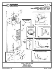
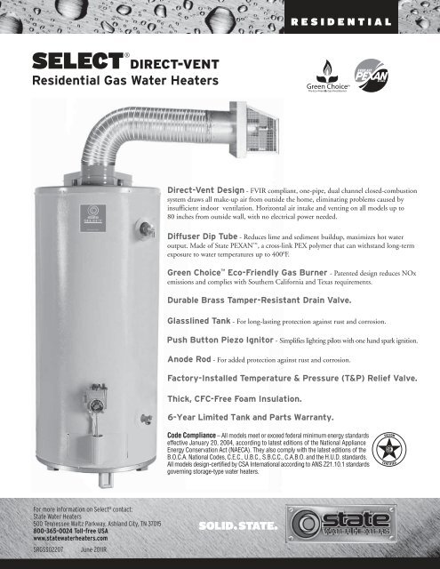
RESIDENTIAL<strong>SELECT</strong> <strong>DIRECT</strong>-<strong>VENT</strong><strong>Residential</strong> <strong>Gas</strong> <strong>Water</strong> <strong>Heaters</strong>Direct-Vent Design - FVIR compliant, one-pipe, dual channel closed-combustionsystem draws all make-up air from outside the home, eliminating problems caused byinsufficient indoor ventilation. Horizontal air intake and venting on all models up to80 inches from outside wall, with no electrical power needed.Diffuser Dip Tube - Reduces lime and sediment buildup, maximizes hot wateroutput. Made of State PEXAN , a cross-link PEX polymer that can withstand long-termexposure to water temperatures up to 400 0 F.Green Choice Eco-Friendly <strong>Gas</strong> Burner - Patented design reduces NOxemissions and complies with Southern California and Texas requirements.Durable Brass Tamper-Resistant Drain Valve.Glasslined Tank - For long-lasting protection against rust and corrosion.Push Button Piezo Ignitor - Simplifies lighting pilots with one hand spark ignition.Anode Rod - For added protection against rust and corrosion.Factory-Installed Temperature & Pressure (T&P) Relief Valve.Thick, CFC-Free Foam Insulation.6-Year Limited Tank and Parts Warranty.For more information on Select ® contact:State <strong>Water</strong> <strong>Heaters</strong>500 Tennessee Waltz Parkway, Ashland City, TN 37015800-365-0024 Toll-free USAwww.statewaterheaters.comSRGSS02207 June 2011R
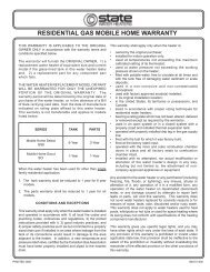
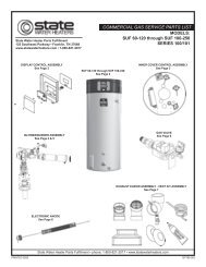
RESIDENTIAL<strong>SELECT</strong> <strong>DIRECT</strong>-<strong>VENT</strong><strong>Residential</strong> <strong>Gas</strong> <strong>Water</strong> <strong>Heaters</strong>MODELNUMBERFIRSTHOURRATINGENERGYFACTORGALLONCAPBTUINPUTRECOVERYDIMENSIONS90 DEGREERISE A *** B C D E F<strong>VENT</strong>PIPE **SHIPPINGWEIGHTGS6 40 YBDS730.624038,000416854-3/422-1/41612-1/445-1/4Co-Axial167GS6 50 YBDS870.605042,000457663-3/422-1/41612-1/454Co-Axial185GS6 50 YRDS880.595050,000557664-3/422-1/416-1/412-1/255-1/2Co-Axial187GS6 75 YRDS 131 0.59 75 55,000 60 76 65-3/4 26-1/4 16-1/4 12-1/2 55-1/2 Co-Axial 310Recoveries are rounded to nearest gallon<strong>Water</strong> Connections - 3/4” on all models**Dual-channel system has 3” vent pipe inside 6” air intake pipe for the 40 & 50-gallon. The 75-gallon models uses a 4” x 7” Co-Axial pipe.***A dimension is to center line of flue (recommended vent height)When ordering Propane, change “Y” to “H” in model number (GS6 40 HBDS)All models have 2” foam cavity75-gallon water connections are 12” on center.25-1/4 for40 & 50-gallon29-1/2 for75-gallonImportant! Vent Installation and Termination RequirementsT & P• Maximum horizontal vent distance is 80” to outside of exterior wall.• Minimum horizontal vent distance is 17” to outside of exterior wall.• Vent pipes may be trimmed (cut) for short vent installations.• For vent installation less than 30” the vent restrictor is required. Placerestrictor over the flue outlet on heater before installing the outlet ventpipe to the heater.• Recommended installation height for the heater and vent pipe should be68” for 40-gallon models and 76” for the 50 and 75-gallon models (ventheight).• Offset Vent Arrangement1. When replacing an existing direct vent model, the new vent pipe may dropfrom the minimum vent height as much as 7 1/4” to exit through theexisting vent opening in the exterior wall.2. Vent may have one horizontal 90 degree turn before exiting throughexterior wall (Do not combine both offset vent arrangements in oneinstallation) (See examples in the installation manual)• High Rise Vent Arrangement3. When vent termination is more than 80” above the base of the heater.The horizontal vent run must be a minimum of 22” from the center of theheater to the outside exterior wall surface. (See example in theinstallation manual)• Vent termination clearance hole through the exterior wall should beapproximately 7” diameter.• Snow accumulation and drifting should be considered when locating thetermination.• An optional wire grill vent cap protector is available through the partsdepartment. Request part number 9006627.• See the installation manual for complete installation and ventingrequirements.ABCMIN <strong>VENT</strong>17MAX <strong>VENT</strong>806“ DIA. ON 40 & 50-GALLON MODELS7” DIA. ON 75-GALLON MODELSFTOP42°47°EXTERIORWALLD R A I N75-GALLON <strong>VENT</strong>TERMINATION CAPIS NOTINTERCHANGEABLEWITH THE <strong>VENT</strong>CAP ON THE40 & 50-GALLONMODELS.DEFor complete information on limited warranties,consult written warranty, or contact the StateCustomer Care Center, 1-800-365-0024.FRONTFor more information on Select ® contact:State <strong>Water</strong> <strong>Heaters</strong>500 Tennessee Waltz Parkway, Ashland City, TN 37015800-365-0024 Toll-free USAwww.statewaterheaters.comSRGSS02207June 2011R