
Create successful ePaper yourself
Turn your PDF publications into a flip-book with our unique Google optimized e-Paper software.
Product Overview.............................................................. 4Package Contents......................................................................... 4System Requirements.................................................................. 4Hardware Overview........................................................... 5Front........................................................................................... 5Rear............................................................................................ 6Side............................................................................................. 7Configuration..................................................................... 8Configuration with Wizard......................................................... 8Web-based Configuration Utility..........................................13D-ViewCam Setup Wizard................................................15Live Video.......................................................................................17Setup...............................................................................................19Wizard......................................................................................19Internet Connection Setup Wizard...............................19Motion Detection Setup Wizard....................................22Network Setup.....................................................................24Wireless Setup(DCS-2230 only)......................................26Dynamic DNS........................................................................27Image Setup..........................................................................28Audio and Video..................................................................30Preset.......................................................................................32Motion Detection................................................................34Time and Date......................................................................35Event Setup...........................................................................36Application........................................................................37Add Server.........................................................................38Table of ContentsAdd Media..........................................................................39Add Event...........................................................................41Add Recording..................................................................43SD Card...................................................................................45Advanced.......................................................................................46Digital Input/Output..........................................................46ICR and IR...............................................................................47HTTPS......................................................................................48Access List..............................................................................49Maintenance.................................................................................50Device Management..........................................................50Backup and Restore............................................................51Firmware Upgrade..............................................................52Status...............................................................................................53Device Info.............................................................................53Logs..........................................................................................54Help..........................................................................................55Appendix..........................................................................56DI/DO Input Specifications......................................................56Technical Specifications............................................................57Technical Specifications............................................................58Contacting Technical Support.........................................60Warranty...........................................................................61Registration......................................................................67D-<strong>Link</strong> DCS-2210/2230 User Manual2
PrefaceD-<strong>Link</strong> reserves the right to revise this publication and to make changes in the contents hereof without obligation to notify any person ororganization of such revisions or changes.Manual RevisionsRevision Date Description1.0 October 13, 2011 DCS-2210/2230 Revision A1 with firmware version 1.00TrademarksD-<strong>Link</strong> and the D-<strong>Link</strong> logo are trademarks or registered trademarks of D-<strong>Link</strong> Corporation or its subsidiaries in the United States or othercountries. All other company or product names mentioned herein are trademarks or registered trademarks of their respective companies.Copyright © 2011 D-<strong>Link</strong> Corporation.All rights reserved. This publication may not be reproduced, in whole or in part, without prior expressed written permission from D-<strong>Link</strong> Systems, Inc.D-<strong>Link</strong> DCS-2210/2230 User Manual3
Product OverviewPackage ContentsDCS-2210 or DCS-2230 Full HD PoE/Wireless N Cube Network CameraCamera standCAT5 Ethernet cablePower adapterCD-ROM with User Manual and softwareQuick Installation GuideIf any of the above items are missing, please contact your reseller.System Requirements• Existing 10/100 Ethernet-based network or 802.11n/g wireless network(Wireless for DCS-2230 )• Computer with Windows 7/Vista/XP for Camera Setup Wizard• Internet Explorer, Firefox, Opera, or other web browser for web interface (Internet Explorerrecommended for full functionality)If any of the above items are missing, please contact your reseller.D-<strong>Link</strong> DCS-2210/2230 User Manual4
Hardware OverviewHardware OverviewFront512368741 Status LED Indicates the camera's current status2 ICR SensorThe IR-Cut Removable sensor monitors lighting conditions and switches betweencolor and infrared accordingly3 Infrared LED Used to illuminate the camera's field of view at night4 PIR Passive Infrared sensor for motion detect5 Camera Lens Records video of the surrounding area6 Microphone Records audio from the surrounding area7 WPS LED (DCS2230 only) WPS status indicator LED8 Speaker Audio outputD-<strong>Link</strong> DCS-2210/2230 User Manual5
Hardware OverviewRear15432671 Ethernet2 WPS Button (DCS-2230 only)RJ45 connector for Ethernet (DCS-2210 support PoE which can also be used topower the camera)Press this button, then press the WPS button on your router to set up a wirelessconnection automatically3 Reset Press and hold this button for 10 seconds to reset the camera4 Power Connector Connects to the included DC 5 V power adapter5 I/O Connector I/O connectors for external devices6 Adjustment Ring Tighten or loosen the adjustment ring to adjust the camera's position7 WPS LED (DCS2230 only) Can be used with cable ties to attach camera to a surfaceD-<strong>Link</strong> DCS-2210/2230 User Manual6
Hardware OverviewSide11 Micro SD Card Slot Local storage for storing recorded image and videoD-<strong>Link</strong> DCS-2210/2230 User Manual7
ConfigurationConfiguration with WizardInsert the DCS-2210/DCS-2230 CD into your computer's CD-ROM drive to begin the installation. If the Autorun function on your computer isdisabled, or if the D-<strong>Link</strong> Launcher fails to start automatically, click Start > Run. Type D:\autorun.exe, where D: represents the drive letter of yourCD-ROM drive.Click Installation Wizard to begin the installation.After clicking Setup Wizard, the window on the right will open.Click Next to continue.D-<strong>Link</strong> DCS-2210/2230 User Manual8
ConfigurationClick Yes to accept the License Agreement.To start the installation process, click Next.Note: The installation may take several minutes to finish.D-<strong>Link</strong> DCS-2210/2230 User Manual9
ConfigurationClick Finish to complete the installation.Click on the D-<strong>Link</strong> Setup Wizard SE icon that was created in your Windows Startmenu.Start > D-<strong>Link</strong> > Setup Wizard SED-<strong>Link</strong> DCS-2210/2230 User Manual10
ConfigurationThe Setup Wizard will appear and display the MAC address and IP address of yourcamera(s). If you have a DHCP server on your network, a valid IP Address will be displayed.If your network does not use a DHCP server, the network camera's default static IP address192.168.0.20 will be displayed.Click the Wizard button to continue.Enter the Admin ID and password. When logging in for the first time, the default AdminID is admin with the password left blank.Click Next, to proceed to the next page.D-<strong>Link</strong> DCS-2210/2230 User Manual11
ConfigurationSelect DHCP if your camera obtains an IP address automatically when it boots up. Selectstatic IP if the camera will use the same IP address each time it is started.Click Next, to proceed to the next page.Take a moment to confirm your settings and click Restart.D-<strong>Link</strong> DCS-2210/2230 User Manual12
ConfigurationWeb-based Configuration UtilityThis section explains how to configure your new D-<strong>Link</strong> Network Camera using the Web-based Configuration Utility.Click on the D-<strong>Link</strong> Setup Wizard SE icon that was created in your Windows Start menu.Start > D-<strong>Link</strong> > Setup Wizard SESelect the camera and click the button labeled "<strong>Link</strong>" to access the web configuration.The Setup Wizard will automatically open your web browser to the IP address of thecamera.Alternatively, you may manually open a browser and enter the IP address of thecamera: 192.168.0.20D-<strong>Link</strong> DCS-2210/2230 User Manual13
ConfigurationEnter admin as the default username and leave the password blank.Click OK to continue.This section shows your camera’s live video. You can select your video profile and view oroperate the camera. For additional information about web configuration, please refer tothe user manual included on the CD-ROM or the D-<strong>Link</strong> website.D-<strong>Link</strong> DCS-2210/2230 User Manual14
ConfigurationD-ViewCam Setup WizardD-ViewCam software is included for the administrator to manage multiple D-<strong>Link</strong> IPcameras remotely. You may use the software to configure all the advanced settings foryour cameras. D-ViewCam is a comprehensive management tool for IP surveillance.Insert the CD-ROM into the CD-ROM drive. Click "Install D-ViewCam Software" fromthe menu, and select "D-ViewCam" to install the VMS software.Follow the Installation Wizard to install D-ViewCam.Click Next to continue.D-<strong>Link</strong> DCS-2210/2230 User Manual15
ConfigurationClick Finish to complete the installation.To start the D-ViewCam, select Start > All Programs > D-<strong>Link</strong> D-ViewCam >Main Console.For more detail operation of using D-ViewCam software, please refer to D-ViewCamManual.D-<strong>Link</strong> DCS-2210/2230 User Manual16
ConfigurationGo To:(Preset List)SD Status:IO Status:PTZ Control:ePTZ Speed:Global View:Language:If any presets have been defined, selecting a preset from this list willdisplay it.This option displays the status of the SD card. If no SD card has beeninserted, this screen will display the message "Card Invalid."This option displays the status of your I/O device if a device has beenconnected.This camera uses electronic pan/tilt/zoom (ePTZ) to select and viewareas of interest in the field of view. Please see page 30 for informationabout setting the frame size and view window area.You may select a value between 0 and 64. 0 is the slowest and 64 isthe fastest.This window indicates the total field of view (FOV) of the camera. Thered box indicates the visible region of interest (ROI).You may select the interface language using this menu.Auto PanStopPreset PathStarts the automaticpanning function. TheROI will pan from backand forth within theFOVStops the camera ePTZmotionStarts the camera'smotion along thepredefined pathD-<strong>Link</strong> DCS-2210/2230 User Manual18
ConfigurationSetupWizardTo configure your Network Camera, click Internet Connection SetupWizard. Alternatively, you may click Manual Internet Connection Setupto manually configure your Network Camera and skip to page 26.To quickly configure your Network Camera’s motion detection settings,click Motion Detection Setup Wizard. If you want to enter your settingswithout running the wizard, click Manual Motion Detection Setup andskip to page 34.Internet Connection Setup WizardThis wizard will guide you through a step-by-step process to configureyour new D-<strong>Link</strong> Camera and connect the camera to the internet. ClickNext to continue.Note: Select DHCP if you are unsure of which settings to choose.Click Next to continue.D-<strong>Link</strong> DCS-2210/2230 User Manual19
ConfigurationSelect Static IP if your Internet Service Provider has provided you with connectionsettings, or if you wish to set a static address within your home network. Enterthe correct configuration information and click Next to continue.If you are using PPPoE, select Enable PPPoE and enter your user name andpassword, otherwise click Next to continue.If you have a Dynamic DNS account and would like the camera to update yourIP address automatically, Select Enable DDNS and enter your host information.Click Next to continue.Enter a name for your camera and click Next to continue.D-<strong>Link</strong> DCS-2210/2230 User Manual20
ConfigurationConfigure the correct time to ensure that all events will be triggered asscheduled. Click Next to continue.If you have selected DHCP, you will see a summary of your settings,including the camera's IP address. Please write down all of thisinformation as you will need it in order to access your camera.Click Apply to save your settings.D-<strong>Link</strong> DCS-2210/2230 User Manual21
ConfigurationThis wizard will guide you through a step-by-step process to configure your camera'smotion detection functions.Click Next to continue.Motion Detection Setup WizardStep 1This step will allow you to enable or disable motion detection, specify the detectionsensitivity, and adjust the camera’s ability to detect movement.You may specify whether the camera should capture a snapshot or a video clip whenmotion is detected.Please see the Motion Detection section on page 34 for information about how toconfigure motion detection.Step 2This step allows you to enable motion detection based on a customized schedule.Specify the day and hours. You may also choose to always record motion.D-<strong>Link</strong> DCS-2210/2230 User Manual22
ConfigurationStep 3This step allows you to specify how you will receive event notifications fromyour camera. You may choose not to receive notifications, or to receivenotifications via e-mail or FTP.Please enter the relevant information for your e-mail or FTP account.Click Next to continue.Step 4You have completed the Motion Detection Wizard.Please verify your settings and click Apply to save them.Please wait a few moments while the camera saves your settings and restarts.D-<strong>Link</strong> DCS-2210/2230 User Manual23
ConfigurationNetwork SetupUse this section to configure the network connections for your camera. All relevant information must be entered accurately. After making anychanges, click the Save Settings button to save your changes.LAN Settings:DHCP:Static IP Address:This section lets you configure settings for your localarea network.Select this connection if you have a DHCP serverrunning on your network and would like your camerato obtain an IP address automatically.You may obtain a static or fixed IP address and othernetwork information from your network administratorfor your camera. A static IP address may simplify accessto your camera in the future.IP Address:Enter the fixed IP address in this field.Subnet Mask:Default Gateway:Primary DNS:Secondary DNS:Enable UPnP:This number is used to determine if the destination is inthe same subnet. The default value is 255.255.255.0.The gateway used to forward frames to destinations ina different subnet. Invalid gateway settings may causethe failure of transmissions to a different subnet.The primary domain name server translates names to IPaddresses.The secondary DNS acts as a backup to the primaryDNS.Enabling this setting allows your camera to be configuredas a UPnP device on your network.D-<strong>Link</strong> DCS-2210/2230 User Manual24
ConfigurationEnable UPnP Port Forwarding:Enabling this setting allows the camera to add portforwarding entries into the router automatically on aUPnP capable network.Enable PPPoE:Enable this setting if your network uses PPPoE.User Name / Password:Enter the username and password for your PPPoEaccount. Re-enter your password in the ConfirmPassword field. You may obtain this information fromyour ISP.HTTP Port:The default port number is 80.Access Name for Stream 1~3:HTTPS Port:RTSP Port:Maximum Upload/<strong>Download</strong>Bandwidth:The default name is video#.mjpg, where # is the numberof the stream.You may use a PC with a secure browser to connect tothe HTTPS port of the camera. The default port numberis 443.The port number that you use for RTSP streaming tomobile devices, such as mobile phones or PDAs. Thedefault port number is 554. You may specify the addressof a particular stream. For instance, live1.sdp can beaccessed at rtsp://x.x.x.x/video1.sdp where the x.x.x.xrepresents the ip address of your camera.Specifying the maximum download/upload bandwidthfor each socket can be useful when connecting yourdevice to a busy or heavily loaded network. Enteringa value of '0' indicates that the camera should notmonitor bandwidth. Specifying other values will limitthe camera's transfer speed to the specified number ofkilobytes per second.D-<strong>Link</strong> DCS-2210/2230 User Manual25
ConfigurationWireless Setup(DCS-2230 only)This section allows you to set up and configure the wireless settings on your camera. After making any changes, click the Save Settings button tosave your changes.Site Survey:SSID:Wireless Mode:Channel:Authentication:Encryption:Key:Click the Rescan button to scan for available wirelessnetworks. After scanning, you can use the drop-downbox to select an available wireless network. Therelated information (SSID, Wireless Mode, Channel,Authentication, Encryption) will be automatically filledin for you.Enter the SSID of the wireless access point you wish touse.Use the drop-down box to select the mode of thewireless network you wish to connect to. Infrastructureis normally used to connect to an access point or router.Ad-Hoc is usually used to connect directly to anothercomputer.If you are using Ad Hoc mode, select the channel of thewireless network you wish to connect to, or select Auto.Select the authentication you use on your wirelessnetwork - Open, Shared, WPA-PSK, or WPA2-PSK.If you use WPA-PSK or WPA2-PSK authentication, youwill need to specify whether your wireless networkuses TKIP or AES encryption. If you use Open or Sharedauthentication, WEP encryption should be the setting.If you use WEP, WPA-PSK, or WPA2-PSK authentication,enter the Key (also known as password) used for yourwireless network.D-<strong>Link</strong> DCS-2210/2230 User Manual26
ConfigurationDynamic DNSDDNS (Dynamic Domain Name Server) will hold a DNS host name and synchronize the public IP address of the modem when it has been modified.A user name and password are required when using the DDNS service. After making any changes, click the Save Settings button to save yourchanges.Enable DDNS:Select this checkbox to enable the DDNS function.Server Address:Select your Dynamic DNS provider from the pull downmenu or enter the server address manually.Host Name:Enter the host name of the DDNS server.User Name:Password:Enter the user name or e-mail used to connect to yourDDNS account.Enter the password used to connect to your DDNSserver account.Timeout:Enter the DNS Timeout values you wish to use.Status:Indicates the connection status, which is automaticallydetermined by the system.D-<strong>Link</strong> DCS-2210/2230 User Manual27
ConfigurationImage SetupIn this section, you may configure the video image settings for your camera. A preview of the image will be shown in Live Video.Enable PrivacyMask:The Privacy Mask setting allows you to specify up to 3 rectangular areason the camera's image to be blocked/excluded from recordings andsnapshots.You may click and drag the mouse cursor over the camera image to drawa mask area.Right clicking on the camera image brings up the followingmenu options:Disable All: Disables all mask areasEnable All: Enables all mask areasReset All: Clears all mask areas.Anti Flicker:Mirror:Flip:Power Line:White Balance:Exposure Mode:Denoise:Brightness:If the video flickers, try enabling this setting.This will mirror the image horizontally.This will flip the image vertically. When turning Flip on, you may want toconsider turning Mirror on as well.Select the frequency used by your power lines to avoid interference ordistortion.Use the drop-down box to change white balance settings to help balance colors for different environments. You can choosefrom Auto, Outdoor, Indoor, Fluorescent, and Push Hold.Changes the exposure mode. Use the drop-down box to set the camera for Indoor, Outdoor, or Night environments, or toMoving to capture moving objects. The Low Noise option will focus on creating a high-quality picture without noise. You canalso create 3 different custom exposure modes. The Max Gain setting will allow you to control the maximum amount of gain toapply to brighten the picture.This setting controls the amount of noise reduction that will be applied to the picture.Adjust this setting to compensate for backlit subjects.D-<strong>Link</strong> DCS-2210/2230 User Manual28
ConfigurationContrast:Saturation:Sharpness:Reset Default:Adjust this setting to alter the color intensity/strength.This setting controls the amount of coloration, from grayscale to fully saturated.Specify a value from 0 to 8 to specify how much sharpening to apply to the image.Click this button to reset the image to factory default settings.D-<strong>Link</strong> DCS-2210/2230 User Manual29
ConfigurationAudio and VideoYou may configure up to 3 video profiles with different settings for your camera. Hence, you may set up different profiles for your computerand mobile display. In addition, you may also configure the two-way audio settings for your camera. After making any changes, click the SaveSettings button to save your changes.Number of active profiles:Aspect ratio:Mode:Frame size / View window area:Maximum frame rate:You can use the drop-down box to set up to 3 activeprofiles.Set the aspect ratio of the video to 4:3 standard or16:9 widescreen.Set the video codec to be used to JPEG, MPEG-4, orH.264.Frame size determines the total capture resolution,and View window area determines the Live Videoviewing window size. If the Frame size is larger thanthe Live Video size, you can use the ePTZ controls tolook around.16:9 1920x1080, 1280x720, 800x450,640x360, 480x270, 320x176, 176x1444:3 1024x768, 800x600, 640x480, 480x 360,320x240, 176x144Note: If your View window area is the same as yourFrame size, you will not be able to use the ePTZfunction.A higher frame rate provides smoother motion forvideos, and requires more bandwidth. Lower framerates will result in stuttering motion, and requiresless bandwidth.D-<strong>Link</strong> DCS-2210/2230 User Manual30
ConfigurationVideo Quality:Constant bit rate:Fixed quality:This limits the maximum frame rate, which can becombined with the "Fixed quality" option to optimizethe bandwidth utilization and video quality. If fixedbandwidth utilization is desired regardless of thevideo quality, choose "Constant bit rate" and selectthe desired bandwidth.The bps will affect the bit rate of the video recordedby the camera. Higher bit rates result in higher videoquality.Select the image quality level for the camera to try tomaintain. High quality levels will result in increasedbit rates.Audio in off:Selecting this checkbox will mute incoming audio.Audio in gain level:This setting controls the amount of gain applied toincoming audio to increase its volume.Audio out off:Selecting this checkbox will mute outgoing audio.Audio out volume level:This setting controls the amount of gain applied tooutgoing audio to increase its volume.D-<strong>Link</strong> DCS-2210/2230 User Manual31
ConfigurationPresetThis screen allows you to set preset points for the ePTZ function of the camera, which allows you to look around the camera's viewable area byusing a zoomed view. Presets allow you to quickly go to and view a specific part of the area your camera is covering, and you can create presetsequences, which will automatically change the camera's view between the different presets according to a defined order and timing you can set.Note: If your View window area is the same as your Frame size, you will not be able to use the ePTZ function. For more details, refer to "Audio andVideo" on page 30.Video Profile:ePTZ Speed:Arrow Buttons and Home Button:Input Preset Name:Preset List:This selects which video profile to use. For moreinformation, refer to "Audio and Video" on page 30.You may select a value between 0 and 64. 0 is theslowest and 64 is the fastest.Use these buttons to move to a specific part of theviewing area, which you can then set as a preset.Click the Home button to return to the center of theviewing area.Enter the name of the preset you want to create,then click the Add button to make a new preset. If anexisting preset has been selected from the Preset List,you can change its name by typing in a new name,then clicking the Rename button.Click this drop-down box to see a list of all the presetsthat have been created. You can select one, then clickthe GoTo button to change the displayed camera viewto the preset. Clicking the Remove button will deletethe currently selected preset.D-<strong>Link</strong> DCS-2210/2230 User Manual32
ConfigurationPreset Sequence:Preset List:This section allows you to create a preset sequence,which automatically moves the camera's view betweena set of preset views.To add a preset to the sequence, select it from the dropdownbox at the bottom of this window, set the Dwelltime to determine how long the camera view will stay atthat preset, then click the Add button. The preset namewill appear in the list, followed by the dwell time to viewthat preset for.You can rearrange your presets in the sequence byselecting a preset in the sequence, then clicking thearrow buttons to move it higher or lower in the currentsequence.Clicking the trash can button will remove the currentlyselected preset from the sequence.If you want to change the dwell time for a preset, selectit from the list, enter a new dwell time, then click theUpdate button.D-<strong>Link</strong> DCS-2210/2230 User Manual33
ConfigurationMotion DetectionEnabling Video Motion will allow your camera to use the motion detection feature. You may draw a finite motion area that will be used formonitoring. After making any changes, click the Save Settings button to save your changes.Enable Video Motion:Sensitivity:Percentage:Draw Motion Area:Erase Motion Area:Select this box to enable the motion detection featureof your camera.Specifies the measurable difference between twosequential images that would indicate motion. Pleaseenter a value between 0 and 100.Specifies the amount of motion in the window beingmonitored that is required to initiate an alert. If this is setto 100%, motion is detected within the whole windowwill trigger a snapshot.Draw the motion detection area by dragging your mousein the window (indicated by the red square).To erase a motion detection area, simply click on the redsquare that you wish to remove.Right clicking on the camera image brings up thefollowing menu options:Select All: Draws a motion detection area over theentire screen.Clear All: Clears any motion detection areas that havebeen drawn.Restore: Restores the previously specified motiondetection areas.D-<strong>Link</strong> DCS-2210/2230 User Manual34
ConfigurationTime and DateThis section allows you to automatically or manually configure, update, and maintain the internal system clock for your camera. After making anychanges, click the Save Settings button to save your changes.Time Zone:Enable Daylight Saving:Select your time zone from the drop-down menu.Select this to enable Daylight Saving Time.Auto Daylight Saving:Set Date and Time Manually:Offset:Synchronize with NTP Server:NTP Server:Set the Date and Time Manually:Copy Your Computer's TimeSettings:Select this option to allow your camera to configurethe Daylight Saving settings automatically.Selecting this option allows you to configure theDaylight Saving date and time manually.Sets the amount of time to be added or removedwhen Daylight Saving is enabled.Enable this feature to obtain time automaticallyfrom an NTP server.Network Time Protocol (NTP) synchronizes theDCS-2230 with an Internet time server. Choose theone that is closest to your location.This option allows you to set the time and datemanually.This will synchronize the time information fromyour PC.D-<strong>Link</strong> DCS-2210/2230 User Manual35
ConfigurationEvent SetupThe Event Setup page includes 4 different sections.• Event• Server• Media• Recording1. To add a new item - "event, server or media," click Add. A screen will appear and allow youto update the fields accordingly.2. To delete the selected item from the pull-down menu of event, server or media, click Delete.3. Click on the item name to pop up a window for modifying.Note: You can add up to four events, five servers, and five media fields.D-<strong>Link</strong> DCS-2210/2230 User Manual36
ConfigurationApplicationIn a typical application, when motion is detected, the DCS-2230 Network Camera sends images to a FTP server or via e-mail as notifications. Asshown in the illustration below, an event can be triggered by many sources, such as motion detection or external digital input devices. When anevent is triggered, a specified action will be performed. You can configure the Network Camera to send snapshots or videos to your e-mail addressor FTP site.Event ConditionActionex.Motion detection,Periodically, Digital input,System rebootMedia(what to send)ex.Snapshot, Video ClipsServer(where to send)ex.Email, FTPTo start plotting an event, it is suggested to configure server and media columns first so that the Network Camera will know what action shall beperformed when a trigger is activated.D-<strong>Link</strong> DCS-2210/2230 User Manual37
ConfigurationAdd ServerYou can configure up to 5 servers to save snapshots and/or video to. After making any changes, click the Save Settings button to save your changes.Server Name:Enter the unique name of your server.E-mail:Enter the configuration for the target e-mail serveraccount.FTP:Enter the configuration for the target FTP server account.Network Storage:Specify a network storage device. Only one networkstorage device is supported.SD Card:Use the camera's onboard SD card storage.D-<strong>Link</strong> DCS-2210/2230 User Manual38
ConfigurationAdd MediaThere are three types of media, Snapshot, Video Clip, and System Log. After making any changes, click the Save Settings button to save yourchanges.Media Name:Snapshot:Enter a unique name for media type you want to create.Select this option to set the media type to snapshots.Source:Send pre-event image(s) [0~4]:Send post-event image(s) [0~7]:Set the video profile to use as the media source. Refer toAudio and Video on page 30 for more information onvideo profiles.Set the number of pre-event images to take. Pre-eventimages are images taken before the main event snapshotis taken.Set the number of post-event images to take. Post-eventimages are images taken after the main event snapshotis taken. You can set up to 7 post-event images to betaken.File name prefix:The prefix name will be added on the file name.Add date and time suffix to filename:Check it to add timing information as file name suffix.D-<strong>Link</strong> DCS-2210/2230 User Manual39
ConfigurationVideo clip:Select this option to set the media type to video clips.Source:Pre-event recording:Maximum duration:Set the video profile to use as the media source. Refer to"Audio and Video" on page 30 for more information onvideo profiles.This sets how many seconds to record before the mainevent video clip starts. You can record up to 4 seconds ofpre-event video.Set the maximum length of video to record for yourvideo clips.Maximum file size:Set the maximum file size to record for your video clips.File name prefix:System log:This is the prefix that will be added to the filename ofsaved video clips.Select this option to set the media type to system logs.This will save the event to the camera system log, butwill not record any snapshots or video.D-<strong>Link</strong> DCS-2210/2230 User Manual40
ConfigurationAdd EventCreate and schedule up to 3 events with their own settings here. After making any changes, click the Save Settings button to save your changes.Event name:Enable this event:Enter a name for the event.Select this box to activate this event.Priority:Delay:Set the priority for this event. The event with higherpriority will be executed first.Select the delay time before checking the next event. Itis being used for both events of motion detection anddigital input trigger.Trigger:Specify the input type that triggers the event.Video Motion Detection:Periodic:Motion is detected during live video monitoring. Selectthe windows that need to be monitored.The event is triggered in specified intervals. The triggerinterval unit is in minutes.Digital input:System Boot:Network Lost:The external trigger input to the camera.Triggers an event when the system boots up.Triggers an event when the network connection is lost.Passive Infrared:Triggers an event when the PIR sensor is activated bymoving infrared objects even in dark environment.D-<strong>Link</strong> DCS-2210/2230 User Manual41
ConfigurationTime:Select Always or enter the time interval.Trigger D/O:Server:Select to trigger the digital output for a specific numberof seconds when an event occurs.Specify the location where the event information shouldbe saved to.D-<strong>Link</strong> DCS-2210/2230 User Manual42
ConfigurationAdd RecordingHere you can configure and schedule the recording settings. After making any changes, click the Save Settings button to save your changes.Recording entry name:Enable this recording:The unique name of the entry.Select this to enable the recording function.Priority:Set the priority for this entry. The entry with a higherpriority value will be executed first.Source:Recording schedule:Recording settings:Destination:The source of the stream.Scheduling the recording entry.Configuring the setting for the recording.Select the folder where the recording file will be stored.Total cycling recording size:Please input a HDD volume between 1MB and 200GB forrecording space. The recording data will replace the oldestrecord when the total recording size exceeds this value. Forexample, if each recording file is 6MB, and the total cyclicrecording size is 600MB, then the camera will record 100files in the specified location (folder) and then will deletethe oldest file and create new file for cyclic recording.Please note that if the free HDD space is not enough,the recording will stop. Before you set up this optionplease make sure your HDD has enough space, andit is better to not save other files in the same folder asrecording files.D-<strong>Link</strong> DCS-2210/2230 User Manual43
ConfigurationSize of each file for recording:File Name Prefix:File size for each recording file. You may input the valuein the range of 200-5000.The prefix name will be added on the file name of therecording file(s).D-<strong>Link</strong> DCS-2210/2230 User Manual44
ConfigurationSD CardHere you may browse and manage the recorded files which are stored on the SD card.Format SD Card:View Recorded Picture:Playback Recorded Video:Click this icon to automatically format the SD card andcreate "picture" & "video" folders.If the picture files are stored on the SD card, click on thepicture folder and choose the picture file you would liketo view.If video files are stored on the SD card, click on the videofolder and choose the video file you would like to view.Refresh:Reloads the file and folder information from the SD card.D-<strong>Link</strong> DCS-2210/2230 User Manual45
ConfigurationAdvancedDigital Input/OutputThis screen allows you to control the behavior of digital input and digital output devices. The I/O connector provides the physical interface fordigital output (DO) and digital input (DI) that is used for connecting a variety of external alarm devices such as IR-Sensors and alarm relays. Thedigital input is used for connecting external alarm devices and once triggered images will be taken and e-mailed. After making any changes, clickthe Save Settings button to save your changes.Select D/I or D/O Mode:LED:The camera will send a signal when an event istriggered, depending upon the type of device connectedto the DI circuit.N.C. stands for Normally Closed. This means that thenormal state of the circuit is closed. Therefore events aretriggered when the device status changes to "Open."N.O. stands for Normally Open. This means that thenormal state of the circuit is open. Therefore events aretriggered when the device status changes to "Closed."You may specify whether or not to illuminate the LED onthe side of the camera.D-<strong>Link</strong> DCS-2210/2230 User Manual46
ConfigurationICR and IRHere you can configure the ICR and IR settings. An IR(Infrared) Cut-Removable(ICR) filter can be disengaged for increased sensitivity in low lightenvironments.Automatic:The Day/Night mode is set automatically. Generally, thecamera uses Day mode and switches to Night modewhen needed.Day Mode:Night Mode:Day mode enables the IR Cut Filter.Night mode disables the IR Cut Filter.Schedule Mode:IR Light Control:Set up the Day/Night mode using a schedule. Thecamera will enter Day mode at the starting time andreturn to Night mode at the ending time.The camera can enable or disable the IR (infrared) lightaccording to your preferences. This setting providesadditional controls depending on your specificapplication.Off:On:Sync:The IR light will always be off.The IR light will always be on.The IR light will turn on when the ICR sensor is on.Schedule: The IR light will turn on or off according to the schedule that you specify below.D-<strong>Link</strong> DCS-2210/2230 User Manual47
ConfigurationHTTPSThis page allows you to install and activate an HTTPS certificate for secure access to your camera. After making any changes, click the Save Settingsbutton to save your changes.Enable HTTPS Secure Connection:Enable the HTTPS service.Create Certificate Method:Choose the way the certificate should be created. Threeoptions are available:Create a self-signed certificate automaticallyCreate a self-signed certificate manuallyCreate a certificate request and installStatus:Displays the status of the certificate.Note:The certificate cannot be removed while the HTTPS isstill enabled. To remove the certificate, you must firstuncheck Enable HTTPS secure connection.D-<strong>Link</strong> DCS-2210/2230 User Manual48
ConfigurationAccess ListHere you can set access permissions for users to view your DCS-2210/2230.Allow list:Start IP address:End IP address:The list of IP addresses that have the access right to thecamera.The starting IP Address of the devices (such as acomputer) that have permission to access the video ofthe camera. Click Add to save the changes made.Note: A total of seven lists can be configured for bothcolumns.The ending IP Address of the devices (such as a computer)that have permission to access the video of the camera.Delete allow list:Remove the customized setting from the Allow List.Deny list:The list of IP addresses that have no access rights to thecamera.Delete deny list:Remove the customized setting from the Delete List.For example:When the range of the Allowed List is set from 1.1.1.0to 192.255.255.255 and the range of the Denied List isset from 1.1.1.0 to 170.255.255.255. Only users with IPslocated between 171.0.0.0 and 192.255.255.255 canaccess the Network Camera.AlowedListDeniedListD-<strong>Link</strong> DCS-2210/2230 User Manual49
ConfigurationMaintenanceDevice ManagementYou may modify the name and administrator’s password of your camera, as well as add and manage the user accounts for accessing the camera.You may also use this section to create a unique name and configure the OSD settings for your camera.Admin Password Setting:Add User Account:User Name:Password:Set a new password for the administrator’s account.Add new user account.The user name for the new account.The password for the new account.User List:Camera Name:Enable OSD:All the existing user accounts will be displayed here.You may delete accounts included in the list, but pleasereserve at least one as guest.Create a unique name for your camera that will be addedto the file name prefix when creating a snapshot or avideo clip.Select this option to enable the On-Screen Displayfeature for your camera.Label:Enter a label for the camera.Show Time:Select this option to enable the time-stamp display onthe video screen.D-<strong>Link</strong> DCS-2210/2230 User Manual50
ConfigurationBackup and RestoreIn this section, you may backup, restore and reset the camera configuration, or reboot the camera.Save To Local Hard Drive:Local From Local Hard Drive:Restore to Factory Default:You may save and document your current settings intoyour computer.Locate a pre-saved configuration by clicking Browse andthen restore the pre-defined settings to your camera byclicking Load Configuration.You may reset your camera and restore the factorysettings by clicking Restore Factory Defaults.Reboot Device: This will restart your camera.D-<strong>Link</strong> DCS-2210/2230 User Manual51
ConfigurationFirmware UpgradeThe camera's current firmware version will be displayed on this screen. You may visit the D-<strong>Link</strong> Support Website to check for the latest availablefirmware version.To upgrade the firmware on your DCS-2210/2230, please download and save the latest firmware version from the D-<strong>Link</strong> Support Page to yourlocal hard drive. Locate the file on your local hard drive by clicking the Browse button. Select the file and click the Upload button to start upgradingthe firmware.Current Firmware Version:Current Product Name:Displays the detected firmware version.Displays the camera model name.File Path:Locate the file (upgraded firmware) on your hard driveby clicking Browse.Upload: Uploads the new firmware to your camera.D-<strong>Link</strong> DCS-2210/2230 User Manual52
ConfigurationStatusDevice InfoThis page displays detailed information about your device and network connection.D-<strong>Link</strong> DCS-2210/2230 User Manual53
ConfigurationLogsThis page displays the log information of your camera. You may download the information by clicking <strong>Download</strong>. You may also click Clear to deletethe saved log information.D-<strong>Link</strong> DCS-2210/2230 User Manual54
ConfigurationThis page provides helpful information regarding camera operation.HelpD-<strong>Link</strong> DCS-2210/2230 User Manual55
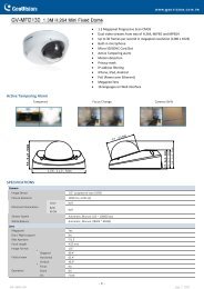
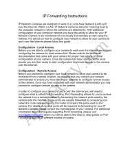
AppendixDI/DO Input SpecificationsPin 1 Pin 4Pin 2Pin 3PIN FUNCTION NOTE1 Digital Out (DO) Uses an open-drain NFET transistor with the source connected to GND in camera. If usedwith an external relay, a diode must be connected in parallel with the load for protectionagainst voltage transients. Max loading is 100 mA.2 Digital In (DI) A switch from DI to DC 5 V, activated by setting NO. or NC.3 DC5V OUTPUT DC 5 V Output / Max. 100 mA4 GND GNDInternal 5V PowerDNDExternal 3~12V PowerDNDDC Power 5VDC Power 5V5V5VDC Power 3V~12VN.C / N.ODIReed switchN.C / N.ODIReed switchRR100 mADODiode100 mADODiodeALARMALARMD-<strong>Link</strong> DCS-2210/2230 User Manual56
AppendixTechnical SpecificationsCameraCamera HardwareProfileImage FeaturesVideo CompressionVideo ResolutionAudio Support G.726External DeviceInterface1/2.7” 2 Megapixel progressive CMOS sensorIR illumination distance: 5 mMinimum illumination 0 lux with IR illuminationBuilt-in Infrared-Cut Removable (ICR)lter moduleBuilt-in PIR sensorBuilt-in microphone and speaker10x digital zoomFixed length 4.37 mmConfigurable image size, quality, frame rate, and bit rateTime stamp and text overlaysConfigurable motion detection windowsSimultaneous H.264/MPEG-4/MJPEG format compressionJPEG for still imageH.264/MPEG-4 multicast streamingAperture F2.0Angle of view:(H) 67.4°(V) 40.8°(D) 75°3 configurable privacy mask zonesConfigurable shutter speed, brightness, saturation, contrast,and sharpness16:9 - 1920 x 1080 (up to 15 fps), 1280 x 720, 800 x 450, 640 x 360, 480 x 270, 320 x 176, 176 x 144 up to 30 fps4:3 - 1440 x 1080 (up to 15 fps), 1280 x 960, 1024 x 768, 800 x 600, 640 x 480, 320 x 240, 176 x 144 up to 30 fps1 DI / 1 DOMicro SD card slotNetwork Network Protocols IPv4, TCP/IP, UDP, ICMP, DHCP Client, NTP Client (D-<strong>Link</strong>), DNS Client, DDNS Client (D-<strong>Link</strong>), SMTP Client, FTP Client, HTTP / HTTPS,Samba Client, PPPoE, UPnP Port Forwarding, RTP / RTSP/ RTCP, IP filtering, 3GPP, IGMP, ONVIF CompliantSecurityAdministrator and user group protectionPassword authenticationHTTP and RTSP digest encryptionD-<strong>Link</strong> DCS-2210/2230 User Manual57
AppendixTechnical SpecificationsSystemManagementSystemRequirements forWeb InterfaceEvent ManagementRemoteManagementMobile SupportD-ViewCam SystemRequirementsD-ViewCamSoftware FunctionsOperating System: Microsoft Windows 7/Vista/XP/2000Browser: Internet Explorer, Firefox, Netscape, OperaMotion detectionEvent notification and upload snapshots/video clips via HTTP,SMTP, or FTPConfiguration accessible via web browserTake snapshots/video clips and save to local hard drive or NAS via web browserWindows 7/Vista/XP system, Pocket PC, or mobile phone with 3GPP playback supportOperating System: Microsoft Windows 7/Vista/XPWeb Browser: Internet Explorer 6 or higherRemote management/control of up to 32 camerasViewing of up to 32 cameras on one screenGeneral Power Input 5 V DC 1.2 A, 50/60 Hz, PoE ( DCS-2210 only )Max. PowerConsumptionOperatingTemperatureStorageTemperatureHumidityWeightCertificationsDCS-2210: 3.5 wattsDCS-2230: 4 watts0 to 40 ˚C (32 to 104 ˚F)-20 to 70 °C (-4 to 158 °F)20% to 80% non-condensingDCS-2210: 80 gDCS-2230: 75 gCE, CE LVD, FCC(Class B), C-Tick* This device complies with part 15 of the FCC Rules.Operation is subject to the following two conditions:(1) This device may not cause harmful interference.(2) This device must accept any interference received, including interference that may cause undesired operation.Supports multiple HTTP, SMTP, and FTP serversMultiple event notificationsMultiple recording methods for easy backupProtocol: Standard TCP/IPSupports all management functions provided in web interfaceScheduled motion triggered, or manual recording optionsD-<strong>Link</strong> DCS-2210/2230 User Manual58
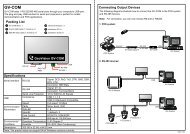
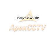
AppendixDCS-2210/2230Dimensions9738.75882.3128.69582D-<strong>Link</strong> DCS-2210/2230 User Manual59
Contacting Technical SupportContacting Technical SupportU.S. and Canadian customers can contact D-<strong>Link</strong> technical support through our web site or by phone.Before you contact technical support, please have the following ready:• Model number of the product (e.g. DCS-2210/2230)• Hardware Revision (located on the label on the bottom of the Network Camera (e.g. rev A1))• Serial Number (s/n number located on the label on the bottom of the Network Camera).You can find software updates and user documentation on the D-<strong>Link</strong> website as well as frequently asked questions andanswers to technical issues.For customers within the United States:Phone Support:(877) 354-6555Internet Support:http://support.dlink.comFor customers within Canada:Phone Support:(800) 354-6560Internet Support:http://support.dlink.caD-<strong>Link</strong> DCS-2210/2230 User Manual60
WarrantyWarrantySubject to the terms and conditions set forth herein, D-<strong>Link</strong> Systems, Inc. (“D-<strong>Link</strong>”) provides this Limited Warranty:• Only to the person or entity that originally purchased the product from D-<strong>Link</strong> or its authorized reseller or distributor, and• Only for products purchased and delivered within the fifty states of the United States, the District of Columbia, U.S. Possessionsor Protectorates, U.S. Military Installations, or addresses with an APO or FPO.Limited Warranty:D-<strong>Link</strong> warrants that the hardware portion of the D-<strong>Link</strong> product described below (“Hardware”) will be free from material defects in workmanshipand materials under normal use from the date of original retail purchase of the product, for the period set forth below (“Warranty Period”), exceptas otherwise stated herein.• Hardware (excluding power supplies and fans): One (1) year• Power supplies and fans: One (1) year• Spare parts and spare kits: Ninety (90) daysThe customer’s sole and exclusive remedy and the entire liability of D-<strong>Link</strong> and its suppliers under this Limited Warranty will be, atD-<strong>Link</strong>’s option, to repair or replace the defective Hardware during the Warranty Period at no charge to the original owner or to refund the actualpurchase price paid. Any repair or replacement will be rendered by D-<strong>Link</strong> at an Authorized D-<strong>Link</strong> Service Office. The replacement hardwareneed not be new or have an identical make, model or part. D-<strong>Link</strong> may, at its option, replace the defective Hardware or any part thereof with anyreconditioned product that D-<strong>Link</strong> reasonably determines is substantially equivalent (or superior) in all material respects to the defective Hardware.Repaired or replacement hardware will be warranted for the remainder of the original Warranty Period or ninety (90) days, whichever is longer,and is subject to the same limitations and exclusions. If a material defect is incapable of correction, or if D-<strong>Link</strong> determines that it is not practicalto repair or replace the defective Hardware, the actual price paid by the original purchaser for the defective Hardware will be refunded by D-<strong>Link</strong>upon return to D-<strong>Link</strong> of the defective Hardware. All Hardware or part thereof that is replaced by D-<strong>Link</strong>, or for which the purchase price is refunded,shall become the property of D-<strong>Link</strong> upon replacement or refund.D-<strong>Link</strong> DCS-2210/2230 User Manual61
WarrantyLimited Software Warranty:D-<strong>Link</strong> warrants that the software portion of the product (“Software”) will substantially conform to D-<strong>Link</strong>’s then current functional specificationsfor the Software, as set forth in the applicable documentation, from the date of original retail purchase of the Software for a period of ninety (90)days (“Software Warranty Period”), provided that the Software is properly installed on approved hardware and operated as contemplated in itsdocumentation. D-<strong>Link</strong> further warrants that, during the Software Warranty Period, the magnetic media on which D-<strong>Link</strong> delivers the Software willbe free of physical defects. The customer’s sole and exclusive remedy and the entire liability of D-<strong>Link</strong> and its suppliers under this Limited Warrantywill be, at D-<strong>Link</strong>’s option, to replace the non-conforming Software (or defective media) with software that substantially conforms to D-<strong>Link</strong>’sfunctional specifications for the Software or to refund the portion of the actual purchase price paid that is attributable to the Software. Except asotherwise agreed by D<strong>Link</strong> in writing, the replacement Software is provided only to the original licensee, and is subject to the terms and conditionsof the license granted by D-<strong>Link</strong> for the Software. Replacement Software will be warranted for the remainder of the original Warranty Period and issubject to the same limitations and exclusions. If a material non-conformance is incapable of correction, or if D-<strong>Link</strong> determines in its sole discretionthat it is not practical to replace the non-conforming Software, the price paid by the original licensee for the non-conforming Software will berefunded by D-<strong>Link</strong>; provided that the non-conforming Software (and all copies thereof) is first returned to D-<strong>Link</strong>. The license granted respectingany Software for which a refund is given automatically terminates.Non-Applicability of Warranty:The Limited Warranty provided hereunder for Hardware and Software portions of D-<strong>Link</strong>’s products will not be applied to and does not cover anyrefurbished product and any product purchased through the inventory clearance or liquidation sale or other sales in which D-<strong>Link</strong>, the sellers, orthe liquidators expressly disclaim their warranty obligation pertaining to the product and in that case, the product is being sold “As-Is” without anywarranty whatsoever including, without limitation, the Limited Warranty as described herein, notwithstanding anything stated herein to the contrary.Submitting A Claim:The customer shall return the product to the original purchase point based on its return policy. In case the return policy period has expired and theproduct is within warranty, the customer shall submit a claim to D-<strong>Link</strong> as outlined below:• The customer must submit with the product as part of the claim a written description of the Hardware defect or Softwarenonconformance in sufficient detail to allow D-<strong>Link</strong> to confirm the same, along with proof of purchase of the product (such as acopy of the dated purchase invoice for the product) if the product is not registered.• The customer must obtain a Case ID Number from D-<strong>Link</strong> Technical Support (USA 1-877-453-5465 or Canada 1-800-361-5265), whowill attempt to assist the customer in resolving any suspected defects with the product. If the product is considered defective, thecustomer must obtain a Return Material Authorization (“RMA”) number by completing the RMA form. Enter the assigned Case IDNumber at https://rma.dlink.com/ (USA only) or https://rma.dlink.ca (Canada only).D-<strong>Link</strong> DCS-2210/2230 User Manual62
Warranty• After an RMA number is issued, the defective product must be packaged securely in the original or other suitable shipping packageo ensure that it will not be damaged in transit, and the RMA number must be prominently marked on the outside of the package.Do not include any manuals or accessories in the shipping package. D-<strong>Link</strong> will only replace the defective portion of the productand will not ship back any accessories.• The customer is responsible for all in-bound shipping charges to D-<strong>Link</strong>. No Cash on Delivery (“COD”) is allowed. Products sent CODwill either be rejected by D-<strong>Link</strong> or become the property of D-<strong>Link</strong>. Products shall be fully insured by the customer and shippedto D-<strong>Link</strong> Systems, Inc.• USA residents send to 17595 Mt. Herrmann, Fountain Valley, CA 92708. D-<strong>Link</strong> will not be held responsible for any packages thatare lost in transit to D-<strong>Link</strong>. The repaired or replaced packages will be shipped to the customer via UPS Ground or any commoncarrier selected by D-<strong>Link</strong>. Return shipping charges shall be prepaid by D-<strong>Link</strong> if you use an address in the United States, otherwisewe will ship the product to you freight collect. Expedited shipping is available upon request and provided shipping charges areprepaid by the customer. D-<strong>Link</strong> may reject or return any product that is not packaged and shipped in strict compliance with theforegoing requirements, or for which an RMA number is not visible from the outside of the package. The product owner agrees topay D-<strong>Link</strong>’s reasonable handling and return shipping charges for any product that is not packaged and shipped in accordancewith the foregoing requirements, or that is determined by D-<strong>Link</strong> not to be defective or non-conforming.• Canadian residents send to D-<strong>Link</strong> Networks, Inc., 2525 Meadowvale Boulevard Mississauga, Ontario, L5N 5S2 Canada. D-<strong>Link</strong> willnot be held responsible for any packages that are lost in transit to D-<strong>Link</strong>. The repaired or replaced packages will be shipped tothe customer via Purolator Canada or any common carrier selected by D-<strong>Link</strong>. Return shipping charges shall be prepaid by D-<strong>Link</strong>if you use an address in Canada, otherwise we will ship the product to you freight collect. Expedited shipping is available uponrequest and provided shipping charges are prepaid by the customer. D-<strong>Link</strong> may reject or return any product that is not packagedand shipped in strict compliance with the foregoing requirements, or for which an RMA number is not visible from the outside ofthe package. The product owner agrees to pay D-<strong>Link</strong>’s reasonable handling and return shipping charges for any product that isnot packaged and shipped in accordance with the foregoing requirements, or that is determined by D-<strong>Link</strong> not to be defective ornon-conforming. RMA phone number: 1-800-361-5265 Hours of Operation: Monday-Friday, 9:00AM – 9:00PM EST.What Is Not Covered:The Limited Warranty provided herein by D-<strong>Link</strong> does not cover:Products that, in D-<strong>Link</strong>’s judgment, have been subjected to abuse, accident, alteration, modification, tampering, negligence, misuse, faulty installation,lack of reasonable care, repair or service in any way that is not contemplated in the documentation for the product, or if the model or serial numberhas been altered, tampered with, defaced or removed; Initial installation, installation and removal of the product for repair, and shipping costs;Operational adjustments covered in the operating manual for the product, and normal maintenance; Damage that occurs in shipment, due to actof God, failures due to power surge, and cosmetic damage; Any hardware, software, firmware or other products or services provided by anyoneother than D-<strong>Link</strong>; and Products that have been purchased from inventory clearance or liquidation sales or other sales in which D-<strong>Link</strong>, the sellers,D-<strong>Link</strong> DCS-2210/2230 User Manual63
Warrantyor the liquidators expressly disclaim their warranty obligation pertaining to the product.While necessary maintenance or repairs on your Product can be performed by any company, we recommend that you use only an Authorized D-<strong>Link</strong>Service Office. Improper or incorrectly performed maintenance or repair voids this Limited Warranty.Disclaimer of Other Warranties:EXCEPT FOR THE LIMITED WARRANTY SPECIFIED HEREIN, THE PRODUCT IS PROVIDED “AS-IS” WITHOUT ANY WARRANTY OF ANY KIND WHATSOEVERINCLUDING, WITHOUT LIMITATION, ANY WARRANTY OF MERCHANTABILITY, FITNESS FOR A PARTICULAR PURPOSE AND NONINFRINGEMENT.IF ANY IMPLIED WARRANTY CANNOT BE DISCLAIMED IN ANY TERRITORY WHERE A PRODUCT IS SOLD, THE DURATION OF SUCH IMPLIED WARRANTYSHALL BE LIMITED TO THE DURATION OF THE APPLICABLE WARRANTY PERIOD SET FORTH ABOVE. EXCEPT AS EXPRESSLY COVERED UNDER THELIMITED WARRANTY PROVIDED HEREIN, THE ENTIRE RISK AS TO THE QUALITY, SELECTION AND PERFORMANCE OF THE PRODUCT IS WITH THEPURCHASER OF THE PRODUCT.Limitation of Liability:TO THE MAXIMUM EXTENT PERMITTED BY LAW, D-LINK IS NOT LIABLE UNDER ANY CONTRACT, NEGLIGENCE, STRICT LIABILITY OR OTHER LEGALOR EQUITABLE THEORY FOR ANY LOSS OF USE OF THE PRODUCT, INCONVENIENCE OR DAMAGES OF ANY CHARACTER, WHETHER DIRECT, SPECIAL,INCIDENTAL OR CONSEQUENTIAL (INCLUDING, BUT NOT LIMITED TO, DAMAGES FOR LOSS OF GOODWILL, LOSS OF REVENUE OR PROFIT, WORKSTOPPAGE, COMPUTER FAILURE OR MALFUNCTION, FAILURE OF OTHER EQUIPMENT OR COMPUTER PROGRAMS TO WHICH D-LINK’S PRODUCTIS CONNECTED WITH, LOSS OF INFORMATION OR DATA CONTAINED IN, STORED ON, OR INTEGRATED WITH ANY PRODUCT RETURNED TO D-LINKFOR WARRANTY SERVICE) RESULTING FROM THE USE OF THE PRODUCT, RELATING TO WARRANTY SERVICE, OR ARISING OUT OF ANY BREACH OFTHIS LIMITED WARRANTY, EVEN IF D-LINK HAS BEEN ADVISED OF THE POSSIBILITY OF SUCH DAMAGES. THE SOLE REMEDY FOR A BREACH OFTHE FOREGOING LIMITED WARRANTY IS REPAIR, REPLACEMENT OR REFUND OF THE DEFECTIVE OR NONCONFORMING PRODUCT. THE MAXIMUMLIABILITY OF D-LINK UNDER THIS WARRANTY IS LIMITED TO THE PURCHASE PRICE OF THE PRODUCT COVERED BY THE WARRANTY. THE FOREGOINGEXPRESS WRITTEN WARRANTIES AND REMEDIES ARE EXCLUSIVE AND ARE IN LIEU OF ANY OTHER WARRANTIES OR REMEDIES, EXPRESS, IMPLIEDOR STATUTORY.Governing Law:This Limited Warranty shall be governed by the laws of the State of California. Some states do not allow exclusion or limitation of incidental orconsequential damages, or limitations on how long an implied warranty lasts, so the foregoing limitations and exclusions may not apply. ThisLimited Warranty provides specific legal rights and you may also have other rights which vary from state to state.Trademarks:D-<strong>Link</strong> is a registered trademark of D-<strong>Link</strong> Corporation/D-<strong>Link</strong> Systems, Inc. Other trademarks or registered trademarks are the property of theirrespective owners.D-<strong>Link</strong> DCS-2210/2230 User Manual64
WarrantyCopyright Statement:No part of this publication or documentation accompanying this product may be reproduced in any form or by any means or used to make anyderivative such as translation, transformation, or adaptation without permission from D-<strong>Link</strong> Corporation/D-<strong>Link</strong> Systems, Inc., as stipulated by theUnited States Copyright Act of 1976 and any amendments thereto. Contents are subject to change without prior notice.Copyright ©2011 by D-<strong>Link</strong> Corporation/D-<strong>Link</strong> Systems, Inc. All rights reserved.CE Mark Warning:This is a Class B product. In a domestic environment, this product may cause radio interference, in which case the user may be required to takeadequate measures.FCC Statement:This equipment has been tested and found to comply with the limits for a Class B digital device, pursuant to part 15 of the FCC Rules. These limits aredesigned to provide reasonable protection against harmful interference in a residential installation. This equipment generates, uses, and can radiateradio frequency energy and, if not installed and used in accordance with the instructions, may cause harmful interference to radio communication.However, there is no guarantee that interference will not occur in a particular installation. If this equipment does cause harmful interference to radioor television reception, which can be determined by turning the equipment off and on, the user is encouraged to try to correct the interferenceby one or more of thefollowing measures:• Reorient or relocate the receiving antenna.• Increase the separation between the equipment and receiver.• Connect the equipment into an outlet on a circuit different from that to which the receiver is connected.• Consult the dealer or an experienced radio/TV technician for help.FCC Caution:Any changes or modifications not expressly approved by the party responsible for compliance could void the user’s authority to operate thisequipment.This device complies with Part 15 of the FCC Rules. Operation is subject to the following two conditions:(1) This device may not cause harmful interference, and (2) this device must accept any interference received, including interference that may causeundesired operation.D-<strong>Link</strong> DCS-2210/2230 User Manual65
WarrantyIf this device is going to be operated in 5.15 ~ 5.25GHz frequency range, then it is restricted in indoor environment only.IMPORTANT NOTICE:FCC Radiation Exposure Statement:This equipment complies with FCC radiation exposure limits set forth for an uncontrolled environment. This equipment should be installed andoperated with minimum distance 20cm between the radiator & your body. This transmitter must not be co-located or operating in conjunctionwith any other antenna or transmitter.The availability of some specific channels and/or operational frequency bands are country dependent and are firmware programmed at the factoryto match the intended destination. The firmware setting is not accessible by the end user.For detailed warranty information applicable to products purchased outside the United States, please contact the corresponding local D-<strong>Link</strong>office.Industry Canada Notice:This device complies with RSS-210 of the Industry Canada Rules. Operation is subject to the following two conditions:(1) This device may not cause harmful interference, and (2) this device must accept any interference received, including interference that may causeundesired operation.IMPORTANT NOTE:Radiation Exposure Statement:This equipment complies with IC radiation exposure limits set forth for an uncontrolled environment. This equipment should be installed andoperated with minimum distance 20cm between the radiator & your body.This device has been designed to operate with an antenna having a maximum gain of 2 dB. Antenna having a higher gain is strictly prohibited perregulations of Industry Canada. The required antenna impedance is 50 ohms.D-<strong>Link</strong> DCS-2210/2230 User Manual66
RegistrationRegistrationProduct registration is entirely voluntary and failure to complete or return this form will not diminish your warranty rights.Version 1.0October 13, 2011D-<strong>Link</strong> DCS-2210/2230 User Manual67