HUNTER-PRO SERIES SA - Pima Electronic Systems Ltd
HUNTER-PRO SERIES SA - Pima Electronic Systems Ltd
HUNTER-PRO SERIES SA - Pima Electronic Systems Ltd

Create successful ePaper yourself
Turn your PDF publications into a flip-book with our unique Google optimized e-Paper software.
<strong>HUNTER</strong>-<strong>PRO</strong> <strong>SERIES</strong> <strong>SA</strong>Models 832/896/8144ALARM SYSTEMSUSER GUIDEThe LED’S in all PIMA keypads are:RED: ARMED GREEN: FAULTPIMA <strong>Electronic</strong> <strong>Systems</strong> <strong>Ltd</strong>.www.pima-alarms.comP/N 4410298 AZA, en, June 2011
2 Hunter-Pro Series - User GuideLimited WarrantyPIMA <strong>Electronic</strong> <strong>Systems</strong> <strong>Ltd</strong>. does not represent that its Product may not be compromised and/orcircumvented, or that the Product will prevent any death, personal and/or bodily injury and/or damage toproperty resulting from burglary, robbery, fire or otherwise, or that the Product will in all cases provideadequate warning or protection. The User understands that a properly installed and maintained equipmentmay only reduce the risk of events such as burglary, robbery, and fire without warning, but it is notinsurance or a guarantee that such will not occur or that there will be no death, personal damage and/ordamage to property as a result.PIMA <strong>Electronic</strong> <strong>Systems</strong> <strong>Ltd</strong>. shall have no liability for any death, personal and/or bodily injuryand/or damage to property or other loss whether direct, indirect, incidental, consequential orotherwise, based on a claim that the Product failed to function.Please refer to a separate warranty statement found on PIMA website at:http://www.pima-alarms.com/site/Content/t1.asp?pid=472&sid=57Warning: The user should follow the installation and operation instructions and among other things testthe Product and the whole system at least once a week. For various reasons, including, but not limited to,changes in environment conditions, electric or electronic disruptions and tampering, the Product may notperform as expected. The user is advised to take all necessary precautions for his/her safety and theprotection of his/her property.This document may not be duplicated, circulated, altered, modified, translated, reduced to any form orotherwise changed, unless PIMA’s prior written consent is granted.All efforts have been made to ensure that the content of this manual is accurate. <strong>Pima</strong> retains the right tomodify this manual or any part thereof, from time to time, without serving any prior notice of suchmodification.Please read this manual in its entirety before attempting to program or operate your system. Should youmisunderstand any part of this manual, please contact the supplier or installer of this system.Copyright 2011 PIMA <strong>Electronic</strong> <strong>Systems</strong> <strong>Ltd</strong>. All rights reserved.Contact us:PIMA <strong>Electronic</strong> <strong>Systems</strong> <strong>Ltd</strong>.5 Hatzoref Street, Holon 58856, IsraelTel: +972.3.6506414Fax: +972.3.5500442Email: support@pima-alarms.comWeb: http://www.pima-alarms.comPIMA Alarm <strong>Systems</strong> <strong>Ltd</strong>.
Hunter-Pro Series - User Guide 3TABLE OF CONTENTS1. Introduction ...................................................................................... 51.1 Safety instructions .................................................................................. 51.2 Main Features ......................................................................................... 51.3 Signs in this guide and codes .................................................................... 61.3.1 Codes ..................................................................................................... 61.4 Partitioned system .................................................................................. 61.4.1 Programming Partitions ............................................................................. 61.5 The User menu ....................................................................................... 71.6 The LCD keypad ...................................................................................... 71.6.1 The keypad keys & functions ...................................................................... 82. Key #1: Arming & Disarming ............................................................... 92.1 The arming procedure .............................................................................. 92.1.1 Arming with the Master code .................................................................... 102.1.2 Arming with Short code or authorized User code ......................................... 102.1.3 Single keystroke arming .......................................................................... 102.2 Arming with open zones ......................................................................... 102.3 Arming using a key, key fob, or RFID accessory ........................................ 112.3.1 Key ....................................................................................................... 112.3.2 Key fobs ................................................................................................ 112.3.3 RFID accessory ...................................................................................... 122.4 Disarming ............................................................................................ 122.4.1 Disarming with the Duress code ............................................................... 123. Key #2: The Memory Log .................................................................. 124. Key #3: Temporary Zone Bypassing ................................................... 135. Keys #4, #7: Arming to “HOME 1” and “HOME 2” Modes ...................... 146. Key #5: Displaying Types ................................................................. 156.1 Fast zone display .................................................................................. 156.1.1 The displayed information ........................................................................ 156.2 „Scan Open Zones‟ auto-scrolling display type ........................................... 166.3 Other display types ............................................................................... 166.3.1 All Zones Status Display .......................................................................... 177. Key #6: Telephone Numbers, SMS Settings & Dialer Test ..................... 177.1 Edit telephone numbers ......................................................................... 177.2 SMS phone settings ............................................................................... 187.3 Dialer test ............................................................................................ 188. Key #8: Time and Date .................................................................... 199. Key #9: Codes & User Settings .......................................................... 199.1 Master Code ......................................................................................... 199.1.1 Changing the Master code ....................................................................... 209.2 User Codes ........................................................................................... 209.2.1 Add a new or change a User code ............................................................. 209.2.2 Deleting a User code ............................................................................... 219.3 The Duress code ................................................................................... 219.4 The Short code ..................................................................................... 219.5 The Door code ...................................................................................... 219.6 The User name ..................................................................................... 219.7 User settings ........................................................................................ 229.8 Disarming time window .......................................................................... 229.9 User partitions ...................................................................................... 23PIMA Alarm <strong>Systems</strong> <strong>Ltd</strong>.
Hunter-Pro Series - User Guide 51. INTRODUCTIONCongratulations on your purchase of the Hunter-Pro Series intruder alarm system. Much carehas been taken in developing the series. The system with its advanced features willprofessionally help you to protect your premises or business.The Hunter-Pro Series has numerous features that allow it to befit your individual needs, andyet remain easy to program and use. It is important to read this guide thoroughly in order tofamiliarize yourself with the system and take full advantage of its features. To assure optimalsafety and security, you should perform a system test at least once a week (see instructions onsection 10).For any further questions, please contact your local PIMA distributor.Up to date literature is available to download from our website at: www.pima-alarms.com1.1 Safety instructionsYour Hunter-Pro Series alarm system has been registered in accordance with EN60950 and its rules. EN60950 requires us to advise you the following information:1. In this alarm system exist hazards of fire and electric shock. To reduce the risk of fire or electricshock, do not expose this alarm system to rain or moisture. Pay attention: Telephone cordscould be a good conductor for lightings energy.2. Do not open the door of the alarm system. Dangerous high voltages are present inside of theenclosure. Refer servicing to qualified personnel only.3. This alarm system should be used with AC 230V50Hz, protected by anti electric shock breaker.To prevent electric shocks and fire hazards, do NOT use any other power source.4. Do not spill liquid of any kind onto the unit. If liquid is accidentally spilled onto the unit,immediately consult a qualified service.5. Install this product in a protected location where no one can trip over any line or power cord.Protect cords from damage or abrasion.6. Disconnect all sources of power supply before proceeding with the installation. Pay attention:do not install low voltage wires near AC power wires; they should be separated.7. Connect the AC transformer output to the terminal block on the control panel as marked.8. Connect the AC line cord to line power terminals as marked. (GND; N; L)1.2 Main Features• Hybrid system with 8 to 32/96/144 hardwired or wireless zones (depending on your model);• Fast arming functions;• Partitioned system. See the next section• Arming options:Full, for interior and perimeter;“Home 1/Home 2”, for arming of some zone while others are not;Passive, for auto-arming after a preset silence (no movement) time;Automatic, at a preset time by day of the week;• You cannot arm the system unless all the zones are closed or were previously programmedto be bypassed;• The system can be remote controlled via a Touch-tone telephone;PIMA Alarm <strong>Systems</strong> <strong>Ltd</strong>.
6 Hunter-Pro Series - User Guide• Codes (depending on your model): 32/96/144 user codes, RFID tags/key chains, 24remote control codes;• Various authorization levels per user;• Window time to restrict users from disarming the system;• Extensive zone testing;• 2 basic displaying types to view the system status: “Fast display” and “Scan Open Zones”.Other types support various features;• Integrated 4 digital channels for communicating with the Central Monitoring Station:Telephone, FSK/RDC Radio, GSM, GPRS;• Full supervision data of wireless detectors for low battery, tamper switches, etc.;• Support in key zones, that allows arming with the use of a key.• Support in KE wireless transceivers and key fobs;• 4 Subscriber dialing numbers with optional voice message/microphone;• Various methods to prevent false alarms and tampering: Zone conditioning, pulse counter,EOL resistor loops, zone sensitivity, automatic zone deactivating, zone soaking;• Memory Log of up to 500/998 entries (of which 250/500 are non-volatile, even after reset)that includes time stamp, username, zone name and more.1.3 Signs in this guide and codes Press a key Hold a key for 3 seconds or until confirmation “beep” is sounded1.3.1 CodesMaster code: a super user code with all user authorizations;User code: a code given per user with different authorizations;1.4 Partitioned systemPartitions are used when the premises is logically or physically divided, e.g., to differentparts of the house, several offices sharing the same alarm system, or for use in a group ofbuildings.• You can use up to 16 partitions, each with its own account and users. Keypads can beshared to all the partitions, or be limited to some.;• Otherwise, you can set up to 8 keypads to be used separately, in separated zones,displaying only information from their allocated zones and be operated only by theirallocated users. These can be referred to as sub-systems.1.4.1 Programming PartitionsIn the User menu, partitions are programmed in a 2-state parameter bar, where “+” isenabled and “-” is disabled. To change the state of a parameter/partition, # (toggle).PIMA Alarm <strong>Systems</strong> <strong>Ltd</strong>.
Hunter-Pro Series - User Guide 7In the next example, partitions 1,2,9,10 are enabled for User1, while other partitionsare disabled.Part. For User1++----++--------1 2 3 4 5 6 7 8 9 10 11 12 13 14 15 161.5 The User menuThe User menu is where the user program data such as time & date, telephone numbers,codes and user settings.The User menu can be fully accessed with the Master Code. Users with appropriateauthorizations can also access the user menu, but can be limited from programmingcertain information, as well as be limited to use certain keypads or zones.Set globally by the Installer, entering a User code may either fully arm (Away mode) ordisarm the panel (toggle mode), or display the User menu. To access the User menu:1. Master code/Authorized User code -OR-2. Authorized User codeThe sub-menus are accessed directly by pressing one of the keypad keys. Each key has itsaction printed above it.When a user tries to enter a sub-menu it is not authorized to:1.6 The LCD keypadAccess Denied!Press ENDThe RXN-400 and RXN-410 (including the RFID model) are PIMA‟s LCD (Liquid CrystalDisplay) keypads.The two models are identical, except for their screen size - the RXN-410‟s is larger.1. Up to 8 keypads can be connected to the system.User MenuSelect 1,2...2. When one of the keypad is in programming mode or when the system isremotely controlled, the key pad is disabled and he message “Other Keypadin Use” is displayed.PIMA Alarm <strong>Systems</strong> <strong>Ltd</strong>.
10 Hunter-Pro Series - User GuideWhen the countdown ends, the ARMED LED illuminates, the beeps stop, the message“System Armed” is displayed for a few seconds and then the date and time are displayed.2.1.1 Arming with the Master code Master code System Armed!User MenuSelect 1,2... 1ON/OFFArming...Exit Delay 45 . . . .2.1.2 Arming with Short code or authorized User code Short code or authorized User code 2.1.3 Single keystroke armingSingle keystroke arming is a feature that must be enabled by the installer.It allows you to arm the system with a single long keystroke, without having to enter anycode.Disarming, on the other hand, always requires to enter a valid code.The single keystroke options are:• Full Arming: • Arming to “„Home 1” mode: • Arming to “Home 2” mode: 2.2 Arming with open zonesZones cannot be bypassed during the arming procedure, i.e., they must be bypassed priorto arming. See section 4 for details.When trying to arm with open zones (other than delayed zones), the keypad sounds beepsand the message “Open Zone! Press END” is displayed with the open zones („Front door‟ inthe next example), in 2 alternating screens:Open Zone! Press ENDOP:Front door ~ OP:Front1To cancel the arming: END47User MenuSelect 1,2... 1doorON/OFFIf you do not press [END], the panel will indeed be armed, but alarms will be generatedfrom the open zones immediately after the exit delay ends.PIMA Alarm <strong>Systems</strong> <strong>Ltd</strong>.
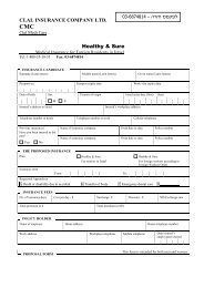
Hunter-Pro Series - User Guide 112.3 Arming using a key, key fob, or RFID accessory2.3.1 KeyThe system can be armed to full, “Home 1” and “Home 2” modes, and be disarmed, usinga key switch. The switch can be momentary (toggle) or ON/OFF one.In addition to that, any zone can be set as a key zone and be used for the same purposes.This enables you to arm the system per partition (see section 1.4), e.g., to arm the perimeterwhile the interior is disarmed.2.3.2 Key fobsYou can perform several operations using a key fob: full arming, disarming, arming to“HOME 1” and “HOME 2” modes, generating a Panic alert and triggering an output, foractivating an electric gate, for example. up to 24 Visonic/KE key fobs can be used withyour alarm system.A key fob is given per user and is restricted according to the user authorizations.The Visonic MCT-234 key fob has 4 push buttons. See the next figure for theirfunctionality.Note, that to use a key fob you need a wireless module, like <strong>Pima</strong>‟s I/O-WN.Figure 2.Visonic MCT-234 key fobFigure 3.Other key fobsThe key fobs functions in relation to their buttons are:Button 1: Full arm (Away), Red LED on;Button 2: Disarm, Red LED off;Button 1 + Button 2: Hold together to operate the PANIC;Button 3: HOME1 mode arm, Red/Green LED‟s on; hold the button for longer than 2seconds to arm to HOME2 mode, Green LED on;Button 4: Operate the on board Relay.PIMA Alarm <strong>Systems</strong> <strong>Ltd</strong>.
Hunter-Pro Series - User Guide 156. KEY #5: DISPLAYING TYPESThere are 2 basic displaying types in the LCD keypads: fast, 32 zone display, and autoscrollingmode that includes open zones and faults.Other types are used for displaying various information for a minute, before they return toone of the basic types, except for the “Display partitions”. See further.6.1 Fast zone display Master code Dispaly type:Fast Zn. DisplayThis display type is best used in an up to 32 zone system: the status of all the 32 zones isdisplayed in a single screen. See the next screenshot.Each zone status is displayed next to its number, printed around the keypad‟s screen.17 18 19 20 21 22 23 24 25 26 27 28 29 30 31 32----_--___-BB---C-C-__---F------1 2 3 4 5 6 7 8 9 10 11 12 13 14 15 16In this example, zones 1,3 are chime zones (see the next table), zones 5,6,21,24-26 areopen, etc.When a fault occurs, the zone status is concealed until the fault is being cared.When no more than 16 zones are set, the time, date and system status are displayed intop line. See the next example.6.1.1 The displayed informationDate System indicatorsZone number 17 18 19 20 21 22 23 24 25 26 27 28 29 30 31 328 NOV 11PS05:23Zone/Partition numberFigure 4.The system indicators on the top line are:IndicatorPSRC-C-__---F------1 2 3 4 5 6 7 8 9 10 11 12 13 14 15 16Zone status indicators16 zone, Fast display type exampleDescriptionThe system is communicating or testing the telephone lineThe on board SIREN output is activatedThe on board RELAY output is activatedThe zone status indicators are:TimeIndicator Description- Closed and ready to arm zone_ Open (violated) and not ready to arm zoneA Alarming zone. This zone was violated the last time the system was armed,or it is a 24 Hour zone.B This zone will be bypassed the next time the system will be armedC Chime zonePIMA Alarm <strong>Systems</strong> <strong>Ltd</strong>.
16 Hunter-Pro Series - User GuideIndicator DescriptionF Zone failure or an open tamper switch in a wireless detectorL Low battery in a wireless detector. Replace battery!O 24 hour zone or armed partition. # to display armed partitions.S Zone cutT Zone is in soak mode (i.e. will not sound the alarm if violated, but is logged)V A wireless detector is not reporting6.2 „Scan Open Zones‟ auto-scrolling display typeIn „Scan Open Zones‟ display, open zones, faults and alarms are displayed in an autoscrollingmode.Date15 MAY 11S 01:20Voltage~FaultSystem indicatorsIndicatorFigure 5.15 MAY 11 P01:20OP:Warehouse 5Zone nameThe upper line is described in the previous section.Indicators in the bottom line are:IndicatorOPALSH,SV,FLLBDescriptionOpen zoneZone alarmZone failuresLow battery in a wireless detectorTime~Scan Open Zones type exampleZone names are programmed by the technician15 MAY 11SP01:20LB:Back yard6.3 Other display typesThe system displays various status information described in the next table. Each status isdisplayed for one minute.Press Display type Description Master codeNEXTNEXTNEXTNEXTNEXTNEXTX3X4X5X6X7User MenuSelect 1,2...All zonesDisplay Bypassed ZonesZonesDisplay Soaked ZonesDisplay Chime ZonesAll Zones StatusTheShow Partitions Names5Zone details: number, name, partitions & typethat will be bypassed the next time the systemis armedZones in soak modeChime zonesFast 32 zone display, extended to all the zones; see thenext section.The partitions (i.e. the allocated zones) that are operatedby this keypadPIMA Alarm <strong>Systems</strong> <strong>Ltd</strong>.
Hunter-Pro Series - User Guide 176.3.1 All Zones Status Display17 18 19 20 21 22 23 24 25 26 27 28 29 30 31 32C--___BB-- 1->10-F--S_---- 11->201 2 3 4 5 6 7 8 9 10 11 12 13 14 15 16NEXTZones17 18 19 20 21 22 23 24 25 26 27 28 29 30 31 32--C----C--21->30-__--B---_31->401 2 3 4 5 6 7 8 9 10 11 12 13 14 15 16.…NEXT17 18 19 20 21 22 23 24 25 26 27 28 29 30 31 32-_-- 144>1 2 3 4 5 6 7 8 9 10 11 12 13 14 15 16The Fast 32 zone display, extended to all the zones. The zones are displayed 10 per line,20 per screen. NEXT or BACK to scroll.7. KEY #6: TELEPHONE NUMBERS, SMS SETTINGS& DIALER TEST Master code Edit NumbersENTER/NEXT/ENDEdit NumbersENTER/NEXT/ENDNEXTEdit NumbersENTER/NEXT/ENDNEXT7.1 Edit telephone numbers Master code Edit NumbersENTR ENTER/NEXT/END....Edit NumbersENTER/NEXT/ENDEdit NumbersENTER/NEXT/ENDThe Hunter-Pro Series integrated dialer can call up to 4 telephone numbers to sound asynthesized alarm or a pre-recorded voice message (by the VU-20U voice module). It canalso sound a listen-in microphone (the MIC-200).The dialer attempts to dial each number twice (except numbers that receive SMSmessages, to which a single attempt is performed). It aborts the dialing attempts in thefollowing cases:• The system is disarmed;ENTR• A “Stop Dialer” command is received over the telephone;• All numbers were dialed, each number twice (even if the calls were answered).Calls that report on faults, are not followed up by “back to normal” calls.PIMA Alarm <strong>Systems</strong> <strong>Ltd</strong>.
18 Hunter-Pro Series - User Guide7.2 SMS phone settings Master code SMS SettingsENTER/NEXT/ENDEdit NumbersENTER/NEXT/ENDEdit NumbersENTER/NEXT/ENDEdit NumbersENTER/NEXT/END1234---- SMS OptionsENTRENTR NEXT NEXTEdit NumbersENTER/NEXT/ENDUsing the SMS-100 or the GSM-200 modules, you can receive text messages on alarmsand faults, instead of synthesized voice messages.Set here which of the dialer numbers will receive text messages. To enable (or disable; toggle mode) a number set it to „+‟: # . NEXT or BACK to move the cursor.In the following example, telephone #2 receives text messagesTo receive a report on arming and disarming of the system, see section 9.7.7.3 Dialer test1234-+-- SMS Options Master code Edit NumbersENTER/NEXT/ENDEdit NumbersENTER/NEXT/ENDTest DialerON/OFFSelect T.No. 1-4 1 .....ENTR NEXT NEXTEdit NumbersENTER/NEXT/ENDTest Dialer Test Dialer Sanding...Select T.No. 1-4 Select T.No. 1-4 ... ......Sanding...When you finish to program the telephone number, you need to test them.In the Dialer test menu, press a number between 1 and 4 (in correspondence with thetelephone numbers) and the dialer calls that number.If a call is not received, check the programmed number; if it is correct, call aservice technician.PIMA Alarm <strong>Systems</strong> <strong>Ltd</strong>.
Hunter-Pro Series - User Guide 198. KEY #8: TIME AND DATE Master code Day Month Year01 01 11Hour00:00Enter time in HH:MM format ENTR Enter date in DD MM YY format ENTR The system‟s time & date must be set accurately: the memory log contain a timestamp for every event. The service technician as well as the Central MonitoringStation need that information for maintenance. NEXT / BACK to move the cursor.To correct mistakes, repeat the process Example: to set the hour to 6:35 PM and the date to October 21 st , 2011:ENDMaster Code Hour18:35ON/OFF1ON/OFF1Hour00:00Day Month YearENTR01 01 11 1Day Month Year21 10 11 ENTRON/OFF1ENDBYPASS3ON/OFFON/OFF121 OCT 11 18:359. KEY #9: CODES & USER SETTINGSIn the Hunter-Pro Series, all the codes except the Short code, are made of 4-6 digits. Master Code Duplicate codes or codes that start with same digits as theShort code are not allowed!In the next sections, the Master code screen is displayedonly when entering the User menu with the Master code.Master CodeENTER/NEXT/ENDUser CodesENTER/NEXT/ENDDuress CodeShort CodeNEXT ENTER/NEXT/END NEXT ENTER/NEXT/END NEXTDoor CodeENTER/NEXT/ENDCODES99.1 Master CodeNEXTThe default Master code is 5555; the code should be replaced immediatelyafter installation (see how in this section).The Master code is a super user code with all the access authorizations.PIMA Alarm <strong>Systems</strong> <strong>Ltd</strong>.
20 Hunter-Pro Series - User GuideIt is recommended to use this code only for the purpose of changing it, and use Usercodes regularly.The Master code screen is not displayed when entering the User menu with a User code.9.1.1 Changing the Master code Master CodeMasterCodeUser CodesENTER/NEXT/END CODES9 Enter 4 to 6 digits number ****** (4-6) ENTRMaster CodeENTER/NEXT/ENDENTRCodes are concealed with asterisks and cannot be revealed or restoredin anyway.9.2 User CodesThe User code in the Hunter-Pro Series serves as the user ID, to which every activity ofthe user is associated.The user code is used for arming, disarming and accessing the user menu.Depending on your Hunter-Pro model, up to 32/96/144 user codes can be programmed.The default option when entering a user code is to arm or disarm the system (togglemode). If programmed otherwise by the installer, entering a user code displays the Usermenu. If this is the option, to enter the User menu: User code.A user can have a limited time frame for disarming the system.A User can be assigned to one or more partitions, i.e., be limited to certain keypads.<strong>PRO</strong>G.09.2.1 Add a new or change a User code Master code User 1 (1)ENTER/NEXT/ENDUser 1CODES9NEXT User number User CodesENTER/NEXT/ENDEntr/Change CodeENTER/NEXT/END****** (4-6) new User X code (4 to 6 digits) .9.2.1.1 User indicatorsENTRENTRENTRENDENTRUser indicators indicate on what has been assigned to this user. They appear to the rightof the user name. The indicators are:Indicator DescriptionK Remote controlA RFID accessory* User codeFor example:UsernameJANEUsernumber(24 )AK*ENTER/NEXT/ENDUserindicatorsPIMA Alarm <strong>Systems</strong> <strong>Ltd</strong>.
Hunter-Pro Series - User Guide 219.2.2 Deleting a User code Master code User number ENDUser CodesENTER/NEXT/ENDDelete CodeENTR NEXT ENTER/NEXT/END ENTR9.3 The Duress codeUser 1 (1) *ENTER/NEXT/ENDCode deletedPress ENDAs implied by its name, the duress code is a to be used in stress situations, such in thecase of being under threat.Entering the code disarms the system 2 and sends a silent alarm to both the CentralMonitoring Station (where relevant) and the phone numbers.The duress code is a 4 to 6 digits number. Tip: precede your own user code with thenumber 1 (or any else) to remember the code easier. Master Code DuressCodeCODES9CODES9NEXT****** (4-6) 4-6 digits ENTR 9.4 The Short codeDuress CodeNEXT NEXT ENTER/NEXT/END ENTRENDENTRThe Short code is a 2 digit arming only code. Master Code Short Code**CODES9Short CodeNEXT NEXT NEXT ENTER/NEXT/END ENTR 2 digits ENTR 9.5 The Door codeThe door code is used to trigger doors and gates relays.CODES9 Master Code BACK ENTR END9.6 The User nameENTRENDDoor Code****** (4-6) 4-6 digits See “Entering names and characters”, section 13.1.CODES9 Master code NEXTUser CodesENTER/NEXT/ENDENTRUser 1 ( 1) *ENTER/NEXT/END2 The code is active if the system is disarmed too.PIMA Alarm <strong>Systems</strong> <strong>Ltd</strong>.
22 Hunter-Pro Series - User Guide User number Entr/Change CodeENTR ENTER/NEXT/END NEXT NEXTUser Name 1ENTR ENTR ENDUser 1 Enter a name 9.7 User settingsUser NameENTER/NEXT/ENDThe user access authorizations are determined in a single screen: Master Code User number UTCMBKAORWUser CodesENTER/NEXT/END ENTRUser 1 (1) *ENTER/NEXT/ENDUser SettingsENTR NEXT NEXT NEXT ENTER/NEXT/END ENTR++++++-+--- 1 to enable (set to „+‟) /disable a parameter / tomove the cursor Par. Onscreen Authorization/RestrictionU Code Programming Set/Edit User codesT Tel. Programming Set/Edit telephone numbersC Date Programming Set/Edit time and dateM Memory view View the memory logB Zone Bypass Temporary bypass zonesK Use any Keypad Use all the keypads (in a system divided to partitions)A Auto-arming Prog Set/Edit auto-arming timeO OP/CL Report-SMS Receive Arm/Disarm reports by SMSR Remote control Remote control the system via touch-tone telephoneW RFID tag + Code Force code entering when using RFID tag/key chain.If a User tries to perform an action it is not unauthorized to, an “Access Denied” messageis displayed.9.8 Disarming time windowA user can be restricted from disarming the system outside a time frame. Arming,however, is not restricted in any way. Master Code User 1 ( 1) *ENTER/NEXT/ENDUser 1User CodesENTER/NEXT/END X4 ENTR User numberDisarm WindowENTR NEXT ENTER/NEXT/ENDENTR00:00 To 23:59 Enter start and end window time in HH:MM format ENTR ENDCODES9ENTRCODES9NEXTENDNEXTNEXTBACKPIMA Alarm <strong>Systems</strong> <strong>Ltd</strong>.
Hunter-Pro Series - User Guide 23For example:User 1707:30 To 09:30User 17 can disarm the system only between 07:30 and 09:30 (AM). Any attempt of thisuser to disarm at any other time, even a minute later or earlier, will be denied and thesystem will remain armed.9.9 User partitionsIn a system divided into partitions, users can be restricted to some partitions, i.e., be ableto operate only the keypads that are allocated to the those partitions.A useful implementation of this feature can be where some premises share the samesystem: each premises is operated only by its keypads & users. Master Code User 1 (1) *ENTER/NEXT/ENDPart. For User1++++++++++++++++1 2 3 4 5 6 7 8 9 10 11 12 13 14 15 16User X5CodesENTER/NEXT/END User numberPartitioningENTR NEXT ENTER/NEXT/END ENTRBy default, every user can operate every partition. Therefore, you should disable thepartitions this user will be restricted from operating to disable (set to „-‟)/enableNEXT BACK ENTR ENDa partition / to move the cursor • To enable a user to control its partition/s from any keypad, enableparameter “K” in the “User settings9.7”. See section 9.7.• A partition can be assigned to one or more users. By default, all theusers are assigned to all the partitions.9.10 Key fob9.10.1 Adding a key fob to a user Master Code User 1 (1) *ENTER/NEXT/ENDENTRAdd Keyfob ?Activate deviceconfirmation message:CODES9CODES9NEXTNEXTUser CodesENTER/NEXT/END User number ENTR NEXT X6Device added!Press ENDAdd Keyfob ?ENTER/NEXT/ENDPress one of the Key fob‟s buttons and wait forENDENTRENTRPIMA Alarm <strong>Systems</strong> <strong>Ltd</strong>.
24 Hunter-Pro Series - User GuideThe letter „K‟ in the User screen indicates that a key fob is assigned to the user.Up to 24 key fobs can be used9.10.2 Deleting a Key fob Master Code User 1 (1) *ENTER/NEXT/ENDENTRENDCODES9Delete keyfob?Please wait..NEXTUser CodesENTER/NEXT/END User number ENTR NEXT X7Wait for confirmation message9.11 RFID Tag/Key chain9.11.1 Adding a tag/key chainENTRDelete keyfob?ENTER/NEXT/ENDDevice deleted!Press END Master Code User 1 (1) *ENTER/NEXT/ENDPls. attach tagUser CodesENTER/NEXT/END User number ENTR NEXT X8next image) until a confirmation message is displayedENTRCODES9NEXTAdd RFID tag?ENTER/NEXT/ENDBring the tag/key chain near the left side of the keypad (see theTag Received!Press ENDThe letter „A‟ in the User screen indicates the user has an RFID tag.ENTRENDFigure 6.RFID key chainPIMA Alarm <strong>Systems</strong> <strong>Ltd</strong>.
Hunter-Pro Series - User Guide 259.11.2 Deleting a tag/key chain Master Code User 1 (1) *Master CodeENTER/NEXT/END NEXT User number ENTR ENTER/NEXT/ENDENTR BACKRFID tag DeletedPress END10. KEY #0: AUTOMATIC ARMING10.1 Auto-arming by dayThe system can automatically be armed everyday at a specific time.User CodesENTER/NEXT/ENDDelete RFID tagENTER/NEXT/ENDAt the auto-arming time, a 45 seconds countdown starts and the keypad chime soundsbeeps. When it is over, the system‟s exit delay starts and only when it is finished wouldthe system become armed.To stop the auto-arming process, disarm the system (i.e., enter the user menu and press1 )To program “Auto arm by day”: Master Code the time of the auto-arming Auto Arm By DayENTER/NEXT/ENDto save. To program another or different day: ENTR . To cancel auto-arming, set the hour to 00:00.ENTR10.2 Inactivity to armingAuto Arm By DaySunday 00:00A second way to auto-arm is to program a time period, in which if no activity is sensed byany of the detectors, the system becomes armedThis feature can be set per partition, so only some partitions can be armed automatically.This feature is conditioned: an exit delayed zone must be opened and closed, before theinactivity timer starts to run.To program “Inactivity to arm”: Master Code InActivityToArmENTER/NEXT/ENDENTRCODES9ENTR to save.ENTRInact. Per Part++++++++++++++++ENDENTRAuto Arm By DayENTER/NEXT/ENDInActivityToArm0 MinutesENTRENTRNEXT the inactivity time in minutesthe partitions that will be armed (see section 1.4.1)PIMA Alarm <strong>Systems</strong> <strong>Ltd</strong>.
26 Hunter-Pro Series - User GuideWhen an exit delayed zone is opened and closed and the “Inactivity to arm” time passes, a45 seconds countdown starts and the keypad chime sounds beeps. The partitions that areabout to be armed are marked with “X” above the matching number (see the nextexample). When it is over, the system‟s exit delay starts and only when it is finished wouldthe system become armed.For example: an auto-arming 45 seconds countdown is running (after the “Inactivity toarm” time passed). Partitions 5 & 10 are about to armedAuto Arming - 45X X1 2 3 4 5 6 7 8 9 10 11 12 13 14 15 1610.3 RXN-700 screen options Master Code SO++Auto Arm By DayENTER/NEXT/ENDRXN700 SCRN OPTENTER/NEXT/ENDUnder “S”, set the RXN-700 Graphic keypad‟s screensaver options: +: Active; -: Inactive.“O” is not in use.11. BACK KEY: SYSTEM TESTSThe system continuously tests the backup battery, the AC voltage and the telephone linevoltage (i.e. dial tone). To manually test them: Master code BACK . The system immediately commences the tests.If the tests are OK, the following messages are displayed:…ENTRENTRTesting Line..S1…Finished OK!.ENTR NEXT NEXTBattery Test..…Battery Test..Finished OK!When the tests fail, the messages are:Battery Test..Low Battery!or12 NOV 09 17:15Phone Line Fault12. REMOTE CONTROL VIA TOUCH-TONE PHONEYour alarm system can be remotely controlled via a touch-tone phone, including acellular phone.There are 2 remote control modes• Basic - for arming, disarming and activating the on board RELAY;• Full - that also includes activating all the outputs in the expansion cards (where thereare), that in turn, activate gates, doors, spotlights etc.By default, the system is set to the basic mode. The modes can be changed by theinstaller only.PIMA Alarm <strong>Systems</strong> <strong>Ltd</strong>.
Hunter-Pro Series - User Guide 2712.1 Basic remote controlTo remotely control the system:1. Dial the number to which the system is connected, or answer a call from the system.2. Wait until the system sounds 2 beeps.The system does not except any command, before sounding theconfirmation tone sequence. It is absolutely important to wait untilthe confirmation sequence is over ,before pressing any telephone key.3. Enter the Master code or an authorized 3 User code and wait for a continuousconfirmation tone.4. The system will now report its status by one of the following tones:• Continuous: the system is disarmed;• Beep: the system is armed.Execute a command by pressing a telephone key, as described in the next table. Everycommand should be confirmed by 2 beeps: Command0 Silence the external siren and terminate the dialer1 Fully arm the system2 Disarm the system (must be enabled by the installer)4 Arm the system to “Home 1” mode5 Activate the on board RELAY6 Deactivate the on board RELAY7 Arm the system to “Home 2” mode8Listen-in for one minute (using MIC-200). Press again andagain to extend the listen-in in one minute1. As a confirmation, the system sounds 2 beeps after every command.2. While the panel is communicating, the message “Other keypad in use” isdisplayed in all the keypads.3. The system disconnects the call, after not receiving any command for 60seconds. It then remains in standby mode for another 60 seconds (with theabove message displayed in the keypads), before returning to normal mode.4. During listen-in, all other remote control commands are disabled.12.2 Full Remote ControlFollow steps 1 - 3 in the previous Basic mode section, to establish communication withthe panel.• To activate an output: [*] press a number;• To deactivate an output: [#] press a number.3 In the “User settings”. See section 9.7.PIMA Alarm <strong>Systems</strong> <strong>Ltd</strong>.
Hunter-Pro Series - User Guide 29Dial and wait for confirmation tone to end Master/Authorized User code. After hearing 2 beeps [#] [3] [8]13. OTHER TOPICS13.1 Entering names and charactersNames and characters are entered similar as in cellular phones. Each key has severalletters and characters assigned to it. See the next tableThe number of keystrokes determines which character is selected, e.g., to enter „M‟, pressonce; to enter „O‟, pressthree times.NEXT To advance to the next letter: ; to return: KeyON/OFF1BYPASS3CODES9To enter 2 or more characters using the same key, pause 2 seconds between each character.Keystrokes1 2 3 4 5 6 7 8 9. , ? ! 1A B C 2D E F 3G H I 4J K L 5M N O 6P Q R S 7T U V 8W X Y Z 9Space Zero( ) / * : - + # @13.2 Programming keysBACKKeyENDDescriptionUppercase/LowercaseCancel/Return to previous screen without savingNext characterPrevious characterENTR Select/Save The following example illustrates writing the word „KITCHEN‟:PIMA Alarm <strong>Systems</strong> <strong>Ltd</strong>.
Hunter-Pro Series - User Guide 3113.4.3 Enable the chime feature globally To globally enable the chime: (toggle mode). A verification message (ChimeON/OFF) will be displayed.13.5 Turning ON/OFF the chime END + ENTR keys turns on/off (toggle mode) the buzzer in the keypad. Thekeypad buzzer indicates few actions like pressing a key, confirming a long-press, countingdown, disarming the system and more. To turn the buzzer off in fault, END13.6 PANIC alarmPANIC alarm can be generated in 2 ways:1. +#2. Violating a PANIC zone.As in any other event, the responses to PANIC alarm are set by the installer.13.7 Resetting Smoke/Fire/Anti-Mask detectors To reset smoke/fire/anti-mask detectors: # until a confirmation tone is sounded.PIMA Alarm <strong>Systems</strong> <strong>Ltd</strong>.
32 Hunter-Pro Series - User Guide14. TROUBLESHOOTINGWhen a fault occurs the green LED flashes, a description of the fault is displayed, thebuzzer sounds beeps and the system logs it. In addition, the service technician can set thesystem to report it to the Central Monitoring Station, to send an alert by the telephone, totrigger an output and more.If more than one fault occurs, the display will scroll between them. Unless instructed otherwise, call a service technician when the system reports on faults.FaultDescription and troubleshootOccurs after a prolonged power failure or when the battery is outdated. If the faultLow Batterylasts more than one day, or there was no previous power failure, call a servicetechnician.Mains FaultAppears during a power failure (unless other electrical appliances work OK; if so,check your electric system).Clock Not SetAppears following a prolonged power failure during which the backup battery wascompletely discharged. Set time and date (see section 8 ).Phone Line FaultPerform phone line test (see section 11 on page 25). Make sure no other telephoneappliance is using the line. If the fault persists, call a service technician.Tamper 1Tamper switch 1 is opened or faulty.Tamper 2Tamper switch 2 is opened or faulty.Expander X Tamper Expander X‟s box or tamper is open.Expander X FaultExpander X is faulty.Keypad X Tamper Keypad X‟s tamper switch is open.Low VoltageAppears before the backup battery is completely discharged, usually during aprolonged power failure. Call a service technician immediately!Wireless Z FaultA wireless detector (zone) is faulty.MS COM FaultFailure to communicate with the Central Monitoring Station.KEYPAD NOT CONNECTED No communication between the keypad and the control panel.GSM Unit FaultThe GSM unit is disconnected or faulty.GSM Link FaultThe GSM channel has low reception or is jammed.GSM Comm. Fault Communication failure between the GSM unit and Central Monitoring Station 1.GSM Comm. 2 Fault Communication failure between the GSM unit and Central Monitoring Station 2.SIM Card FaultNo SIM card is detected or is faulty.Detec Vol. FaultDetectors voltage is faulty.Wireless SystemWireless receiver unit is disconnected or not working properly.W/L Unit TamperWireless receiver box tamper is open or faulty.If more than one keypad is connected to the system, when programming one keypadOther keypad in use the rest will display that message. This message will also be displayed when thesystem is remotely controlled via the telephone.Check Keypad Number The keypad‟s ID is not configured.Keypad FaultThe keypad is faulty.Zone FaultOne of the zones is faulty or may have been tampered. Call a service technicianimmediately!Detec Vol. FaultDetector voltage is faulty due to possible tampering. Call a service technicianimmediately!SMS Com. Failure SMS communication fault.Install SMS UnitNo SMS unit is detected or the unit is faulty.Network FaultNetwork communication with the Central Monitoring Station is faulty.IO-R X FaultThe I/O-R relay expander is faulty.IO-R X TamperThe I/O-R relay expander tamper is open.IO-R X VoltageLow voltage on the I/O-R relay expander.IO-8 XX VoltageLow voltage to the I/O-8 zone expander.Wireless Jamming The wireless receiver (I/O-WN) is jammed.SupervisionA wireless detector “life signal” has not been received.PIMA Alarm <strong>Systems</strong> <strong>Ltd</strong>.
Hunter-Pro Series - User Guide 33FaultInt. siren faultExt. siren faultVideo X faultVideo X power faultnet4pro faultDescription and troubleshootThe internal siren is faulty.The external siren is faulty.Communication fault between the panel and the video unit VVR #X.Voltage fault in VVR #X.Communication fault between the panel and the net4pro network card.PIMA Alarm <strong>Systems</strong> <strong>Ltd</strong>.
34 Hunter-Pro Series - User Guide15. APPENDIX: ZONE NAME TABLEZoneNameZoneName1.44.2.45.3.46.4.47.5.48.6.49.7.50.8.51.9.52.10.53.11.54.12.55.13.56.14.57.15.58.16.59.17.60.18.61.19.62.20.63.21.64.22.65.23.66.24.67.25.68.26.69.27.70.28.71.29.72.30.73.31.74.32.75.33.76.34.77.35.78.36.79.37.80.38.81.39.82.40.83.41.84.42.85.43.86.PIMA Alarm <strong>Systems</strong> <strong>Ltd</strong>.
Hunter-Pro Series - User Guide 35ZoneNameZoneName87.130.88.131.89.132.90.133.91.134.92.135.93.136.94.137.95.138.96.139.97.140.98.141.99.142.100.143.101.144.102.103.104.105.106.107.108.109.110.111.112.113.114.115.116.117.118.119.120.121.122.123.124.125.126.127.128.129.PIMA Alarm <strong>Systems</strong> <strong>Ltd</strong>.
36 Hunter-Pro Series - User GuideInstaller Details:Name:Telephone:Company:Telephone:____________________________________________________________________________________________________________________________________________________________________Date of installation: Day _____ Month _____ Year _______End of service: Day _____ Month _____ Year _______PIMA Alarm <strong>Systems</strong> <strong>Ltd</strong>.