CZ-6 Six Zone Interface Module - System Sensor Canada
CZ-6 Six Zone Interface Module - System Sensor Canada
CZ-6 Six Zone Interface Module - System Sensor Canada

You also want an ePaper? Increase the reach of your titles
YUMPU automatically turns print PDFs into web optimized ePapers that Google loves.
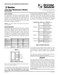
INSTALLATION AND MAINTENANCE INSTRUCTIONS<strong>CZ</strong>-6<strong>Six</strong> <strong>Zone</strong> <strong>Interface</strong> <strong>Module</strong>3825 Ohio Avenue, St. Charles, Illinois 60174800/736-7672, FAX: 630/377-6495www.systemsensor.comSPECIFICATIONSNormal Operating Voltage:Stand-By Current:Alarm Current:Temperature Range:Humidity:Dimensions:Accessories:Wire Gauge:Maximum IDC Wiring Resistance:External Supply VoltageDC Voltage:Ripple Voltage:Current:IDC:15-32 VDC2 mA40 mA (assumes all six LEDs solid on)32°F to 120°F (0°C to 49°C)10 to 85% Noncondensing6.8″H x 5.8″W x 1.25″DCH-6 Chassis; BB-2 Cabinet; BB-6 Cabinet12-18 AWG25 Ohms18-28 volts power limited0.1 volts RMS maximum90mA per moduleSupervised and power limitedBEFORE INSTALLINGThis information is included as a quick reference installationguide. Refer to the appropriate control panel installation manualfor detailed system information. If the modules will be installedin an existing operational system, inform the operator and localauthority that the system will be temporarily out of service.Disconnect the power to the control panel before installing themodules. This system contains static sensitive components.Always ground yourself with a proper wrist strap before handlingany circuits so that static charges are removed from the body. Themodule housing should also be grounded.NOTICE: This manual should be left with the owner/userof this equipment.GENERAL DESCRIPTIONThe <strong>CZ</strong>-6 <strong>Six</strong> <strong>Zone</strong> <strong>Interface</strong> <strong>Module</strong> is intended for use in anintelligent alarm system. Each module provides an interfacebetween the intelligent alarm system and a conventional alarmsystem loop. A common SLC input is used for all modules, andthe initiating device loops share a common supervisory supplyand ground. Otherwise, each monitor operates independentlyfrom the others. Each module has its own unique address.A pair of rotary code switches is used to set the address of thefirst module from 01 to 94. The remaining modules are automaticallyassigned to the next five higher addresses. Provisions areincluded for disabling a maximum of two unused modules torelease the addresses to be used elsewhere. Each module also haspanel controlled bicolor LED indicators. The panel can cause theLEDs to blink, latch on, or latch off.Compatible Two-wire <strong>System</strong> <strong>Sensor</strong> Smoke Detectors for use with <strong>CZ</strong>-6DET.DETECTORMODEL DET. ID MANUFACTURER BASE MODEL MAX DET.1151 A SYSTEM SENSOR B110LP, B401 201451 A SYSTEM SENSOR B401, B401B 201451DH A SYSTEM SENSOR DH400 202151 A SYSTEM SENSOR B110LP, B401 202451 A SYSTEM SENSOR DH400, B401B, B401 202451TH A SYSTEM SENSOR B401, B401B 205451 A SYSTEM SENSOR B401 201100 A SYSTEM SENSOR N/A 201400 A SYSTEM SENSOR N/A 20** 2100AT A SYSTEM SENSOR N/A 202100B A SYSTEM SENSOR N/A 202100D A SYSTEM SENSOR N/A 202100S A SYSTEM SENSOR N/A 202100TB A SYSTEM SENSOR N/A 202100TD A SYSTEM SENSOR N/A 202100TS A SYSTEM SENSOR N/A 202300B A SYSTEM SENSOR N/A 202300TB A SYSTEM SENSOR N/A 202400 A SYSTEM SENSOR N/A 202400TH A SYSTEM SENSOR N/A 20* 2W-B A SYSTEM SENSOR N/A 20* 2W-TB A SYSTEM SENSOR N/A 20DH100LP A SYSTEM SENSOR N/A 20* Class B, Style B only** No Accessory will be supported by 2100ATD500-49-00 1 I56-1799-04
67 85BASE ADDRESS01315 14ADDRESSDISABLENONEONETWOTHREE67 85BASE ADDRESS01315 144 56 7 8 932ADDRESSDISABLENONEONETWOTHREE4 56 7 8 932Included:(5) 1 x 4 Terminal Blocks (2) 1 1 / 4 ” Stand offs (3) Shunts(4) Machine Screws (2) Nuts (1) Long Power Supply Jumper(6) 3.9k OhmEnd of Line ResistorsShipped on Board:(2) Shunts in Class A/B position(Shipped in Class B position, remove shunts for Class A)C0202-00COMPATIBILITY REQUIREMENTSTo ensure proper operation, this module shall be connected to acompatible system control panel. Contact <strong>System</strong> <strong>Sensor</strong> for a listof compatible detectors.CabinetsA BB-6 cabinet will house the CH-6 chassis with up to six <strong>CZ</strong>-6modules installed on it. Refer to cabinet installation documentsfor dimensions.The BB-2 cabinet houses one or two <strong>CZ</strong>-6 modules on the internalchassis that is part of the cabinet. Refer to cabinet installationdocuments for dimensions.INSTALLATION STEPS1. Cabinet MountingIn a clean, dry area, mount the backbox using the four holes providedin the back surface of the cabinet (Figure 3).2. Chassis InstallationThe CH-6 chassis is mounted in the BB-6 cabinet. It is shippedwith two self-threading screws, which are used to fasten the chassisto the back wall of the cabinet. (Figure 4).BackboxMountingHolesCOMPONENTSFollowing are descriptions of the <strong>CZ</strong>-6 mounting frameworks.There are two mounting options for <strong>CZ</strong>-6 modules:• Up to six <strong>CZ</strong>-6 modules can be installed on a CH-6 in a BB-6cabinet• One or two <strong>CZ</strong>-6 modules can be installed in a BB-2 cabinetChassisThe CH-6 chassis is used to mount <strong>CZ</strong>-6 modules in a BB-6, cabinet.It accommodates up to six <strong>CZ</strong>-6 modules in a single cabinetrow three modules wide and two modules deep.Figure 3: Typical mounting hole locationsC0235-00Mount with self-threading screwsto back of cabinetC0236-00Figure 1: CH-6 ChassisC0206-00The BB-2 cabinet has a built-in chassis that will accommodateone or two <strong>CZ</strong>-6 modules.Figure 4: Mounting the CH-6 chassisThe BB-2 cabinet comes with the chassis already installed, so nomounting is necessary.3. <strong>Module</strong> InstallationThere are two methods for installing a module in the rear positionof a chassis. Method one is for installation of a rear module only,when no module will be installed in front of it. Refer to Figure 5for instructions. Method two is for installation of a rear modulewhen another module will be installed in the chassis position infront of it. Refer to Figures 6a and 6b for method two. All necessaryscrews and standoffs are supplied with the modules.43211 09 10111243211 09 101112231Figure 2: BB-2 CabinetC0234-00 C0237-00The front <strong>CZ</strong>-6 module positions of each chassis are offset belowthe rear <strong>CZ</strong>-6 module positions so that all of the status indicatorsare visible.Figure 5: Installation of rear module only, method oneD500-49-00 2 I56-1799-04
Step 1: Insert the bottom of the <strong>CZ</strong>-6 module down into arear slot on the chassis.Step 2: Carefully swing the upper edge of the board backtowards the back of the chassis until it touches the twostandoffs.Step 3: Align two 4-40 screws with the two standoffs and tighten.Step 4: Address and wire the modules according to the instructionsin this manual.The steps in Figures 6a and 6b describe and illustrate moduleinstallation when the rear chassis position and the position infront of it will be filled. Front position installation is possible onlyif the rear position is filled with another module.Figure 6a:Installation of <strong>CZ</strong>-6 module in a rearchassis position, method twoStep 1: Insert the bottom edge of the <strong>CZ</strong>-6 module down into arear slot of the chassis.Step 2: Carefully swing the upper edge of the board towards theback of the chassis until it touches the short standoffattached to the chassis.Step 3: Align the long standoff with the short standoff andtighten.121Figure 6b:Installation of <strong>CZ</strong>-6 module in front chassis positionStep 1: Insert the bottom edge of the <strong>CZ</strong>-6 module downinto a front slot of the chassis.Step 2: Carefully swing the upper edge of the boardtowards the back of the chassis until it touches the 1 1 / 4″(31.75mm) standoffs installed on the rear module.3C0225-00C0226-00Step 3: Align two 4-40 screws with the two standoffs andtighten.Step 4: Address and wire the modules according to theinstructions in this manual.WIRINGNOTE:All wiring must conform to applicable local codes,ordinances, and regulations.1. Install module wiring in accordance with the job drawings andappropriate wiring diagrams.2. All wiring to the <strong>CZ</strong>-6 is done via terminal blocks. In order toproperly make electrical connections strip approximately 1 / 4 ″of insulation from the end of wire, sliding the bare end of thewire under the clamping plate screw.3. Set the address on the modules per the job drawing. Use therotary code switches to set the address of the first module(between 01 and 94).In Class B operation, the remaining modules are automaticallyassigned to the next five higher addresses. For example,if the base address switch is set to 28, the next fivemodules will be addressed to 29, 30, 31, 32 and 33.The module is shipped in Class B position, remove shunts forClass A. When operating in Class A, alternate modules are pairedtogether (+0/+1, +2/+3, +4/+5), resulting in a total of threemodules. For example, if the base address switch is set to 28, then30 and 32 will be automatically assigned to the modules while29, 31 and 33 are available to be used for other modules on theSLC. For Class A and B operation, DO NOT set the lowest addressabove 94, as the other modules will be assigned to nonexistentaddresses.4. A shunt is provided to disable a maximum of two unused modulesin Class B operation and Class A operation. <strong>Module</strong>s aredisabled from the highest address and work downward. If twomodules are disabled, the lowest four addresses will be functional,while the highest two will be disabled. For example, inClass B operation, if the shunt for Address Disable is placedon “two” and the base switch is set to 28, the modules will beassigned to 28, 29, 30 and 31 while disabling the highest twopositions.NOTE:NOTE:Place unused shunts on single pin to store on board forfuture use.Power must not be applied to the unit when changingfunctionality of the shunts.WIRING NOTES• Power-limited circuits must employ type FPL, FPLR, or FPLPcable as required by Article 760 of the NEC.• All wiring must be in accordance with the NEC, NFPA 72 andall other applicable codes and standards. All external powersupplies must be power limited with battery back-up. Allexternal power supplies and detectors must be UL listed for fireprotection signaling applications.FCC StatementThis device complies with part 15 of the FCC Rules. Operation is subject to the following two conditions: (1) This device may not cause harmful interference, and (2) thisdevice must accept any interference received, including interference that may cause undesired operation.Note: This equipment has been tested and found to comply with the limits for a Class B digital device, pursuant to Part 15 of the FCC Rules. These limits are designed toprovide reasonable protection against harmful interference in a residential installation. This equipment generates, uses and can radiate radio frequency energy and,if not installed and used in accordance with the instructions, may cause harmful interference to radio communications. However, there is no guarantee that interferencewill not occur in a particular installation. If this equipment does cause harmful interference to radio or television reception, which can be determined by turningthe equipment off and on, the user is encouraged to try to correct the interference by one or more of the following measures:– Reorient or relocate the receiving antenna.– Increase the separation between the equipment and receiver.– Connect the equipment into an outlet on a circuit different from that to which the receiver is connected.– Consult the dealer or an experienced radio/TV technician for help.D500-49-00 3 I56-1799-04
3.9K EOLRESISTOR(INCLUDED)A2143-10FROM PANEL ORPREVIOUS DEVICETO NEXT DEVICE+–+–CONNECT MODULES TOLISTED COMPATIBLECONTROL PANELS ONLY+–+–CLASS B IDC (TYPICAL)POWER TO THE NEXT INTERFACEMODULE MUST BE EXTERNALLYSWITCHED TO RESET THE DETECTORS.(+)(–)POWER-LIMITEDAND SUPERVISED— + — +— + — +— + — + — + — + — + — +IN OUT +0 +1 +2 +3 +4 +5SLCEXTERNAL SUPPLYIDC ADDRESS IDC ADDRESS IDC ADDRESST6 T5A/B SELECTA/B SELECTDISABLE 1DISABLE 24 5 6 7 8 9321 0BASE ADDRESS4 5 6 7 8 9321 0STATUSINDICATORSCOMMUNICATION LINE 32 VDC MAX.TWISTED PAIR IS RECOMMENDED.Figure 7: <strong>Interface</strong> two-wire conventional detectors – Class B, Style B.1. To use a common power supply between multiple <strong>CZ</strong>-6 modules,connect a long power supply jumper from T5 or T6 to T5or T6 on the adjacent <strong>CZ</strong>-6 module.DETECTORS MUST BE UL LISTED COMPATIBLE WITH THE MODULE.INSTALL DETECTORS PER MANUFACTURER'S INSTALLATION INSTRUCTIONS.Figure 7C0240-00CONNECT MODULES TO LISTED COMPATIBLECONTROL PANELS ONLYFROM PANEL ORPREVIOUS DEVICETO NEXT DEVICE–+CLASS A IDC (TYPICAL)POWER TO THE NEXT INTERFACEMODULE MUST BE EXTERNALLYSWITCHED TO RESET THE DETECTORS.+–+––+(+)(–)IDC 2IDC 3POWER-LIMITEDAND SUPERVISED— + — +— + — + — + — + — + — +IN OUT +0 +1 +2 +3 +4 +5EXTERNAL SUPPLYIDC ADDRESS IDC ADDRESS IDC ADDRESS— + — +SLCT6 T5A/B SELECTA/B SELECTDISABLE 1DISABLE 24 5 6 7 8 9321 0BASE ADDRESS4 5 6 7 8 9321 0STATUSINDICATORSCOMMUNICATION LINE 32 VDC MAX.TWISTED PAIR IS RECOMMENDED.DETECTORS MUST BE UL LISTED COMPATIBLE WITH THE MODULE.INSTALL DETECTORS PER MANUFACTURER'S INSTALLATION INSTRUCTIONS.Figure 8Figure 8: <strong>Interface</strong> two-wire conventional detectors – Class A, Style D.C0241-001. To select Class A, remove the two shunts from the “A/B select”positions.2. To use a common power supply between multiple <strong>CZ</strong>-6 modules,connect a long power supply jumper from T5 or T6 to T5or T6 on the adjacent <strong>CZ</strong>-6 module.D500-49-00 4 I56-1799-04