Installation Instructions - System Sensor Canada
Installation Instructions - System Sensor Canada
Installation Instructions - System Sensor Canada

Create successful ePaper yourself
Turn your PDF publications into a flip-book with our unique Google optimized e-Paper software.
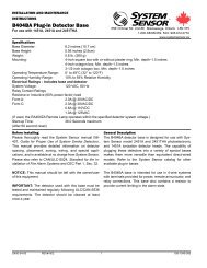
INSTALLATION AND MAINTENANCE INSTRUCTIONSB401BA Plug-in Detector BaseFor use with the following smoke detectors:1451A, and 2451A.6581 Kitimat Rd., Unit #6, Mississauga, Ontario, L5N 3T51-800-SENSOR2, FAX: 905-812-0771WWW.SYSTEMSENSOR.CASpecificationsBase Diameter:6.2 inches (15.7 cm)Base Height:1.1 inches (2.8 cm)Weight: 0.3 lb. (130 g)Mounting:4-inch square box with or without plaster ring. Min. Depth–1.5 inches4-inch octagon box. Min. Depth–1.5 inches3-1/2 inch octagon box. Min. Depth–1.5 inchesOperating Temperature Range: 0° to +49°C (32° to 120°F)Operating Humidity Range: 10% to 93% Relative Humidity, noncondensingElectrical Ratings — includes base and detector<strong>System</strong> Voltage:12/24 VDCMaximum Ripple Voltage: 4 Volts peak to peakStart-up Capacitance:0.02 µF MaximumStandby Ratings:8.5 VDC Minimum; 35 VDC Maximum120 µA MaximumAlarm Ratings:4.2 VDC Minimum at 10 mA; 6.6 VDC Maximum at 100 mA(Alarm current must be limited to 100 mA by the control panel. If used, the RA400remote lamp operates within specified detector alarm currents.)Reset Voltage:2.5 VDC MinimumReset Time:0.3 Seconds MaximumStart-up Time:34.0 Seconds MaximumBefore InstallingPlease thoroughly read the <strong>System</strong> <strong>Sensor</strong> manual I56-407, Guide for Proper Use of <strong>System</strong> Smoke Detectors,which provides detailed information on detector spacing,placement, zoning, wiring, and special applications. Copiesof this manual are available at no charge from <strong>System</strong><strong>Sensor</strong>. Please also refer to CAN4-S524, Standard for the<strong>Installation</strong> of Fire Alarm <strong>System</strong>s, and CEC Part 1, Sec.32..NOTICE: This manual should be left with the owner/userof this equipment.General DescriptionThe B401BA plug-in detector base is used with <strong>System</strong><strong>Sensor</strong> model 2451A photoelectronic detector heads andmodel 1451A ionization detector heads. The capability ofplugging these detectors into a variety of special basesmakes them more versatile than equivalent direct-wiredmodels. Refer to the <strong>System</strong> <strong>Sensor</strong> catalog for otheravailable plug-in detector bases.This base is intended for use in 2-wire systems, withscrew terminals provided for power, ground, and remoteannunciator connections.IMPORTANT: The detector used with this base must betested and maintained regularly following CAN/ULC-S536requirements. The detector used with this base should becleaned at least once a year.D450-01-01 I56-1035-000
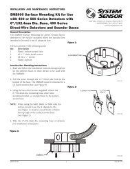
MountingThis detector base mounts directly to 3-1/2-inch and4-inch octagon boxes, and 4-inch square boxes (with orwithout plaster rings). To mount, remove the decorativering by turning it in either direction to unhook the snaps,then separate the ring from the base.Install the base to the box using the screws supplied withthe junction box and the appropriate mounting slots in thebase (see Figure 1). Place decorative ring onto base, thenturn in either direction until the ring snaps in place.Figure 1. Mounting base to box:SHORTINGSPRINGSNAP ONDECORATIVERINGSCREWS (NOTSUPPLIED)<strong>Installation</strong> GuidelinesAll wiring must be installed in compliance with the NationalElectrical Code and the local codes having jurisdiction.Proper wire gauges should be used. Theconductors used to connect smoke detectors to controlpanels and accessory devices should be color-coded toreduce the likelihood of wiring errors. Improper connectionscan prevent a system from responding properly inthe event of a fire.DETECTORBASEBOX (NOTSUPPLIED)For signal wiring (the wiring between interconnecteddetectors), it is recommended that the wire be no smallerthan 18 gauge (1.0 square mm). Wire sizes up to 12gauge wire (2.5 square mm) may be used with the base.For best system performance, the power (+) and (–) loopwires should be twisted pair and installed in separategrounded conduit to protect the loop from extraneouselectrical interference.Smoke detectors and alarm system control panels havespecifications for allowable loop resistance. Consult theA78-1175-01control panel manufacturer’s specifications for the totalloop resistance allowed for the particular model controlpanel being used before wiring the detector loops.Locate installations where the normal ambient temperaturesdo not exceed 100° F.Figure 2. Typical wiring diagram for 2-wire detector systems:2-WIRE CONTROL PANELREMOTEANNUNCIATOR1243REMOTEANNUNCIATOR1243EOLCLASS A OPTIONAL WIRINGA78-1175-04D450-01-01 I56-1035-000
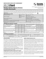
Wiring <strong>Instructions</strong>CAUTIONFor system supervision — For terminals 2, 3, and 4 donot use looped wire under terminals. Break wire run toprovide system supervision of connections.Wire connections are made by simply stripping insulationfrom the end of the wire, sliding the bare end of the wireunder the clamping plate, and tightening the clampingplate screw. Use the strip gauge molded into the base forease of wiring to terminals 1 through 4.The zone wiring of the detector base should be checkedbefore the detector heads are installed in them. To makethis possible, this base contains a special spring-typeshorting jumper. After a detector base is properly wiredand mounted on an electrical box, make sure that thejumper spring is in contact with the base of Terminal 3.This temporary connection shorts the negative-in andnegative-out leads and permits the wiring of the loop to bechecked for continuity.To make the detector tamper-resistant, use needle-nosepliers to break the smaller tab at the scribed line on thetamper- resistance tab. Figure 3A shows the location ofthis tab on the detector mounting bracket. To remove adetector from the bracket after it has been made tamperresistant, use a small screwdriver or other similartool, to depress the tamper-resistance tab in the slot onthe mounting bracket, and rotate the detector counterclockwise(see Figure 3B).NOTE: The decorative ring must be removed before thesmoke detector can be detached from the baseafter the tamper-resistant capability is enabled.The tamper-resistance feature can be defeated by breakingand removing the plastic lever from the base. However,this prevents ever using the feature again.Once all the detector bases have been wired and mounted,and the loop wiring has been checked, the detectorheads may be installed in the bases. The shorting springin the base will disengage automatically when the detectorhead is removed from the base. DO NOT remove theshorting spring since it reengages as the detector head isturned into the base, completing the circuit.Tamper-resistance FeatureCAUTIONDo not use the tamper-resistance feature if the XR2 removaltool is to be used.The tamper-resistant tab, in the detector mountingbracket, can make the detector tamper-resistant by makingit necessary to use a small screwdriver or similar toolto detach the detector from the bracket.Figure 3A. Activating the tamper-resistance feature:Figure 3B. Removing detector head from the base:PLASTIC LEVERBREAK TAB ATDOTTED LINE BYTWISTING TOWARDCENTER OF BASE.USE SMALL-BLADEDSCREWDRIVER TOPUSH PLASTIC LEVERIN DIRECTION OFARROW.A78-1175-03D450-01-01 3 I56-1035-000
Please refer to insert for the Limitations of Fire Alarm <strong>System</strong>sThree-Year Limited Warranty<strong>System</strong> <strong>Sensor</strong> warrants its enclosed smoke detector to be free from defects in materialsand workmanship under normal use and service for a period of three yearsfrom date of manufacture. <strong>System</strong> <strong>Sensor</strong> makes no other express warranty for thissmoke detector. No agent, representative, dealer, or employee of the Company hasthe authority to increase or alter the obligations or limitations of this Warranty. TheCompany’s obligation of this Warranty shall be limited to the repair or replacementof any part of the smoke detector which is found to be defective in materials orworkmanship under normal use and service during the three year period commencingwith the date of manufacture. After phoning <strong>System</strong> <strong>Sensor</strong>’s toll free number1-800-SENSOR2 (736-7672) for a Return Authorization number, send defectiveunits postage prepaid to: <strong>System</strong> <strong>Sensor</strong>, Repair Department, RA #__________,6581 Kitimat Rd., Unit #6, Mississauga, Ontario, L5N 3T5. Please include a notedescribing the malfunction and suspected cause of failure. The Company shall notbe obligated to repair or replace units which are found to be defective because ofdamage, unreasonable use, modifications, or alterations occurring after the dateof manufacture. In no case shall the Company be liable for any consequential orincidental damages for breach of this or any other Warranty, expressed or impliedwhatsoever, even if the loss or damage is caused by the Company’s negligence orfault. Some states do not allow the exclusion or limitation of incidental or consequentialdamages, so the above limitation or exclusion may not apply to you. ThisWarranty gives you specific legal rights, and you may also have other rights undercommon law.D450-01-01 REV#: 002 4 I56-1035-000© <strong>System</strong> <strong>Sensor</strong> 2000