Slant Back Lavatory Faucet Application Notes (PDF) - Central Brass
Slant Back Lavatory Faucet Application Notes (PDF) - Central Brass
Slant Back Lavatory Faucet Application Notes (PDF) - Central Brass

You also want an ePaper? Increase the reach of your titles
YUMPU automatically turns print PDFs into web optimized ePapers that Google loves.
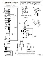
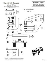
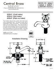
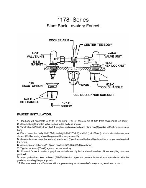
1178 Series<strong>Slant</strong> <strong>Back</strong> <strong>Lavatory</strong> <strong>Faucet</strong>FAUCET INSTALLATION:1. Tee body will assemble to 4" to 6" centers. (For 4" centers, cut off 1/4" from each end of tee body.)2. Assemble right and left valve bodies to tee body as shown.3. Turn locknuts (53-AZ) down the full length of each valve body and place one (1) gasket (491-U) on each valvebody.4. Place center tee body (U-2171-A) and right (U-2170-AR) and left (U-2170-AL) valve bodies in lavatory asshown. (Rubber o-ring should be greased for easy assembly.)5. Assemble spout to center tee body as shown. (Spout should be hand tightened for a proper seal againstthe o-ring.)6. Assemble escutcheons (510) and handles (523-C & 523-H) as shown.7. Tighten locknuts (53-AZ) against back of lavatory.8. Connect faucet to water supply lines as indicated by hot and cold handles. <strong>Brass</strong> coupling nuts areprovided.9. Insert pull rod and knob sub-unit (SU-754-KA) thru spout and assemble to rocker arm as shown with theguide for installing the pop-up drain.10. Remove aerator and flush faucet for approximately ten minutes before replacing aerator on spout.
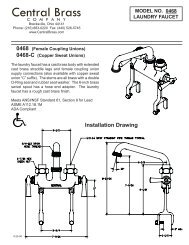
1178 Series<strong>Slant</strong> <strong>Back</strong><strong>Lavatory</strong> <strong>Faucet</strong>GUIDE FOR INSTALLING POP-UP DRAIN:1. Remove stopper and drain flange from pop-up tee and remove locknut, steel washer and rubber washer fromdrain flange.2. Apply a layer of soft (plumber set) to the underside of drain flange and insert downward thru lavatory.3. Assemble rubber washer, steel washer and locknut to drain flange as shown. Assemble pop-up tee to drainflange, tighten locknut from underside and assemble ball lever to tee as shown. (NOTE: Ball lever pointstowards the rear.)4. Assemble pull rod, clevis and clip as shown, tighten set screw and insert stopper.