autocad drawings of precast concrete cladding panels for - NEES
autocad drawings of precast concrete cladding panels for - NEES
autocad drawings of precast concrete cladding panels for - NEES

You also want an ePaper? Increase the reach of your titles
YUMPU automatically turns print PDFs into web optimized ePapers that Google loves.
AUTOCAD DRAWINGS OF PRECASTCONCRETE CLADDING PANELS FORHIGH SEISMICITY REGIONAuthor: Diana LinHome Institution: San Jose State UniversityREU Institution: University <strong>of</strong> Cali<strong>for</strong>nia, San DiegoPI: Tara C. HutchinsonMentor: Kurt McMullinOctober 10 th , 2011
Table <strong>of</strong> ContentsProject Overview .................................................................................................................................... 1Literature Review ................................................................................................................................... 2Contributions ........................................................................................................................................... 4AutoCAD .............................................................................................................................................. 4Construction Contributions................................................................................................................ 9Conclusion ............................................................................................................................................. 10Acknowledgements .............................................................................................................................. 11References ............................................................................................................................................ 12ii | P a g e
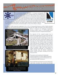
Project OverviewNatural disasters can happen at any time without warning. Damaged buildings andstructures can be dangerous <strong>for</strong> people. Dependent on how large the earthquake is,towns and cities can be destroyed in seconds. Engineers we must plan and design toensure that they create a structure that will not collapse because <strong>of</strong> an earthquake. Inaddition to building damage, earthquakes can cause severe damage to pipelines andcreate fire hazards. There has not been much research focusing on how fire hazardscan occur during and after an earthquake has taken place.The <strong>NEES</strong> site at UC San Diego will be testing a full scale five story rein<strong>for</strong>ced <strong>concrete</strong>commercial building and its nonstructural components on the large outdoor shake tableunder the Principal Investigator Tara Hutchinson. This test will focus on thenonstructural components <strong>of</strong> the building and review in depth how fire safety hazardschange during an earthquake and post earthquake. While the building is shaking theobjects inside shake as well and many <strong>of</strong> the nonstructural components are torn <strong>of</strong>f andthrown around the building. Gas pipes become damaged and leakage occurs, and withthe combination <strong>of</strong> hot light fixtures, fires can easily erupt and cause a chaotic inferno.Precast <strong>concrete</strong> <strong>panels</strong> provide a decorative coverage <strong>for</strong> the structure componentslike the slabs, beams and columns (McMullin et al, 2003). They are nonstructuralcomponents <strong>of</strong> a building because their self weight is supported on the frame structure.In the past, <strong>cladding</strong> <strong>panels</strong> have failed during an earthquake and have also causedmany deaths (Sielaff et al, 2005). For this <strong>NEES</strong> project, <strong>precast</strong> <strong>concrete</strong> <strong>cladding</strong><strong>panels</strong> were a recent addition and funding was not yet available <strong>for</strong> the system.<strong>NEES</strong> REU students from San Jose State University (SJSU) assisted the pr<strong>of</strong>essors todevelop a proposal <strong>for</strong> funding. A proposal was being written to provide in<strong>for</strong>mation tothe <strong>concrete</strong> <strong>cladding</strong> supplier. Various <strong>drawings</strong> were needed to help Pr<strong>of</strong>essors TaraHutchinson and Kurt McMullin to show the <strong>cladding</strong> supplier how the design will look onthe current structure. There<strong>for</strong>e, draft <strong>drawings</strong> were needed to show a visual layout <strong>of</strong>the panel placements and how <strong>panels</strong> were going to be connected to the frame.The five story rein<strong>for</strong>ced <strong>concrete</strong> structure was already in the beginning phases <strong>of</strong>construction when the SJSU team arrived on site. Figure 1 shows a 3 dimensionalmodel <strong>of</strong> the frame structure <strong>for</strong> the test specimen. The picture on the right is the samebuilding with <strong>concrete</strong> <strong>cladding</strong> <strong>panels</strong>. Panels will only be placed from the second floorto the ro<strong>of</strong>.1 | P a g e
Figure 1: (Left) The structural system <strong>of</strong> the building used to test the nonstructural components (Right) the same buildingwith addition <strong>of</strong> the <strong>cladding</strong> <strong>panels</strong> (Drawn by Steve Mintz)Literature ReviewEngineers design the main frame <strong>of</strong> the structure. During the design process, differentloads are considered <strong>for</strong> design, including nonstructural components. Although loadsare considered <strong>for</strong> design, the main focus is ensuring that the structure will not collapsedue to gravity or lateral loads. Nonstructural components in the past were not designed<strong>for</strong> moving <strong>for</strong>ces like earthquakes. Examples <strong>of</strong> nonstructural components are pipingsystems which are used to transport water to different levels <strong>of</strong> the building, heatingventilation and air conditioning (HVAC) systems which are used regulating temperaturesin different rooms, and lighting fixtures that provide light to the building.When an earthquake occurs, the frame <strong>of</strong> the building moves side to side and causesan inertial <strong>for</strong>ce to act on the components. This <strong>for</strong>ce is similar to when one is in amoving vehicle that one’s body feels the <strong>for</strong>ce when the car accelerates and brakes(FEMA, 2005). Damage can occur to the nonstructural components during anearthquake when poor connections are made to the main structure. Figure 2 shows thedamage from the non structural components after the Northridge earthquake <strong>of</strong> 1994.Studs separated and caused the ceiling to collapse to the floor (FEMA, 2011).Concrete <strong>cladding</strong> <strong>panels</strong> can cause damage and in the past century, they have alsocaused deaths during earthquakes. Figure 3 shows the <strong>cladding</strong> <strong>panels</strong> at the JCPenney’s store that fell <strong>of</strong>f the structure during the 1964 Alaska earthquake and causedtwo deaths (Arnold, 2009)..2 | P a g e
Figure 2: Damage to the nonstructural components due to incorrect metal stud partition (FEMA, 2011)Figure 3: J.C. Penney store in the 1964 Alaska earthquake caused <strong>concrete</strong> <strong>panels</strong> to fall (Arnold, 2009)New procedures were needed to help minimize damage and falling <strong>of</strong> <strong>concrete</strong> <strong>cladding</strong><strong>panels</strong>. In seismic regions, it is required that <strong>cladding</strong> <strong>panels</strong> have a Lateral Force-Resisting System (LFRS) and in addition, they have to have a flexible connection thatallows movements at the connection point (Maneetes & Memar, 2009). This has shownnot only improvements to the <strong>concrete</strong> <strong>cladding</strong> <strong>panels</strong> but it has brought benefits to theoverall structure. With flexible connections, <strong>panels</strong> have been able to resist wind andseismic <strong>for</strong>ces (Li, 2010). This provides better per<strong>for</strong>mance during an earthquake3 | P a g e
ContributionsCladding <strong>panels</strong> were a new addition to the study <strong>of</strong> this five story rein<strong>for</strong>ced <strong>concrete</strong>building to test the connections <strong>of</strong> the <strong>panels</strong> to the building. In addition, a fire test willbe completed after the earthquake test to examine how easily the fire will spread fromfloor to floor with the addition <strong>of</strong> the <strong>cladding</strong> <strong>panels</strong>.The <strong>NEES</strong> REU students on this project worked closely with Pr<strong>of</strong>essors TaraHutchinson and Kurt McMullin to develop a proposal <strong>for</strong> funding <strong>for</strong> the <strong>cladding</strong>systems. Two REU students were from UC San Diego who focused on the analysis <strong>of</strong>the <strong>cladding</strong> <strong>panels</strong> and ordering <strong>cladding</strong> supplies. The other two students were fromSan Jose State University and helped prepared detailed <strong>drawings</strong> <strong>of</strong> the <strong>cladding</strong><strong>panels</strong> and their connections <strong>for</strong> the supplier. Pr<strong>of</strong>essor Kurt McMullin emailed handsketched <strong>drawings</strong> and called via phone to discuss how everything should look. Theteam provided him AutoCAD <strong>drawings</strong> based on his descriptions. Over the summer, theteam was able to produce approximately 80 different <strong>drawings</strong>.AutoCADEach week on Tuesday and Friday, the REU team from San Jose State had deadlinesto provide new and most updated AutoCAD <strong>drawings</strong> <strong>for</strong> Tara Hutchinson and KurtMcMullin. The importance <strong>of</strong> this was to ensure that when they had their meetings withthe Precast Concrete Institute (PCI), they had <strong>drawings</strong> to support their proposal.Although 80 <strong>drawings</strong> were completed, this paper focuses on six: an elevation view, afloor plan, an angle embedment plate, and three detail <strong>drawings</strong> <strong>of</strong> the installation <strong>of</strong> theembedment plates, a <strong>concrete</strong> panel, and the connect to the beam with the panel.Four different elevation views were needed <strong>for</strong> the building to show where and whattype <strong>of</strong> <strong>cladding</strong> <strong>panels</strong> will be needed. Figure 4 shows the south view <strong>of</strong> the buildingand all the <strong>panels</strong> that will be used. Each panel is labeled to indicate the different types<strong>of</strong> <strong>panels</strong> that are needed. Spandrel Panel 1 (SP-1) will be used <strong>for</strong> the covering upmost <strong>of</strong> the slab edges. Spandrel Panel Returns (SR-1) will also be used to cover theslabs near the corners in addition to columns A and C. They are U-shaped <strong>panels</strong> andare mainly on the west and east views. Column Cover Long (CL-1) is placed to hidecolumn B while Column Cover Short (CS-1) is placed to hide half <strong>of</strong> the columns A andC. Column Cover Returns (CR-1) are L-shape <strong>panels</strong> that are wrapped around thecolumns A and C. When <strong>panels</strong> meet in between columns, a 2-inch seismic gap isneeded.4 | P a g e
Figure 4: Elevation <strong>of</strong> the south view <strong>of</strong> the <strong>NEES</strong> building <strong>for</strong> nonstructural componentsMore detailed <strong>drawings</strong> <strong>of</strong> the <strong>panels</strong> were needed to show how to attach them to themain structure. Figure 5 shows the interpretation <strong>of</strong> how the system will be installed;embedment plates (embeds) are located along the slab <strong>of</strong> the structure. This <strong>drawings</strong>hows the locations where the embedment plates will be installed from the centerline <strong>of</strong>each column. Steel embedment plates where used to provide a location to connect the<strong>cladding</strong> <strong>panels</strong> to the building. Figure 6 is a detailed drawing <strong>for</strong> the embedment plate5 | P a g e
Figure 5: A preliminary drawing <strong>of</strong> how the <strong>concrete</strong> <strong>cladding</strong> <strong>panels</strong> were to attach to the slab <strong>of</strong> the buildingFigure 6: Drawing <strong>of</strong> the angle embedment place on the slabs and beams to connect the <strong>cladding</strong> <strong>panels</strong> to the structure6 | P a g e
A detailed view <strong>of</strong> the installation <strong>of</strong> the angled embedment plates on the slabs isprovided on Figure 7. To secure the location <strong>of</strong> the plate when it is being cast into the<strong>concrete</strong> slab, 180 degree hooks are looped around the stud. When the plates aresecured in place in the slab, connections can be made to attach the spandrel <strong>panels</strong> tothe structure.Figure 7: The installation <strong>of</strong> the angle embedment plates on the slabFigure 8 shows the different connections that will be placed on a spandrel panel. Thethree main connections will be the lateral seismic connection in the middle <strong>of</strong> the paneland two bearing connections on each side. Push-pull connections are also placed in thispanel because this will allow vertical correction due to the rod passing a large hole.7 | P a g e
Figure 8: Detail drawing <strong>of</strong> different connections placed on the spandrel <strong>panels</strong>The beam designs varied depending on the floor they were located on. Most beams hadthe top aligned and flush with the slab, but a new beam was being tested which was apartial upturn beam that was to be located on the second floor. In-depth <strong>drawings</strong> wereneeded to show how the two would differ because embedment plates were also placedon the beams to carry the <strong>cladding</strong> <strong>panels</strong>. Figure 9 shows the two different cases in thesection view. Since the beam is partial upturn, placement <strong>of</strong> the plates will be different.Drawings <strong>for</strong> the installation <strong>of</strong> the embedment plates <strong>for</strong> the upturn beam are still to bedetermined.8 | P a g e
Figure 9: Detail drawing <strong>of</strong> different layouts <strong>for</strong> each floor with different beamsThrough this AutoCAD experience I was able to understand working with numerousdeadlines in one week. Since deadlines were so critical <strong>for</strong> this project, there were manytimes that I had to bring the work home with me. I had to learn how to reach out toothers when I did not understand the concepts completely. First I would attempt thedrawing myself and when I got stuck, I asked my peers. We would work on it togetheruntil we both did not understand and our last option was to call our pr<strong>of</strong>essor.Communication was difficult since he was out <strong>of</strong> the country. Through all the stress anddifficulties, I leave with in depth knowledge <strong>of</strong> the program.Construction ContributionsThe <strong>NEES</strong> REU students were out on site daily to provide assistance to the construction<strong>of</strong> the building. Different minor tasks were needed to provide ease to both theconstruction workers and the PhD students. Some <strong>of</strong> the tasks were to inspect the steelbe<strong>for</strong>e the day <strong>of</strong> <strong>concrete</strong> pouring, install strain gages on steel members, per<strong>for</strong>mslump tests <strong>for</strong> the <strong>concrete</strong> and prepare cylinders <strong>for</strong> <strong>concrete</strong> strength testing.Concrete pours <strong>for</strong> the structure were approximately twice a week. REU students werenotified a day in advance to prepare the area to create test cylinders <strong>of</strong> the <strong>concrete</strong>.For every <strong>concrete</strong> truck, 15 cylinders needed to be made. Typically there were twotrucks requiring a total <strong>of</strong> 30 test cylinders. Be<strong>for</strong>e cylinders and pouring could begin, a9 | P a g e
decided to take an alternative route and discard all the <strong>drawings</strong> that were made thissummer and have their drafters created new <strong>drawings</strong>. The frame is almost complete.When they have finished the nonstructural components can be placed on the structure.If all goes as planned, the structure is schedule to test Spring 2012. I hope to return towatch the testing <strong>of</strong> this great project I worked on this summer.AcknowledgementsThis is a project that was funded by the National Science Foundation CMMI-0936505. Iwould like to thank the <strong>NEES</strong> REU program (EEC 1005054) <strong>for</strong> providing this wonderfulprogram to undergraduate students. Thanks to the project PI Dr. Tara C. Hutchinson,San Jose State University Pr<strong>of</strong>essor Kurt McMullin, the graduate and PhD students:Michelle Chen, Elide Pantoli, Steve Mintz, Elias Espino, Consuelo Aranda and DarjaHolz, the team at Englekirk and my fellow REU team on site: Cecilia Luu, Yujia Liu andYoshua Neuman. Thank you <strong>for</strong> the wonderful summer experience.11 | P a g e
ReferencesArnold, Chris 2009. Seismic Safety <strong>of</strong> the Building Envelope, National Institute <strong>of</strong>building Sciences Retrieved 8 Sept. 2011. Fromwww.wbdg.org/resources/env_seismicsafety.php?r=envelopeFEMA 2005 Earthquake Hazard <strong>for</strong> Mitigation <strong>for</strong> Nonstructural Elements (FEMA 74).United States: FEMA,FEMA 2011 Reducing Risk <strong>of</strong> Nonstructural Earthquake Damage (FEMA E-74) FourthEdition. United States: FEMALi, Jun Jie 2010. Earthquake Engineering Simulation With Flexible Cladding System.Thesis. University <strong>of</strong> Massachusetts,Maneetes, H., and Memar, A.M. 2009. Finite Element Modeling <strong>of</strong> Rein<strong>for</strong>ced ConcreteCladding Panel. Electronic Journal <strong>of</strong> Structural Eng. V9McMullin, K., Chan, K., Choi, C., and Kwong, A. 2003 Per<strong>for</strong>mance Engineering <strong>of</strong>Precast Cladding SystemsSielaff, B.J., Nielsen, R.J., and Schmeckpeper, E.R. 2005. Evolution <strong>of</strong> Design CodeRequirements <strong>for</strong> Exterior Elements and Connections. Earthquake EngineeringResearch Institute. Earthquake Spectra. Volume 2112 | P a g e