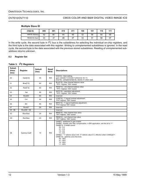
OMNIVISION TECHNOLOGIES, Inc.<strong>OV7610</strong>/OV7110CMOS COLOR AND B&W DIGITAL VIDEO IMAGE ICSIn the write cycle, the second byte in I 2 C bus is the subaddress for selecting the individual on-chip registers, andthe third byte is the data associated with this register. Writing <strong>to</strong> unimplemented subaddress is ignored. In the readcycle, the second byte is the data associated with the previous s<strong>to</strong>red subaddress. Reading of unimplemented subaddressreturns unknown.6.2 Register SetMultiple Slave IDCS[2:0] 000 001 010 011 100 101 110 111WRITE ID(hex) 42 46 4A 4E 52 56 5A 5EREAD ID (hex) 43 47 4B 4F 53 57 5B 5FTable 3.I 2 C RegistersSubaddress(hex)RegisterDefault(hex)Read/WriteDescriptions00 Gain[5:0] 00 RW01 Blue[7:0] 80 RW02 Red[7:0] 80 RW03 Sat 80 RW04 Rsvd04 80 RW reserved05 Cnt 00 RW06 Brt 80 RW07 Rsvd07 D4 RW reserved08 - 0B Rsvd08 ~ 0B - - reserved0C Blue Bias 20 RW0D Red Bias 20 RW0E Gamma Coeff 14 RWGC[5:0] – Gain setting.gain =(GC[5]+1)*(GC[4]+1)(GC[3:0] /16 +1)GC[7:6] - unimplemented bit, returns ‘X’ when read.BLU[7:0] – blue channel balance value.“FFh”- highest, “00h”-lowestRED[7:0] – red channel balance value.“FFh”- highest, “00h”-lowestSAT[7:0] – saturation adjustment.“FFh”- highest, “00h”-lowestCTR[7:0] – Y signal contrast adjustment.“FFh”-highest, “00h”-lowestBRT[7:0] – Y signal brightness adjustment.“FFh”-highest,“00h”-lowestBBS[5:0] – blue channel bias value.“3Fh”-highest, “00h”-lowestRBS[5:0] – red channel bias value.“3Fh”-highest, “00h”-lowestGAM[7] - additional 2x gain enableGAM[6] - disable color filter compensation, in BW application, set this bit <strong>to</strong> “1”GAM[4:3] - S-AWB control00 - 0.201 - 0.410 - 0.611 - 0.8GAM[2] – “1” selects value 0.45, “0” selects value 0.5, effective when COMC[2]=1GAM[1:0] – gamma curve fine tune.00 - 95%01 - 90%10 - 85%11 - 80%12 Version 1.3 15 May 1999
OMNIVISION TECHNOLOGIES, Inc.<strong>OV7610</strong>/OV7110 CMOS COLOR AND B&W DIGITAL VIDEO IMAGE ICSSubaddress(hex)RegisterDefault(hex)Read/WriteDescriptions0F WB Range A5 RW10 Exp 7F(I)/FF(P) RW11 Clock 00 RW12 Common A 24 RW13 Common B 01 RW14 Common C 04 RWRWB[7} - AEC method 1RWB[6] - AEC method 2RWB[5:4] - ALC black level00 - 1.20v01 - 1.26v10 - 1.30v11 - 1.40vRWB[3:2] - S-AWB upper level limit00 - 70%01 - 80%10 - 90%11 - 100%RWB[0:1] - S-AWB lower level limit00 - 10%01 - 20%10 - 30%11 - 40%EC[7:0] – Manual exposure setting.Valid range: interlace 00h~7Fh; progressive 00-FFhformula for exposure time:T EXPOSURE = T LINE x EC[7:0]x2; where T LINE = Frame Time/525.The actual time of a scan line is determined by the clock rate divider.This register is only effective when operated in manual adjust mode (COMB[0] = 0). Nevertheless,this register is always accessible through the I 2 C bus. It generally takes no morethan two fields for the image <strong>to</strong> reach the intended exposure after changing the setting.** This register must <strong>be</strong> initialized <strong>to</strong> the default value when switching <strong>be</strong>tween scanmodes, initialization must <strong>be</strong> done in manual exposure setting.SYN[7:6] - polarity for sync timing outputs00: HSYNC, CHSYNC, VSYNC = “- - + “01: HSYNC, CHSYNC, VSYNC = “- - - “10: HSYNC, CHSYNC, VSYNC = “+ - + “11: HSYNC, CHSYNC, VSYNC = “- + + “CLK[5:0] - system clock prescaler; formula for pixel clock rate:clock rate = CLK_input / ((CLK[5:0] + 1) * 2)The effect of the change is immediate. However, it generally takes about two fields for the image<strong>to</strong> reach the stable state.COMA[7] - “1” initiates the chip soft reset, the reset takes place after the acknowledge bit isissued, the effect is the same as powerup the chip, the chip is initialized <strong>to</strong> a defaultstate, all registers including I 2 C’s contents are set <strong>to</strong> default, this bit is self clearedafter the reset.COMA[6] - “1” selects mirror image.COMA[5] - “1” enables AGC, for it <strong>to</strong> take effect, COMB0 must <strong>be</strong> set.COMA[4] - “1” swaps Y/UV data in 8 Bit operation, data order YUYV...COMA[3] - “1” selects RGB image plane, “0” selects YCrCb image planeCOMA[2] - “1” enables au<strong>to</strong> channel balance, for it <strong>to</strong> take effect, COMB[0] must <strong>be</strong> set.COMA[1] - “1” Color Bar Test pattern.COMA[0] - “1” select Line BLC, “0” enables field BLC.COMB[7:6] - reserved.COMB[5] - “1” enable 8 bit operation, Y bus is active, UV bus is tri-stated.COMB[4] - “1” enables CCIR656 bus operation, Y bus is active, UV bus is tri-stated.COMB[3] - selects a timing signal <strong>to</strong> pin CHSYNC;“1” is composite sync, “0” is horizontal sync.COMB[2] - “1” puts Y and UV buses in tri-state.COMB[1] - “1” initiates the single frame transfer, for this function <strong>to</strong> work, field drop mode(FD in REG 16) must set <strong>to</strong> “OFF”. See Figure 12., Single Frame Transfer Example,after this bit is set, HREF is only asserted for consecutive two fields <strong>be</strong>ginning atOdd field. This bit is cleared au<strong>to</strong>matically at the end of this frame. Clearing this bit inthe middle of active frame has no effect <strong>to</strong> the assertion of the current HREF.COMB[0] - main au<strong>to</strong> adjust mode enable.Once enabled,Reg(00,01,02,10) are set by internal au<strong>to</strong> control, read of them returnsau<strong>to</strong> set value, write is ineffective <strong>be</strong>cause internal control will overwrite itl.COMC[7:6] - reservedCOMC[5] - “1” selects CIF (320x240) image, the image is subsampled from the full VGA frame.COMC[4] - selecting timing signal <strong>to</strong> output pin VSYNC“1” - frame sync, vertical sync is asserted in every odd field,“0”- field sync, vertical sync is asserted in every field.COMC[3] - Inverting HREF polarityCOMC[2] - “1” gamma value set by GAM[2]; “0” gamma value is 1.0.COMC[1:0] - reserved15 May 1999 Version 1.3 13
- Page 1 and 2: FeaturesOV7610/OV7110OV7610 SINGLE-
- Page 3 and 4: OMNIVISION TECHNOLOGIES, Inc.OV7610
- Page 5 and 6: OMNIVISION TECHNOLOGIES, Inc.OV7610
- Page 7 and 8: OMNIVISION TECHNOLOGIES, Inc.OV7610
- Page 11: OMNIVISION TECHNOLOGIES, Inc.OV7610
- Page 15 and 16: OMNIVISION TECHNOLOGIES, Inc.OV7610
- Page 17 and 18: OMNIVISION TECHNOLOGIES, Inc.OV7610
- Page 19 and 20: OMNIVISION TECHNOLOGIES, Inc.OV7610
- Page 21 and 22: OMNIVISION TECHNOLOGIES, Inc.OV7610
- Page 23 and 24: OMNIVISION TECHNOLOGIES, Inc.OV7610
- Page 25 and 26: OMNIVISION TECHNOLOGIES, Inc.OV7610
- Page 27 and 28: OMNIVISION TECHNOLOGIES, Inc.OV7610
- Page 29: OMNIVISION TECHNOLOGIES, Inc.OV7610