138 HYLAB 5 80–ton - Link-Belt Construction Equipment
138 HYLAB 5 80–ton - Link-Belt Construction Equipment
138 HYLAB 5 80–ton - Link-Belt Construction Equipment

You also want an ePaper? Increase the reach of your titles
YUMPU automatically turns print PDFs into web optimized ePapers that Google loves.
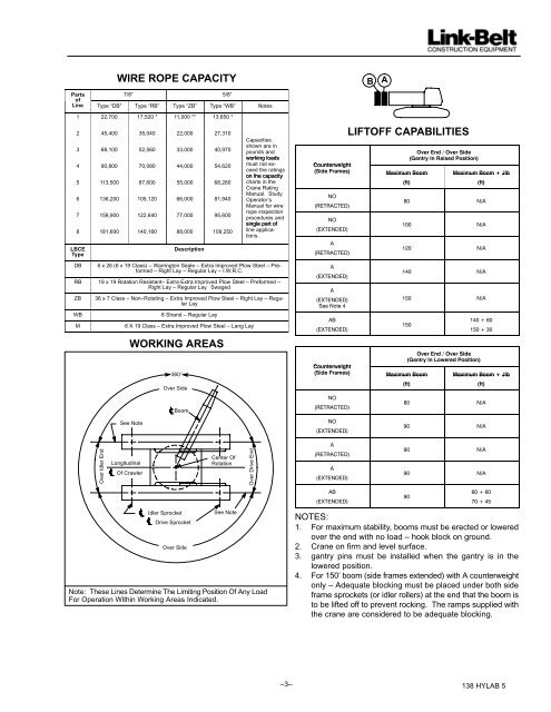
WIRE ROPE CAPACITY<br />
Parts 7/8” 5/8”<br />
of<br />
Line Type “DB” Type “RB” Type “ZB” Type “WB” Notes<br />
1 22,700 17,520 * 11,000 ** 13,650 *<br />
2 45,400 35,040 22,000 27,310<br />
3 68,100 52,560 33,000 40,970<br />
4 90,800 70,080 44,000 54,620<br />
5 113,500 87,600 55,000 68,280<br />
6 136,200 105,120 66,000 81,940<br />
7 158,900 122,640 77,000 95,600<br />
8 181,600 140,160 88,000 109,250<br />
LBCE<br />
Type<br />
Description<br />
Capacities<br />
shown are in<br />
pounds and<br />
working loads<br />
must not exceed<br />
the ratings<br />
on the capacity<br />
charts in the<br />
Crane Rating<br />
Manual. Study<br />
Operator’s<br />
Manual for wire<br />
rope inspection<br />
procedures and<br />
single part of<br />
line applications.<br />
DB 6 x 26 (6 x 19 Class) – Warrington Seale – Extra Improved Plow Steel – Preformed<br />
– Right Lay – Regular Lay – I.W.R.C.<br />
RB 19 x 19 Rotation Resistant– Extra Extra Improved Plow Steel – Preformed –<br />
Right Lay – Regular Lay. Swaged<br />
ZB 36 x 7 Class – Non–Rotating – Extra Improved Plow Steel – Right Lay – Regular<br />
Lay<br />
WB 8 Strand – Regular Lay<br />
M 6 X 19 Class – Extra Improved Plow Steel – Lang Lay<br />
Over Idler End<br />
Longitudinal<br />
Of Crawler<br />
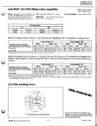
WORKING AREAS<br />
See Note<br />
360�<br />
Over Side<br />
Boom<br />
Idler Sprocket<br />
Drive Sprocket<br />
Over Side<br />
Center Of<br />
Rotation<br />
See Note<br />
Note: These Lines Determine The Limiting Position Of Any Load<br />
For Operation Within Working Areas Indicated.<br />
Over Drive End<br />
B<br />
A<br />
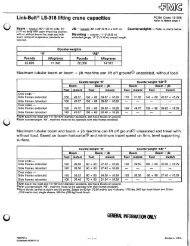
LIFTOFF CAPABILITIES<br />
��������������������<br />
���������������������������<br />
�������������<br />
�������������<br />
������������� � � ������������ ������������ ������������������<br />
������������������<br />
����<br />
����<br />
��<br />
�����������<br />
��<br />
����������<br />
�<br />
�����������<br />
�<br />
����������<br />
�<br />
����������<br />
����������<br />
��<br />
����������<br />
�� ���<br />
��� ���<br />
��� ���<br />
��� ���<br />
��� ���<br />
–3– <strong>138</strong> <strong>HYLAB</strong> 5<br />
���<br />
��������<br />
��������<br />
��������������������<br />
����������������������������<br />
�������������<br />
�������������<br />
������������� � � ������������ ������������ ������������������<br />
������������������<br />
����<br />
����<br />
��<br />
�����������<br />
��<br />
����������<br />
�<br />
�����������<br />
�<br />
����������<br />
��<br />
����������<br />
�� ���<br />
�� ���<br />
�� ���<br />
�� ���<br />
��<br />
�������<br />
�������<br />
NOTES:<br />
1. For maximum stability, booms must be erected or lowered<br />
over the end with no load – hook block on ground.<br />
2. Crane on firm and level surface.<br />
3. gantry pins must be installed when the gantry is in the<br />
lowered position.<br />
4. For 150’ boom (side frames extended) with A counterweight<br />
only – Adequate blocking must be placed under both side<br />
frame sprockets (or idler rollers) at the end that the boom is<br />
to be lifted off to prevent rocking. The ramps supplied with<br />
the crane are considered to be adequate blocking.