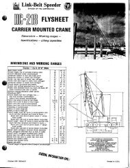
138 HYLAB 5 80–ton - Link-Belt Construction Equipment
138 HYLAB 5 80–ton - Link-Belt Construction Equipment
138 HYLAB 5 80–ton - Link-Belt Construction Equipment

Create successful ePaper yourself
Turn your PDF publications into a flip-book with our unique Google optimized e-Paper software.
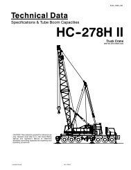
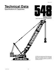
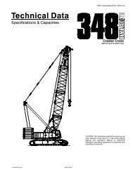
Technical Data<br />
Specifications & Angle Boom<br />
Capacities<br />
<strong>Link</strong>-<strong>Belt</strong> Cranes<br />
<strong>138</strong> <strong>HYLAB</strong> 5<br />
5439---0205---N9<br />
Crawler Crane<br />
80 Ton (72.6 metric ton)<br />
CAUTION: This material is supplied for reference use<br />
only. Operator must refer to in---cab Crane Rating<br />
Manual and Operator’s Manual to determine<br />
allowable crane lifting capacities and assembly and<br />
operating procedures.<br />
1
5439---0205---N9<br />
<strong>138</strong> <strong>HYLAB</strong> 5 <strong>Link</strong>-<strong>Belt</strong> Cranes
Table Of Contents<br />
<strong>Link</strong>-<strong>Belt</strong> Cranes<br />
<strong>138</strong> <strong>HYLAB</strong> 5<br />
5439---0205---N9<br />
Pages<br />
Specifications 1--12<br />
Angle Boom Capacities 1--12<br />
Angle Boom + Jib Capacities 1--20<br />
1
5439---0205---N9<br />
This page intentionally left blank<br />
<strong>138</strong> <strong>HYLAB</strong> 5 <strong>Link</strong>-<strong>Belt</strong> Cranes
Specifications<br />
Crawler Crane<br />
80 Ton (72.6 metric ton)<br />
CAUTION: This material is supplied for reference use<br />
only. Operator must refer to in---cab Crane Rating<br />
Manual and Operator’s Manual to determine<br />
allowable crane lifting capacities and assembly and<br />
operating procedures.<br />
1
19’ 7”<br />
(5.97m)<br />
8’ 4”<br />
(2.54m)<br />
4’ 1”<br />
(1.25m)<br />
14’ 1” (4.29m)<br />
Tailswing<br />
20’ 2”<br />
(6.15m)<br />
82˚ Boom<br />
Angle<br />
General Dimensions<br />
Tailswing of counterweight “A”<br />
1<br />
English Metric<br />
13’ 3” 4.04m<br />
Maximum live mast working height 30’ 9” 9.4m<br />
Boom foot pin diameter 3.5” 8.9cm<br />
Distance between inside of boom foot lugs 27” 0.7m<br />
5’ 10”<br />
(1.79m)<br />
40’ 0” (12.2m)<br />
Basic Boom<br />
10’ 8”<br />
(3.25m)<br />
36”<br />
(0.91m)<br />
Catwalks<br />
13’ 3” (4.05m)<br />
Cab Width<br />
10’ 6” (3.20m)<br />
17’ 0” (5.18m)<br />
Extended (Shown)<br />
11’ 11” (3.63m)<br />
Retracted<br />
15.2”<br />
(0.39m)
2<br />
<strong>138</strong> <strong>HYLAB</strong> 5 Crane Transport Weights -- approximate<br />
10’ 6” (3.20m)<br />
Cab Width<br />
11’ 11” (3.6m)<br />
Retracted<br />
Basic Unit<br />
Bare,noattachment,norope,nobackstops,<br />
catwalks on, 1/4 tank of fuel<br />
80,840 lb (36 668kg)<br />
3’ 3”<br />
(1.0m)<br />
6’ 11”<br />
(2.1m)<br />
3’ 10” (1.2m)<br />
Boom@ 0 Degrees<br />
16’ 10”<br />
(5.1m)<br />
21’ 1”<br />
(6.4m)<br />
20’ 2”<br />
(6.2m)<br />
6’ 0”<br />
(1.8m)<br />
11’ 11”<br />
(3.6m)<br />
36”<br />
(0.9m) 3’ 8”<br />
(1.1m)<br />
19.7”<br />
(0.5m)<br />
“A” Upper Counterweight<br />
25,250 lb (11 450kg)<br />
20’ 2”<br />
(6.2m)<br />
Side Frames w/ 36” (0.9m) Shoes<br />
18,380 lb (8 337kg)<br />
20.3”<br />
(0.5m)<br />
“B” Upper Counterweight<br />
25,250 lb (11 450kg)<br />
Front Mounted Third Drum<br />
1,345 lb (610kg) --- w/o Rope<br />
10’ 2” (3.1m)<br />
3’ 5”<br />
(1.0m)<br />
7’ 7”<br />
(2.3m)<br />
10’ 0”<br />
(3.0m)<br />
6’ 0”<br />
(1.8m)<br />
Transport Weight<br />
Rope on both drums, backstops, catwalks, and 1/3 tank of fuel<br />
Tubular: 89,778 lb (40 723kg)<br />
Angle: 90,678 lb (41 131kg)<br />
Upper & Carbody Shipping Weight<br />
Rope on both drums, backstops, catwalks, and full of fuel<br />
51,392 lb (23 311kg)<br />
4’ 0”<br />
(1.2m)<br />
2’ 9”<br />
(0.8m)<br />
22’ 7” (6.9m) 20’ 6” (6.3m)<br />
4’ 3”<br />
(1.3m)<br />
20’ (6.1m)TopSection<br />
Tubular: 2,700 lb (1 225kg)<br />
Angle: 3,500 lb (1 588kg)<br />
2’ 6”<br />
(0.8m)<br />
31’ 1” (9.5m)<br />
11’ 6”<br />
(3.5m)<br />
9’ 4”<br />
(2.9m)<br />
20’ (6.1m)BaseSection<br />
Tubular: 1,988 lb (902kg)<br />
Angle: 2,853 lb (1 294kg)<br />
30’ (9.1m) Basic Tubular Jib Assembly<br />
1,683 lb (763kg)<br />
10’ 2”<br />
(3.1m)
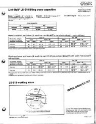
Transportation Weights<br />
Base Crane: Rigid Boom Backstops, 27 gal (102.2L) of Fuel, Catwalks (front, right, and left side), 20’ (6.10m) Tube Base Section, 24’ (7.32m)<br />
Live Mast with Bridle & Spreader Bar, 14---Part Boom Hoist Reeving, 700’ (213m) of Type “DB” Front Hoist Rope, 540’ (165m) ofType“RB”Rear<br />
Hoist Rope.<br />
Gross Weight Transport Loads<br />
Item Description<br />
lb kg<br />
Load<br />
#1<br />
Base Crane 89,778 40 723 1<br />
Add “A” Counterweight 25,250 11 453 1<br />
Add “B” Counterweight 25,250 11 453 1<br />
Add Hydraulic Third Drum Without Rope 1,345 610<br />
Add 20’ (6.1m) Tube Top Section 2,700 1 225 1<br />
Add 10’ (3.05m) Tube Extension With Pins & Pendants 677 307 1<br />
Load<br />
#2<br />
Load<br />
#3<br />
3<br />
Notes and Load Summary<br />
Numbers in the load columns to<br />
the left represent quantities.<br />
EEstimated ti t d transport t t load l d<br />
assumes the load out consist of<br />
200’ 200 (60.96m) of tube boom +<br />
60’ (18.29m) (18 29 ) off jib with i h full f ll<br />
counterweight<br />
counterweight.<br />
Add 20’ (6.1m) Tube Extension With Pins & Pendants 1,076 488 1 2 Support pp loads were targeted g at<br />
Add 30’ (9.1m) Tube Extension With Pins & Pendants<br />
Add 20’ (6.1m) Angle Base Section<br />
1,481<br />
2,853<br />
672<br />
1 294<br />
2 1<br />
45 45,000 000 lb (20 412kg), 412k ) 8’ 6”<br />
(2.6m) wide, 48’ (14.63m) long,<br />
and 13’ 13 6” 6 (4.11m) high highusinga using a<br />
Add 20’ (6.1m) Angle Top Section With 4 Lifting Sheaves<br />
Add 20’ (6.1m) Angle Top Section With 3 Lifting Sheaves<br />
3,500<br />
3,400<br />
1 588<br />
1 542<br />
ddrop deck d k ttrailer. il This Thi may vary<br />
depending on state laws laws, empty<br />
truck/trailer weights, and style<br />
Add 20’ (6.1m) Angle Top Section With 2 Lifting Sheaves 3,300 1 497<br />
of trailer.<br />
Add 10’ (3.05m) Angle Extension With Pins & Pendants 992 450<br />
Add 20’ (6.1m) Angle Extension With Pins & Pendants 1,625 737<br />
Add 30’ (9.1m) Angle Extension With Pins & Pendants 2,264 1 027<br />
Add Bridle & Spreader Bar Only (No Live Mast) 990 449<br />
Add Tagline Winder 760 345<br />
Add Fairleader 1,272 577<br />
Add 30’ (9.1m) Tube Jib 1,683 763 1<br />
Estimated weights vary by<br />
+/-- +/ 2%.<br />
Estimated Total Load #1<br />
89,778 lb (40 723kg).<br />
Estimated Total Load #2<br />
33 33,959 959 lb (15 404kg). 404kg)<br />
Add 15’ (4.6m) Tube Jib Extension 317 144 2 Estimated st ated Total ota Load oad #3<br />
Add 5’ (1.5m) Auxiliary Tip Extension 735 333<br />
31 31,877 877 lb (14 459kg). 459k )<br />
Add Holding Rope -- 0.88” X 165’ Type “DB” 234 106<br />
Add Closing Rope -- 0.88” X 220’ Type “DB” 312 142<br />
Add Inhaul Rope -- 0.88” X 105’ Type “M” 141 64<br />
Add Hoist Rope -- 0.88” x 210’ Type “DB” 298 135<br />
Add Jib Wire Rope -- 0.88” X 700’ Type “DB” 994 451<br />
Add 3rd Drum Wire Rope 0.63” X 385’ Type “ZB” 312 142<br />
Add 3rd Drum Wire Rope 0.63” X 385’ Type “WB” 296 134<br />
Add Auxiliary Lifting Bail 191 87<br />
Add 15--ton (13.6mt) Hook Ball -- Non Swivel 750 340 1<br />
Add 15--ton (13.6mt) Hook Ball -- Swivel 760 345<br />
Add 80--ton (72.6mt) 4 Sheave Hook Block 1,221 554 1<br />
Remove 20’ Tube Base Section --1,988 -902<br />
Remove Front Hoist Rope 0.88” X 700’ Type “DB” --944 -428<br />
Remove Jib Wire Rope 0.88” X 540’ Type “RB” --1,050 -476<br />
Remove 24’ (7.3m) Live Mast With Bridle & Spreader Bar --2,356 -1 069<br />
Add50gal(189.3L) Of Fuel 362 164<br />
Working Weights<br />
Option Description<br />
1<br />
2<br />
3<br />
4<br />
Base crane equipped with 40’ (12.2m) of tubular boom, live mast, “A” counterweight, 700’ (213m) front hoist rope,<br />
540’ (165m) rear hoist rope, 80--ton (72.6mt) hook block, 77 gal (291.5L) of fuel, and a 200 lb (90.7kg) operator.<br />
Option #1 plus “B” counterweight, midpoint pendants, and 160’ (48.77m) of boom extensions to obtain 200’<br />
(60.96m) of main boom.<br />
Option #2 plus 60’ (18.29m) of jib and 15--ton (13.6mt) hookball -- subtract 20’ (6.10m) of boom extension and<br />
midpoint pendants to obtain maximum 180’ + 60’ (54.86 + 18.29m) of main boom + jib.<br />
Base crane equipped with 40’ (12.20m) of angle boom, live mast, “A” counterweight, 700’ (213m) front hoist rope,<br />
540’ (165m) rear hoist rope, 80--ton (72.6mt) hook block, 77 gal (291.5L) of fuel, and a 200 lb (90.7kg) operator.<br />
5 Option #4 plus “B” counterweight and 110’ (33.53m) of boom extensions to obtain 150’ (45.72m) of main boom.<br />
6<br />
Option #5 plus 60’ (18.29m) of jib and 15--ton (13.6mt) hookball to obtain maximum 150’ + 60’ (45.72 + 18.29m) of<br />
main boom + jib.<br />
Notes:<br />
1. Ground bearing pressure is based on the total weight distributed evenly over the track contact area.<br />
2. Total contact area for 36” (0.91m) track shoes is 15,692 in2 (101,239cm2 ).<br />
Gross<br />
Weight<br />
lb (kg)<br />
119,511<br />
(54 209)<br />
153,109<br />
(69 449)<br />
155,100<br />
(70 352)<br />
121,176<br />
(54 965)<br />
155,196<br />
(70 396)<br />
158,263<br />
(71 786)<br />
Ground Bearing<br />
Pressure<br />
psi (kg/cm 2 )<br />
7.62<br />
(0.53)<br />
9.76<br />
(0.69)<br />
9.88<br />
(0.70)<br />
7.72<br />
(0.54)<br />
9.89<br />
(0.70)<br />
10.09<br />
(0.71)
4<br />
Attachment Options<br />
J 40’ -200’ Tube Boom<br />
(12.19 - 60.96m)<br />
Basic Tube Boom -- 40’ (12.19m)<br />
two--piece design that utilizes a 20’<br />
(6.10m) base section and a 20’ (6.10m)<br />
open throat top section with in--line<br />
connecting pins on 54” (1.37m) wide and<br />
44” (1.12m) deep centers.<br />
S Boom foot on 50” (1.27m) centers<br />
S 3” (76.2mm) diameter chords<br />
S Lugs on base section to attach carrying<br />
links<br />
S Skywalk platform<br />
S Deflector roller on top section<br />
S Permanent skid pads mounted on top<br />
section to protect head machinery<br />
S Rigid sheave guards<br />
S Five 18” (0.46m) root diameter steel<br />
sheaves mounted on sealed anti--friction<br />
bearings<br />
S Mechanical boom angle indicator<br />
Optional -- Handling system that mounts<br />
in the boom base to allow loading/unloading<br />
of a counterweight or a boom<br />
section onto transport trailers.<br />
Tube Boom Extensions -- The following<br />
table provides the lengths available and<br />
the suggested quantity to obtain<br />
maximum boom in 10’ (3.05m)<br />
increments. Midpoint pendant<br />
connections are required at 80’ (24.38m)<br />
for 190’ (57.91m) and 200’ (60.96m)<br />
boom lengths.<br />
Tube Boom<br />
Extensions<br />
Suggested Quantity for<br />
Maximum Boom<br />
10’ (3.05m) 1<br />
20’ (6.10m) 3<br />
30’ (9.14m) 3<br />
S Deflector roller on top of each section<br />
S Appropriate length pendants<br />
S Maximum tube boom tip height of 204’<br />
(62.18m)<br />
J 40’ -150’ Angle Boom<br />
(12.19 - 45.72m)<br />
Basic Angle Boom -- 40’ (12.19m)<br />
two--piece design that utilizes a 20’<br />
(6.10m) base section and a 20’ (6.10m)<br />
open throat top section with in--line<br />
connecting pins. Boom extensions are<br />
48” (1.22m) wide and 48” (1.22m) deep<br />
at outside dimensions of angles.<br />
S Boom foot on 50” (1.27m) centers<br />
S 4” X 4” X 0.38” (101.6 x 101.6 x 9.7mm)<br />
angle chords<br />
S Lugs on base section to attach carrying<br />
links<br />
S Skywalk platform<br />
S Deflector roller on top section<br />
S Permanent skid pads mounted on top<br />
section to protect head machinery<br />
S Rigid sheave guards<br />
S Four 18” (0.46m) root diameter steel<br />
sheaves mounted on sealed antifriction<br />
bearings<br />
S Mechanical boom angle indicator<br />
Optional -- Three sheave head<br />
machinery for clam applications or two<br />
wide sheaves for dragline applications<br />
Angle Boom Extensions -- The<br />
following table provides the lengths<br />
available and the suggested quantity to<br />
obtain maximum boom in 10’ (3.05m)<br />
increments. Midpoint pendant<br />
connections are not required.<br />
Angle Boom<br />
Extensions<br />
Suggested Quantity for<br />
Maximum Boom<br />
10’ (3.05m) 1<br />
20’ (6.10m) 2<br />
30’ (9.14m) 2<br />
S Deflector roller on top of each section<br />
S Appropriate length pendants<br />
S Maximum angle boom tip height of 154’<br />
(46.94m)<br />
J 30’ - 60’ Tube Jib<br />
(9.14- 18.29m)<br />
Basic Tube Jib -- 30’ (9.14m) two--piece<br />
design that utilizes a 15’ (4.57m) base<br />
section and a 15’ (4.57m) top section<br />
with in--line connecting pins on 32”<br />
(0.81m) wide and 24” (0.61m) deep<br />
centers.<br />
S 2” (50.8mm) diameter tubular chords<br />
S One 18.5” (0.47m) root diameter steel<br />
sheave mounted on sealed anti--friction<br />
bearings.<br />
S 15’ (4.57m) jib extensions provide jib<br />
lengths at 45’ (13.72m) and 60’<br />
(18.29m)<br />
S Jib offset angles at 5˚, 15˚, and 25˚<br />
S Maximum tip height of boom + jib is 242’<br />
(73.76m) using the tube boom and 204’<br />
(62.18m) using the angle boom.<br />
J Auxiliary 5’ (1.52m)<br />
Tip Extension<br />
Designed to use instead of a jib to<br />
provide clearance between working hoist<br />
lines. The extension is equipped with a<br />
single 15.25” (0.39m) root diameter steel<br />
sheave mounted on sealed anti--friction<br />
bearings. Maximum capacity is 9--ton<br />
(8.16mt).<br />
J Boom Hoist System<br />
Designed to lift off maximum boom or<br />
maximum boom plus jib unassisted.<br />
Operates up to a maximum boom angle<br />
of 82˚. Automatically limits maximum<br />
boom angle operation.<br />
S Retractable gantry frame<br />
S Pin--on bail frame<br />
S 14--part reeving with 5/8” (15.88mm)<br />
type “W” wire rope<br />
S Bridle assembly<br />
S 24’ (7.31m) live mast (optional for angle<br />
attachment)<br />
S Two 1.25” (31.75mm) pendants<br />
S Telescopic boom backstops (tubular<br />
type)<br />
S Sheaves contain sealed anti--friction<br />
bearings<br />
S Boom speed from 10_-- 70_ is 52 seconds<br />
with no load and 94 seconds with<br />
full load. Speed was determined using<br />
100’ (30.5m) of tube boom.
Revolving Upperstructure<br />
J Frame<br />
All welded steel frame with precision<br />
machined surfaces for mating parts.<br />
J Engine<br />
Mitsubishi 6D16--TLE2A with oil filter, oil cooler,<br />
air cleaner, fuel filter, water separator, hour meter,<br />
tachometer, and electrical shutdown.<br />
Number of cylinders 6<br />
Bore and stroke -- in<br />
(mm)<br />
4.65 x 4.53<br />
(118 x 115)<br />
Piston displacement -- in3 (cm3 ) 460 (7 538)<br />
Engine rpm at full load speed 2,000<br />
Hi--idle rpm 2,200<br />
Gross horsepower (kw) 182 (135)<br />
Peak torque -- ft lb (joule) 535 (726)<br />
Peak torque -- rpm 1,600<br />
Electrical system 24 volt<br />
Batteries 2--12 volt<br />
Approximate fuel consumption gal/hr (L/hr)<br />
100% hp 9.17 (34.71)<br />
50% hp 4.58 (17.34)<br />
25% hp 2.29 (8.67)<br />
15% hp 1.38 (5.22)<br />
J Hydraulic System<br />
Hydraulic Pumps -- The pump<br />
arrangement is designed to provide<br />
precise control with independent or<br />
simultaneous operation of all crane<br />
functions.<br />
S Pump P1 -- Variable displacement,<br />
semi--closed loop, piston pump<br />
operating at 4,480 psi (315kg/cm 2 ) and<br />
64 gpm (242Lpm). Supplies power for<br />
the front drum, rear drum, boom hoist<br />
drum, and travel.<br />
S Pump P2 -- Variable displacement,<br />
semi--closed loop, piston pump<br />
operating at 4,480 psi (315kg/cm 2 ) and<br />
64 gpm (242Lpm). Supplies power for<br />
the front drum, rear drum, travel, and<br />
optional 4th drum.<br />
S Pump P3 -- Fixed displacement, open<br />
loop, gear pump operating at 3,556 psi<br />
(250kg/cm 2 ) and 33 gpm (125Lpm).<br />
Supplies power for swing and side<br />
frame retract cylinders.<br />
S Pump P4 -- Fixed displacement, open<br />
loop, gear pump operating at 1,422 psi<br />
(100kg/cm 2 ) and 12.7 gpm (48Lpm).<br />
Supplies power for remote mounted<br />
hydraulic oil cooler fan.<br />
S Pump P5 -- Fixed displacement, open<br />
loop, gear pump operating at 2,987 psi<br />
(210kg/cm 2 ) and 8.6 gpm (33Lpm).<br />
Supplies power for hydraulic remote<br />
control system and hydraulic<br />
counterweight self--assembly system.<br />
S Pump P6 (Optional) -- Fixed<br />
displacement, open loop, gear pump<br />
operating at 1,422 psi (100kg/cm 2 ) and<br />
6.3 gpm (24Lpm). Supplies power for<br />
optional hydraulic tagline.<br />
Pump Control (“Fine Inching”) mode<br />
Special pump setting, selectable from<br />
operator’s cab, that allows very slow<br />
movements of load hoist drums, boom<br />
hoist drum, and travel for precision work.<br />
Hydraulic Reservoir -- 53 gal (200.6L),<br />
equipped with sight level gauge.<br />
Diffusers built in for deaeriation.<br />
Filtration -- One 10 micron, full flow line<br />
filter in the control circuit. All oil is filtered<br />
prior to entering the reservoir.<br />
Counterbalance Valves -- All hoist<br />
motors are equipped with<br />
counterbalance valves to provide<br />
positive load lowering and prevent<br />
accidental load drop if the hydraulic<br />
pressure is suddenly lost.<br />
J Load Hoist Drums<br />
Each drum contains a pilot controlled,<br />
bi--directional, axial piston motor and a<br />
planetary gear reduction unit to provide<br />
positive control under all load conditions.<br />
S Power up/down & free--fall operation<br />
modes<br />
S Automatic brake mode (spring applied,<br />
hydraulically released, band type<br />
brake)<br />
S 0.88” (22.35mm) grooved lagging<br />
S Drum pawl controlled manually<br />
S Electronic drum rotation indicators<br />
S Mounted on anti--friction bearings<br />
S 17.64” (0.45m) root diameter<br />
S 29.92” (0.76m) flange diameter<br />
S 19.84” (0.50m) width<br />
Note: The freefall operation mode is<br />
designed to prevent load lowering even if<br />
the freefall switch is accidentally<br />
activated. The automatic brake mode<br />
meets all OSHA requirements for<br />
personnel handling.<br />
Drum Clutches -- Power hydraulic two<br />
shoe clutch design that uses a 20”<br />
(0.51mm) diameter x 5” (0.13mm) wide<br />
shoe that internally expands to provide<br />
load control. Swept area is 314 in2 (2 026 cm2 ).<br />
5<br />
J Optional Front<br />
Mounted Third Hoist<br />
Drum<br />
The hydraulic winch is pinned to the front<br />
of the upper frame and is used in<br />
conjunction with a fleeting sheave and<br />
3--sheave idler assembly to run the wire<br />
rope over the boom top section.<br />
S Free--spooling capability for pile<br />
driving applications<br />
S 10.63” (0.27m) root diameter<br />
S 20” (0.51m) outside flange diameter<br />
S 13.5” (0.34m) width<br />
S Mounted on anti--friction bearings<br />
J Boom Hoist Drum<br />
Contains a pilot controlled, bi--directional,<br />
axial piston motor and a planetary gear<br />
reduction unit to provide positive control<br />
under all load conditions.<br />
S Spring applied, hydraulically released,<br />
disc type automatically controlled brake<br />
S 5/8” (15.88mm) grooved lagging<br />
S Drum pawl controlled manually<br />
S Mounted on anti--friction bearings<br />
S 12.60” (0.32m) root diameter<br />
S 24.41” (0.62m) flange diameter<br />
S 9.57” (0.24m) width<br />
J Swing System<br />
Mechanical linkage controls the<br />
bi--directional axial piston motor and the<br />
planetary gear reduction unit to provide<br />
positive control under all load conditions.<br />
S Spring applied, hydraulically released,<br />
360 degree multi--plate brake<br />
S Free swing mode when lever is in neutral<br />
position<br />
S Two position positive house lock<br />
S Audio/Visual swing alarm<br />
S Maximum swing speed is 3.0 rpm<br />
J Upper Counterweight<br />
Consist of a two piece design that can<br />
be easily lowered to the ground using<br />
the gantry.<br />
S 25,250 lb (11 453kg) “A” upper<br />
counterweight<br />
S 25,250 lb (11 453kg) “B” upper<br />
counterweight can be added to<br />
maximize capacities
6<br />
J Operator’s Cab and<br />
Controls<br />
Fully enclosed modular steel compartment<br />
is independently mounted and insulated<br />
to protect against vibration and<br />
noise.<br />
S All tinted/tempered safety glass<br />
S Folding hinge entry door and sliding<br />
front glass window<br />
S 19,000 BTU hot water heater<br />
S 18,600 BTU air conditioner<br />
S Door and window locks<br />
S Circulating fan<br />
S Sun visor<br />
S Cloth seat<br />
S Padded for noise and vibration reduction<br />
S Defroster<br />
S Windshield wipers and washer<br />
S Dry chemical fire extinguisher<br />
S Engine instrumentation panel (voltmeter,<br />
engine oil pressure, engine water<br />
temperature, fuel level, hydraulic oil<br />
temperature, hour meter, and service<br />
monitor system)<br />
S Electronic drum rotation indicators for<br />
front and rear hoist drums<br />
S Six way adjustable seat<br />
S Hand and foot throttle<br />
S Fully adjustable single axis controls<br />
S Swing lever with swing brake and horn<br />
located on handle<br />
S Bubble type level<br />
S Ergonomic gauge layout<br />
S Control shut off lever<br />
S Right hand control stand is adjustable<br />
by electric motor for operator comfort<br />
S Horn<br />
Lower Structure<br />
J Lower Frame<br />
All welded box construction frame with<br />
precision machined surfaces for<br />
turntable bearing and rotating joint.<br />
S 8’ 10.7” (2.71m) overallwidth<br />
S 11’ 11” (3.63m) overall length<br />
J Rated Capacity<br />
Limiter System<br />
The rated capacity limiter system is a<br />
boom hoist load cell system. This system<br />
provides the operator with useful<br />
geometrical data, to include:<br />
S Main Boom Length<br />
S Main Boom Angle<br />
S Jib Length<br />
S Jib Angle<br />
S Operating Mode<br />
S Load Radius<br />
S Boom Tip Height<br />
S Audible Alarm<br />
S Anti--Two Block Indicator<br />
S Pre--Warning Light<br />
S Overload Light<br />
S Load On Hook<br />
S Function kick--outs including over load<br />
S Operator settable stops (Ramped<br />
Stops)<br />
S Boom Hoist Dead End Load Cell (No<br />
Lineriders)<br />
S Engine rpm Is Displayed On LCD1 Of<br />
Rated Capacity Limiter System<br />
J Side Frames<br />
All welded, precision machined, steel<br />
frames can be hydraulically extended<br />
and retracted by a hydraulic cylinder<br />
mounted in the lower frame.<br />
S 14’ (4.27m) extended gauge<br />
S 8’ 11” (2.72m) retracted gauge<br />
S 20’ 2” (6.15m) overall length<br />
S 36” (0.91m) wide track shoes<br />
S 11 sealed (oil filled) track rollers per side<br />
frame<br />
S Sealed (oil filled) idler and drive<br />
planetaries<br />
S Compact travel drives<br />
S Hydraulic self adjusting tracks<br />
J Additional <strong>Equipment</strong><br />
- Standard<br />
S 57.88” (1.47m) outside diameter<br />
turntable bearing<br />
S Front, right, & left side removable<br />
catwalks<br />
S 53 gal (200.6L) fuel tank<br />
(usable quantity)<br />
S Crane lifting links<br />
J Additional <strong>Equipment</strong><br />
- Optional<br />
S Rud--o--matic R model 1248 tagline<br />
winder for angle boom (double barrel,<br />
spring wound, drum type)<br />
S Rud--o--matic R model 648 tagline<br />
winder for tube boom<br />
S Full revolving type Fairleader with<br />
barrel, sheaves, and guide rollers<br />
Travel and Steering -- Each side frame<br />
contains a pilot controlled, bi--directional,<br />
axial piston motor and a planetary gear<br />
reduction unit to provide positive control<br />
under all load conditions.<br />
S Individual control provides smooth,<br />
precise maneuverability including full<br />
counter--rotation<br />
S Spring applied, hydraulically released<br />
disc type automatically controlled<br />
brake<br />
S Maximum travel speed is 1.0 mph<br />
(1.6km/h) in high speed and 0.6 mph<br />
(1km/h) in low speed<br />
S Designed to 30% gradeability
Load Hoisting Performance<br />
FrontOrRearDrum---7/8”(22.22mm) WireRope<br />
Rope<br />
Maximum Line Pull No Load Line Speed Full Load Line Speed Pitch Diameter Layer Total<br />
Layer lb kg ft/min m/min ft/min m/min in mm ft m ft m<br />
1 32,377 14 686 300 91 91 28 18.5 470 100 30 100 30<br />
2 29,581 13 418 329 100 100 30 20.3 516 109 33 209 64<br />
3 27,229 12 351 357 109 109 33 22.0 559 119 36 327 100<br />
4 25,224 11 441 386 118 117 36 23.8 605 128 39 455 139<br />
5 23,493 10 657 414 126 126 38 25.5 648 137 42 593 181<br />
6 21,985 9 972 442 135 134 41 27.3 693 147 45 740 225<br />
Boom Hoist Drum --- 5/8” (15.88mm) WireRope<br />
Rope<br />
Maximum Line Pull No Load Line Speed Full Load Line Speed Pitch Diameter Layer Total<br />
Layer lb kg ft/min m/min ft/min m/min in mm ft m ft m<br />
1 17,856 8 099 186 57 177 54 13.2 336 48 15 48 15<br />
2 16,313 7 400 203 62 193 59 14.5 368 52 16 100 31<br />
3 15,017 6 812 221 67 210 64 15.7 400 57 17 157 48<br />
4 13,911 6 310 238 73 227 69 17.0 432 61 19 218 67<br />
5 12,956 5 877 256 78 243 74 18.3 464 66 20 284 87<br />
6 12,125 5 500 274 84 260 79 19.5 496 70 21 355 108<br />
7 11,393 5 168 291 89 277 84 20.8 528 75 23 430 131<br />
Optional Third Drum --- 5/8” (15.88mm) WireRope<br />
Rope<br />
Maximum Line Pull No Load Line Speed Full Load Line Speed Pitch Diameter Layer Total<br />
Layer lb kg ft/min m/min ft/min m/min in mm ft m ft m<br />
1 15,041 6 822 157 48 143 44 11.25 286 57 17 57 17<br />
2 13,537 6 140 175 53 159 48 12.50 318 64 20 121 37<br />
3 12,307 5 582 192 59 175 53 13.75 349 71 22 192 59<br />
4 11,282 5 117 210 64 191 58 15.00 381 77 23 269 82<br />
5 10,414 4 724 228 69 207 63 16.25 413 83 25 352 107<br />
6 9,671 4 387 245 75 223 68 17.50 445 90 27 442 135<br />
Wire Rope Applications<br />
Wire Rope Application<br />
Diameter Length<br />
in mm ft m<br />
Type<br />
Maximum Permissible Load<br />
lb kg<br />
Boom Hoist 5/8 15.88 610 186 W 11,770 5 339<br />
Front Hoist 7/8 22.22 700 213 DB 22,740 10 315<br />
Rear Hoist (Optional) 7/8 22.22 540 165 RB 17,520 7 947<br />
Rear Hoist (Optional) 7/8 22.22 700 213 DB 22,740 10 315<br />
Third Drum (Optional) 5/8 15.88 385 117 ZB 11,080 5 026<br />
Third Drum (Optional) 5/8 15.88 385 117 WB 13,650 6 192<br />
Rope<br />
Type<br />
Description<br />
DB 6 x 26 (6 X 19 Class) --- Warrington Seal --- Extra Improved Plow Steel --- Preformed --- Right Lay --- Regular Lay --- I.W.R.C.<br />
RB 19 x 19 Rotation Resistant --- Extra Improved Plow Steel --- Preformed --- Right Lay --- Regular Lay --- Swaged<br />
ZB 36 x 7 --- Non --- rotating --- Extra Improved Plow Steel --- Right Lay --- Regular Lay<br />
WB 8 Strand --- Regular Lay<br />
W 6 x 26 (6 X 19 Class) --- Extra Improved Plow Steel --- Preformed --- Right Lay --- Alternate Lay --- I.W.R.C.<br />
7
8<br />
This Page Left Blank<br />
Intentionally
This Page Left Blank<br />
Intentionally<br />
9
<strong>Link</strong> -<strong>Belt</strong> <strong>Construction</strong> <strong>Equipment</strong> Company Lexington, Kentucky www.linkbelt.com<br />
R<strong>Link</strong>--<strong>Belt</strong> is a registered trademark. Copyright 2005. We are constantly improving our products and therefore reserve the right to change designs and specifications.
������������������<br />
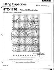
Lattice Boom Crawler Crane<br />
<strong>138</strong> <strong>HYLAB</strong> 5 <strong>80–ton</strong> (72.6 metric ton)<br />
Angle Boom Capacities<br />
40’ – 150’ (12.19 – 45.72m)<br />
24’ (7.31m) Live Mast<br />
� Extended/Retracted Side Frames<br />
5’ (1.52m) Tip Extension<br />
Duty Cycle Capacities<br />
� 40’ – 70’ (12.19 – 21.34m) Angle Boom<br />
� Extended Side Frames<br />
� “A” Counterweight<br />
Angle Boom Capacities<br />
� 40’ – 150’ (12.19 – 45.72m) Angle Boom<br />
� 48” (1.22m) Wide x 48” (1.22m) Deep Boom<br />
� 20’ (6.10m) Open Throat Top Section<br />
� �������������������������������������<br />
� Extended / Retracted Side Frames<br />
� Over End Blocked Capacities<br />
� “AB”, “A”, or “0” Counterweight Options<br />
� 20’ 2” (6.15m) Crawler Length<br />
CAUTION: This material is supplied for reference use only. Operator must refer to<br />
in–cab Crane Rating Manual to determine allowable crane lifting capacities and<br />
operating procedures.
<strong>138</strong> <strong>HYLAB</strong> 5<br />
�������<br />
����� ���� ����������� ���� ����������� ���� ������� �������� ���� ���<br />
�������������������������������������������������������������������<br />
�������������������������������������������������������������������<br />
���������<br />
LIFTING NOTES<br />
GENERAL:<br />
1. Rated lifting capacities in pounds as shown on lift<br />
charts pertain to this crane as originally manufactured<br />
and normally equipped. Modifications to the crane or<br />
use of optional equipment other than that specified<br />
can result in a reduction of capacity.<br />
2. <strong>Construction</strong> equipment can be dangerous if<br />
improperly operated or maintained. Operation and<br />
maintenance of this crane must be in compliance with<br />
the information in the Operator’s, Parts, and Safety<br />
Manuals supplied with this crane. If these manuals<br />
are missing, order replacements through the<br />
distributor.<br />
3. The operator and other personnel associated with this<br />
crane shall read and fully understand the latest<br />
applicable American National Standards Institute<br />
(ANSI) safety standards for cranes.<br />
4. All capacities listed in this book are in compliance with<br />
ASME/ANSI B30.5c at date of manufacture.<br />
LIFT CRANE OPERATION:<br />
1. Capacities shown are in pounds and are not more<br />
than 75% of the tipping loads with the crane standing<br />
level on firm supporting surface. A deduction must be<br />
made from these capacities for weight of hook block,<br />
hook ball, sling, grapple, load weighing device (other<br />
than those supplied with the crane), etc. When using<br />
main hook while jib is attached, reduce capacities by<br />
values shown on Capacity Deductions For Lifting Off<br />
Main Boom Hook With Jib Installed. When using main<br />
hook while 5’ tip extension is attached, reduce<br />
capacities by values shown on Capacity Deductions<br />
For Lifting Off Main Boom Hook With 5’<br />
2.<br />
Tip Extension Installed. See Operator’s Manual for all<br />
limitations when raising or lowering attachment.<br />
The crane capacities in the shaded areas are based<br />
on structural strength. The crane capacities in the<br />
non–shaded areas are based on stability.<br />
–2–<br />
3. For recommended reeving, parts of line, wire rope<br />
type, and wire rope inspection, see Wire Rope<br />
Capacity chart, Operator’s Manual, and Parts<br />
Manual.<br />
4. Load ratings in the Crane Rating Manual are based on<br />
freely suspended loads and make no allowances for<br />
such factors as the effect of the wind, ground<br />
conditions, and operating speeds. The operator shall<br />
therefore reduce load ratings in order to take these<br />
conditions into account.<br />
5. Rated lifting capacities do not account for the effects<br />
of wind on a suspended load or boom. Lifting<br />
capacities should be considered acceptable for wind<br />
speeds less than 20 mph and appropriately reduced<br />
for wind speeds greater than 20 mph. Extreme<br />
caution should be used when lifting heavy loads or<br />
loads with large wind sail area under high wind<br />
conditions (over 20 mph).<br />
6. The capacities listed in the Crane Rating Manual are<br />
for the crane with or without live mast, with the gantry<br />
in the raised position.<br />
7. The least stable rated condition is over the side.<br />
8. Booms must be erected and lowered over the end for<br />
maximum stability.<br />
9. Do not operate at radii and boom lengths where the<br />
Crane Rating Manual lists no capacity. Do not use<br />
longer booms or jibs than those listed in the Crane<br />
Rating Manual. Any of the above can cause a tipping<br />
condition or boom and jib failure.<br />
10. These capacities apply only to the crane as originally<br />
manufactured and normally equipped by <strong>Link</strong>–<strong>Belt</strong><br />
<strong>Construction</strong> <strong>Equipment</strong> Company.<br />
FOR OVER END CAPACITIES ONLY<br />
1. These capacities can be lifted over either end with the<br />
crane standing level on a firm supporting surface with<br />
adequate blocking placed under the side frame<br />
sprockets/idlers, to prevent rocking.<br />
2. Do not travel with a load.
WIRE ROPE CAPACITY<br />
Parts 7/8” 5/8”<br />
of<br />
Line Type “DB” Type “RB” Type “ZB” Type “WB” Notes<br />
1 22,700 17,520 * 11,000 ** 13,650 *<br />
2 45,400 35,040 22,000 27,310<br />
3 68,100 52,560 33,000 40,970<br />
4 90,800 70,080 44,000 54,620<br />
5 113,500 87,600 55,000 68,280<br />
6 136,200 105,120 66,000 81,940<br />
7 158,900 122,640 77,000 95,600<br />
8 181,600 140,160 88,000 109,250<br />
LBCE<br />
Type<br />
Description<br />
Capacities<br />
shown are in<br />
pounds and<br />
working loads<br />
must not exceed<br />
the ratings<br />
on the capacity<br />
charts in the<br />
Crane Rating<br />
Manual. Study<br />
Operator’s<br />
Manual for wire<br />
rope inspection<br />
procedures and<br />
single part of<br />
line applications.<br />
DB 6 x 26 (6 x 19 Class) – Warrington Seale – Extra Improved Plow Steel – Preformed<br />
– Right Lay – Regular Lay – I.W.R.C.<br />
RB 19 x 19 Rotation Resistant– Extra Extra Improved Plow Steel – Preformed –<br />
Right Lay – Regular Lay. Swaged<br />
ZB 36 x 7 Class – Non–Rotating – Extra Improved Plow Steel – Right Lay – Regular<br />
Lay<br />
WB 8 Strand – Regular Lay<br />
M 6 X 19 Class – Extra Improved Plow Steel – Lang Lay<br />
Over Idler End<br />
Longitudinal<br />
Of Crawler<br />
WORKING AREAS<br />
See Note<br />
360�<br />
Over Side<br />
Boom<br />
Idler Sprocket<br />
Drive Sprocket<br />
Over Side<br />
Center Of<br />
Rotation<br />
See Note<br />
Note: These Lines Determine The Limiting Position Of Any Load<br />
For Operation Within Working Areas Indicated.<br />
Over Drive End<br />
B<br />
A<br />
LIFTOFF CAPABILITIES<br />
��������������������<br />
���������������������������<br />
�������������<br />
�������������<br />
������������� � � ������������ ������������ ������������������<br />
������������������<br />
����<br />
����<br />
��<br />
�����������<br />
��<br />
����������<br />
�<br />
�����������<br />
�<br />
����������<br />
�<br />
����������<br />
����������<br />
��<br />
����������<br />
�� ���<br />
��� ���<br />
��� ���<br />
��� ���<br />
��� ���<br />
–3– <strong>138</strong> <strong>HYLAB</strong> 5<br />
���<br />
��������<br />
��������<br />
��������������������<br />
����������������������������<br />
�������������<br />
�������������<br />
������������� � � ������������ ������������ ������������������<br />
������������������<br />
����<br />
����<br />
��<br />
�����������<br />
��<br />
����������<br />
�<br />
�����������<br />
�<br />
����������<br />
��<br />
����������<br />
�� ���<br />
�� ���<br />
�� ���<br />
�� ���<br />
��<br />
�������<br />
�������<br />
NOTES:<br />
1. For maximum stability, booms must be erected or lowered<br />
over the end with no load – hook block on ground.<br />
2. Crane on firm and level surface.<br />
3. gantry pins must be installed when the gantry is in the<br />
lowered position.<br />
4. For 150’ boom (side frames extended) with A counterweight<br />
only – Adequate blocking must be placed under both side<br />
frame sprockets (or idler rollers) at the end that the boom is<br />
to be lifted off to prevent rocking. The ramps supplied with<br />
the crane are considered to be adequate blocking.
CAPACITY DEDUCTIONS FOR LIFTING<br />
OFF MAIN BOOM HOOK WITH JIB<br />
INSTALLED (OPEN THROAT BOOM ONLY)<br />
When using main boom hook, while jib is attached, reduce boom capacities<br />
by the values in the following chart:<br />
Jib Length (ft) Offset Angle (deg)<br />
Capacity Deduction<br />
(lb)<br />
5 3,700<br />
30<br />
15 4,800<br />
25 6,200<br />
5 4,500<br />
45<br />
15 6,400<br />
25 8,400<br />
5 5,500<br />
60<br />
15 7,900<br />
25 10,600<br />
CAPACITY DEDUCTIONS FOR LIFTING<br />
OFF MAIN BOOM HOOK WITH 5 FOOT TIP<br />
EXTENSION INSTALLED<br />
When using main boom hook, while 5 foot tip extension is attached, reduce boom capacities<br />
by the values in the following chart:<br />
<strong>138</strong> <strong>HYLAB</strong> 5<br />
Tip Extension Capacity Deduction (lb)<br />
5’ Tip Extension – Not Reeved 900<br />
5’ Tip Extension – With 15T<br />
Hook Ball<br />
2,200<br />
MAXIMUM ALLOWABLE CAPACITIES<br />
FOR 5’ TIP EXTENSION<br />
Lifting capacity to be the smallest of the following values:<br />
1. 18,000 lb<br />
2. The standard crane lift capacity minus 1,100 lb for the boom<br />
length, tip extension load radius, and counterweight<br />
configuration in use on the crane.<br />
Notes:<br />
1. All notes are to be adhered to as listed on the standard lift<br />
crane capacity charts.<br />
2. Reduce the main boom lift capacities by 1,100 lb when the<br />
tip extension is installed.<br />
3. The 5’ tip extension can be installed on the maximum boom<br />
length of 150’.<br />
4. Do not lift or suspend a load from the boom tip extension and<br />
main boom at the same time.<br />
20’ Open Throat Boom With 5’ Tip Extension<br />
–4–<br />
LIVE MAST LIFTING CAPACITIES<br />
(WITHOUT COUNTERWEIGHT<br />
INSTALLED)<br />
Radius<br />
(ft)<br />
Live Mast Side Frames Side Frames<br />
Angle<br />
Extended<br />
Retracted<br />
(deg)<br />
(lb)<br />
(lb)<br />
10 73.7 60,000 60,000<br />
11 71.2 60,000 51,600<br />
12 68.7 60,000 44,600<br />
13 66.1 60,000 39,200<br />
14 63.5 60,000 34,900<br />
15 60.8 59,400 31,500<br />
16 58.0 52,700 28,600<br />
17 55.1 47,400 26,200<br />
18 52.2 43,000 24,200<br />
19 49.1 39,300 22,500<br />
20 45.8 36,200 20,900<br />
21 42.4 33,500 19,600<br />
22 38.8 31,200 18,400<br />
23 34.8 29,200 17,300<br />
24 30.3 27,400 16,400<br />
Notes:<br />
1. Refer to the Operator’s Manual.<br />
2. Live mast backstops must be in position and operative.<br />
3. Use rear hoist drum only. Reeve hoist line to drum over live<br />
mast cross member.<br />
4. Reeve hoist rope with three (3) parts of 7/8” diameter wire<br />
rope.<br />
5. The crane shall be leveled on a firm supporting surface.<br />
6. Capacities are based on 75% stability.<br />
7. See Crane Assembly Component Weights chart for weight of<br />
components for crane assembly in the Crane Rating Manual.<br />
8. Rated capacities for 360� rotation.<br />
9. Gantry can be either in the raised or lowered position when<br />
lifting loads with the live mast. When the gantry is in the lowered<br />
position the backstay links must be pinned.<br />
10. Do not lower live mast below 3� angle with gantry in lowered<br />
position.
DUTY CYCLE NOTES FOR ANGLE BOOM<br />
1. The capacities included in the “Duty Cycle Capacities –<br />
Angle Boom” chart are the maximum allowable, and are<br />
based on crane standing level on firm supporting surface<br />
under ideal job conditions.<br />
2. Capacities are based on 75% of minimum tipping loads for<br />
dragline; 67.5% for clamshell.<br />
3. Weight of bucket plus load, must not exceed these<br />
capacities.<br />
4. Dragline operation is not recommended with boom angles<br />
less than 35�.<br />
5. Boom length for dragline/clamshell attachment operation<br />
should not exceed 70’.<br />
Boom<br />
Length<br />
(ft)<br />
Load<br />
Radius<br />
(ft)<br />
Boom<br />
Angle<br />
(deg)<br />
6. Retractable high gantry must be fixed in raised position for all<br />
capacities on the “Duty Cycle Capacities – Angle Boom”<br />
chart.<br />
7. These capacities apply to the crane as originally<br />
manufactured and normally equipped by <strong>Link</strong>–<strong>Belt</strong><br />
<strong>Construction</strong> <strong>Equipment</strong> Company.<br />
8. Capacities are maximum recommended by PCSA Standard<br />
#4. Operator must make allowances for soft or uneven<br />
supporting surfaces, rapid cycle operations, bucket suction,<br />
or other unfavorable conditions which may require smaller<br />
buckets for most efficient operation.<br />
DUTY CYCLE CAPACITIES – ANGLE BOOM<br />
Side Frames Extended – “A” Counterweight<br />
Only (All capacities listed are<br />
in pounds)<br />
Dragline<br />
Clamshell/Magnet<br />
40 9 81.8 – – – 22,700<br />
40 10 80.3 – – – 22,700<br />
40 11 78.9 – – – 22,700<br />
40 12 77.4 – – – 22,700<br />
40 13 75.9 – – – 22,700<br />
40 14 74.5 – – – 22,700<br />
40 15 73.0 – – – 22,700<br />
40 16 71.5 – – – 22,700<br />
40 17 69.9 – – – 22,700<br />
40 18 68.4 – – – 22,700<br />
40 19 66.9 – – – 22,700<br />
40 20 65.3 – – – 22,700<br />
40 25 57.1 22,700 22,700<br />
40 30 48.1 22,700 22,700<br />
40 35 37.5 22,700 22,700<br />
40 40 23.4 – – – 20,160<br />
50 11 81.1 – – – 22,700<br />
50 12 80.0 – – – 22,700<br />
50 13 78.8 – – – 22,700<br />
50 14 77.6 – – – 22,700<br />
50 15 76.4 – – – 22,700<br />
50 16 75.3 – – – 22,700<br />
50 17 74.1 – – – 22,700<br />
50 18 72.9 – – – 22,700<br />
50 19 71.7 – – – 22,700<br />
50 20 70.5 – – – 22,700<br />
50 25 64.3 – – – 22,700<br />
50 30 57.7 22,700 22,700<br />
50 35 50.6 22,700 22,700<br />
50 40 42.7 22,500 20,250<br />
50 50 20.9 – – – 14,670<br />
60 12 81.6 – – – 22,700<br />
60 13 80.7 – – – 22,700<br />
60 14 79.7 – – – 22,700<br />
60 15 78.7 – – – 22,700<br />
60 16 77.8 – – – 22,700<br />
60 17 76.8 – – – 22,700<br />
60 18 75.8 – – – 22,700<br />
Boom<br />
Length<br />
(ft)<br />
Load<br />
Radius<br />
(ft)<br />
Boom<br />
Angle<br />
(deg)<br />
Side Frames Extended –<br />
“A” Counterweight Only<br />
(All capacities listed are in<br />
pounds)<br />
Dragline<br />
Clamshell/<br />
Magnet<br />
60 19 74.8 – – – 22,700<br />
60 20 73.8 – – – 22,700<br />
60 25 68.8 – – – 22,700<br />
60 30 63.6 – – – 22,700<br />
60 35 58.1 22,700 22,700<br />
60 40 52.3 22,400 20,160<br />
60 50 38.9 16,300 14,670<br />
60 60 19.0 – – – 11,160<br />
70 14 81.2 – – – 22,700<br />
70 15 80.4 – – – 22,700<br />
70 16 79.5 – – – 22,700<br />
70 17 78.7 – – – 22,700<br />
70 18 77.9 – – – 22,700<br />
70 19 77.0 – – – 22,700<br />
70 20 76.2 – – – 22,700<br />
70 25 71.9 – – – 22,700<br />
70 30 67.6 – – – 22,700<br />
70 35 63.1 – – – 22,700<br />
70 40 58.4 22,200 19,980<br />
70 50 48.1 16,200 14,580<br />
70 60 35.9 12,400 11,160<br />
70 70 17.6 – – – 8,730<br />
80 15 81.6 – – – 22,700<br />
80 16 80.9 – – – 22,700<br />
80 17 80.1 – – – 22,700<br />
80 18 79.4 – – – 22,700<br />
80 19 78.7 – – – 22,700<br />
80 20 77.9 – – – 22,700<br />
80 25 74.2 – – – 22,700<br />
80 30 70.5 – – – 22,700<br />
80 35 66.6 – – – 22,700<br />
80 40 62.7 – – – 19,800<br />
80 50 54.3 16,000 14,400<br />
80 60 44.8 12,200 10,980<br />
80 70 33.5 9,600 8,640<br />
80 80 16.5 – – – 6,840<br />
–5– <strong>138</strong> <strong>HYLAB</strong> 5
Height in feet above ground<br />
160’<br />
150’<br />
140’<br />
130’<br />
120’<br />
110’<br />
100’<br />
90’<br />
80’<br />
70’<br />
60’<br />
50’<br />
40’<br />
30’<br />
20’<br />
10’<br />
0’<br />
<strong>138</strong> <strong>HYLAB</strong> 5<br />
10°<br />
20°<br />
160’<br />
30°<br />
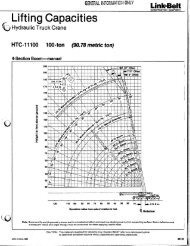
WORKING RANGE DIAGRAM<br />
����������������������������<br />
40°<br />
Minimum Boom Angle<br />
See Note 2.<br />
50°<br />
60°<br />
140’ 120’ 100’ 80’ 60’ 40’ 20’<br />
Operating radius from centerline of rotation in feet<br />
������<br />
1. Boom geometry shown is for unloaded condition and crane standing level on firm supporting surface. Boom<br />
deflection, subsequent radius, and boom angle change must be accounted for when applying load to hook.<br />
2. Maximum and minimum boom angles are equal to the values listed in the capacity chart for each boom<br />
length.<br />
–6–<br />
70°<br />
80°<br />
Maximum Boom Angle<br />
See Note 2.<br />
150’<br />
140’<br />
130’<br />
120’<br />
110’<br />
100’<br />
90’<br />
80’<br />
70’<br />
60’<br />
50’<br />
40’<br />
OF<br />
CL<br />
ROTATION<br />
Main Boom Length
Load Boom<br />
Radius<br />
(ft)<br />
MAIN BOOM CAPACITIES – 40 FT OPEN THROAT ANGLE BOOM<br />
Over<br />
End<br />
Blocked<br />
Angle<br />
(deg) AB<br />
CTWT<br />
(lb)<br />
AB<br />
CTWT<br />
(lb)<br />
B<br />
A<br />
Side Frames<br />
Extended<br />
A<br />
CTWT<br />
(lb)<br />
360� Rotation<br />
0<br />
CTWT<br />
(lb)<br />
Side Frames<br />
Retracted<br />
A<br />
CTWT<br />
(lb)<br />
0<br />
CTWT<br />
(lb)<br />
8.9 82.0 160,000 160,000 160,000 160,000 145,600 77,200<br />
9 81.8 160,000 160,000 160,000 160,000 140,700 74,600<br />
10 80.3 160,000 160,000 160,000 152,300 114,800 60,600<br />
11 78.9 160,000 160,000 156,700 119,900 96,800 50,900<br />
12 77.4 160,000 160,000 144,600 95,700 83,600 43,800<br />
13 75.9 151,200 151,200 134,100 79,500 73,500 38,300<br />
14 74.5 140,900 140,900 116,900 67,800 65,500 34,000<br />
15 73.0 132,000 132,000 102,000 59,100 59,000 30,500<br />
16 71.5 124,000 124,000 90,500 52,200 53,600 27,600<br />
17 69.9 117,000 117,000 81,200 46,800 49,100 25,200<br />
18 68.4 110,600 107,700 73,600 42,300 45,300 23,100<br />
19 66.9 104,900 98,600 67,300 38,600 42,000 21,300<br />
20 65.3 99,800 90,800 61,900 35,400 39,100 19,800<br />
25 57.1 79,600 64,900 44,000 24,800 28,900 14,300<br />
30 48.1 60,500 50,200 33,800 18,800 22,500 10,700<br />
35 37.5 48,500 40,600 27,100 14,800 18,200 8,300<br />
40 23.4 35,500 33,800 22,400 11,900 15,000 6,600<br />
Load Boom<br />
Radius<br />
(ft)<br />
MAIN BOOM CAPACITIES – 50 FT OPEN THROAT ANGLE BOOM<br />
Over<br />
End<br />
Blocked<br />
Angle<br />
(deg) AB<br />
CTWT<br />
(lb)<br />
AB<br />
CTWT<br />
(lb)<br />
Side Frames<br />
Extended<br />
A<br />
CTWT<br />
(lb)<br />
360� Rotation<br />
0<br />
CTWT<br />
(lb)<br />
Side Frames<br />
Retracted<br />
A<br />
CTWT<br />
(lb)<br />
0<br />
CTWT<br />
(lb)<br />
10.3 82.0 149,300 149,300 149,300 148,400 109,900 58,000<br />
11 81.1 146,200 146,200 146,200 120,200 96,800 50,900<br />
12 80.0 142,300 142,300 142,300 95,900 83,600 43,800<br />
13 78.8 <strong>138</strong>,700 <strong>138</strong>,700 133,700 79,600 73,400 38,300<br />
14 77.6 134,000 134,000 117,000 67,900 65,400 34,000<br />
15 76.4 130,800 130,800 102,100 59,100 58,900 30,500<br />
16 75.3 123,800 123,800 90,500 52,300 53,500 27,500<br />
17 74.1 116,800 116,800 81,200 46,800 49,000 25,100<br />
18 72.9 110,500 107,700 73,600 42,300 45,200 23,000<br />
19 71.7 104,800 98,500 67,300 38,500 41,900 21,200<br />
20 70.5 99,600 90,800 61,900 35,300 39,000 19,700<br />
25 64.3 79,600 64,800 43,900 24,700 28,700 14,100<br />
30 57.7 60,400 50,100 33,700 18,700 22,500 10,700<br />
35 50.6 48,500 40,600 27,100 14,800 18,200 8,400<br />
40 42.7 40,300 33,900 22,500 12,000 15,100 6,700<br />
50 20.9 27,100 25,100 16,300 8,300 10,900 4,300<br />
Load Boom<br />
Radius<br />
(ft)<br />
MAIN BOOM CAPACITIES – 60 FT OPEN THROAT ANGLE BOOM<br />
Over<br />
End<br />
Blocked<br />
Angle<br />
(deg) AB<br />
CTWT<br />
(lb)<br />
AB<br />
CTWT<br />
(lb)<br />
Side Frames<br />
Extended<br />
A<br />
CTWT<br />
(lb)<br />
360� Rotation<br />
0<br />
CTWT<br />
(lb)<br />
Side Frames<br />
Retracted<br />
A<br />
CTWT<br />
(lb)<br />
0<br />
CTWT<br />
(lb)<br />
11.7 82.0 130,200 130,200 130,200 103,800 87,900 46,100<br />
12 81.6 129,000 129,000 129,000 96,100 83,500 43,700<br />
13 80.7 125,900 125,900 125,900 79,700 73,300 38,200<br />
14 79.7 122,800 122,800 117,000 68,000 65,300 33,800<br />
15 78.7 120,000 120,000 102,100 59,100 58,800 30,300<br />
16 77.8 117,300 117,300 90,500 52,300 53,400 27,400<br />
17 76.8 114,700 114,700 81,200 46,700 48,900 25,000<br />
18 75.8 110,100 107,700 73,600 42,200 45,000 22,900<br />
19 74.8 104,500 98,500 67,200 38,500 41,700 21,100<br />
20 73.8 99,400 90,700 61,800 35,300 38,800 19,500<br />
25 68.8 79,500 64,700 43,800 24,600 28,500 13,900<br />
30 63.6 60,300 49,900 33,600 18,500 22,300 10,500<br />
35 58.1 48,300 40,400 27,000 14,600 18,100 8,300<br />
40 52.3 40,100 33,800 22,400 11,900 15,100 6,600<br />
50 38.9 29,700 25,100 16,300 8,300 10,900 4,300<br />
60 19.0 21,900 19,600 12,400 5,900 8,100 2,700<br />
Load Boom<br />
Radius<br />
(ft)<br />
MAIN BOOM CAPACITIES – 70 FT OPEN THROAT ANGLE BOOM<br />
Over<br />
End<br />
Blocked<br />
Angle<br />
(deg) AB<br />
CTWT<br />
(lb)<br />
AB<br />
CTWT<br />
(lb)<br />
Side Frames<br />
Extended<br />
A<br />
CTWT<br />
(lb)<br />
360� Rotation<br />
0<br />
CTWT<br />
(lb)<br />
Side Frames<br />
Retracted<br />
A<br />
CTWT<br />
(lb)<br />
0<br />
CTWT<br />
(lb)<br />
13.1 82.0 114,400 114,400 114,400 79,400 73,000 37,900<br />
14 81.2 110,700 110,700 110,700 68,000 65,100 33,700<br />
15 80.4 108,200 108,200 102,100 59,100 58,600 30,200<br />
16 79.5 105,900 105,900 90,500 52,200 53,200 27,200<br />
17 78.7 103,700 103,700 81,100 46,700 48,700 24,800<br />
18 77.9 101,500 101,500 73,500 42,100 44,800 22,700<br />
19 77.0 99,500 98,400 67,100 38,400 41,500 20,900<br />
20 76.2 97,500 90,600 61,700 35,100 38,600 19,300<br />
25 71.9 79,300 64,500 43,600 24,400 28,300 13,700<br />
30 67.6 60,200 49,800 33,400 18,400 22,100 10,300<br />
35 63.1 48,200 40,200 26,800 14,400 17,900 8,000<br />
40 58.4 40,000 33,600 22,200 11,700 14,800 6,400<br />
50 48.1 29,500 24,900 16,200 8,100 10,700 4,200<br />
60 35.9 23,000 19,500 12,400 5,800 8,000 2,600<br />
70 17.6 17,500 15,700 9,700 4,200 6,100 1,500<br />
–7– <strong>138</strong> <strong>HYLAB</strong> 5
Load Boom<br />
Radius<br />
(ft)<br />
<strong>138</strong> <strong>HYLAB</strong> 5<br />
MAIN BOOM CAPACITIES – 80 FT OPEN THROAT ANGLE BOOM<br />
Over<br />
End<br />
Blocked<br />
Angle<br />
(deg) AB<br />
CTWT<br />
(lb)<br />
AB<br />
CTWT<br />
(lb)<br />
B<br />
A<br />
Side Frames<br />
Extended<br />
A<br />
CTWT<br />
(lb)<br />
360� Rotation<br />
0<br />
CTWT<br />
(lb)<br />
Side Frames<br />
Retracted<br />
A<br />
CTWT<br />
(lb)<br />
0<br />
CTWT<br />
(lb)<br />
14.5 82.0 101,100 101,100 101,100 64,000 62,100 32,000<br />
15 81.6 99,800 99,800 99,800 59,100 58,500 30,000<br />
16 80.9 97,800 97,800 90,400 52,100 53,100 27,100<br />
17 80.1 95,800 95,800 81,000 46,600 48,500 24,600<br />
18 79.4 93,900 93,900 73,400 42,000 44,700 22,500<br />
19 78.7 92,100 92,100 67000 38,200 41,300 20,700<br />
20 77.9 89,200 89,200 61,500 35,000 38,400 19,100<br />
25 74.2 78,900 64,400 43,500 24,300 28,100 13,500<br />
30 70.5 60,000 49,600 33,200 18,200 21,900 10,100<br />
35 66.6 48,000 40,000 26,600 14,200 17,600 7,800<br />
40 62.7 39,800 33,400 22,000 11,500 14,600 6,200<br />
50 54.3 29,300 24,700 16,000 7,900 10,500 3,900<br />
60 44.8 22,800 19,300 12,200 5,700 7,900 2,500<br />
70 33.5 18,400 15,600 9,600 4,100 6,000 –––<br />
80 16.5 14,200 12,800 7,600 2,900 4,500 –––<br />
Load<br />
Radius<br />
(ft)<br />
MAIN BOOM CAPACITIES – 90 FT OPEN THROAT ANGLE BOOM<br />
Boom<br />
Angle Angle<br />
(deg)<br />
Over<br />
End<br />
Blocked<br />
AB<br />
CTWT<br />
(lb)<br />
AB<br />
CTWT<br />
(lb)<br />
Side Frames<br />
Extended<br />
A<br />
CTWT<br />
(lb)<br />
360� Rotation<br />
0<br />
CTWT<br />
(lb)<br />
Side Frames<br />
Retracted<br />
A<br />
CTWT<br />
(lb)<br />
15.9 82.0 89,500 89,500 89500 53,300 53,800<br />
16 81.9 89,200 89,200 89200 52,100 52,900<br />
17 81.2 87,500 87,500 80,900 46,500 48,300<br />
18 80.6 85,900 85,900 73,200 41,900 44,400<br />
19 79.9 84,300 84,300 66,800 38,100 41,100<br />
0<br />
CTWT<br />
(lb)<br />
20 79.3 82,800 82,800 61,400 34,900 38,200<br />
25 76.0 76,000 64,200 43,300 24,100 27,900 TED<br />
30 72.7 59,800 49,400 33,000 18,000 21,600 IBIT<br />
35 69.4 47,800 39,800 26,400 14,000 17,400 OHI<br />
40 65.9 39,600 33,200 21,800 11,300 14,400 PR<br />
50 58.7 29,000 24,500 15,700 7,700 10,300<br />
60 50.9 22,600 19,100 12,000 5,400 7,700<br />
70 42.2 18,200 15,400 9,400 3,900 5,800<br />
80 31.5 15,100 12,600 7,500 2,700 4,400<br />
90 15.5 11,600 10,500 6,000 1,800 3,300<br />
–8–<br />
Load<br />
Radius<br />
(ft)<br />
MAIN BOOM CAPACITIES – 100 FT OPEN THROAT ANGLE BOOM<br />
Boom<br />
Angle<br />
Over<br />
End<br />
Blocked<br />
(deg) AB<br />
CTWT<br />
(lb)<br />
AB<br />
CTWT<br />
(lb)<br />
Side Frames<br />
Extended<br />
A<br />
CTWT<br />
(lb)<br />
360� Rotation<br />
0<br />
CTWT<br />
(lb)<br />
Side Frames<br />
Retracted<br />
A<br />
CTWT<br />
(lb)<br />
17.2 82.0 80,700 80,700 79,200 45,400 47,300<br />
18 81.5 79,600 79,600 73,100 41,800 44,200<br />
19 81.0 78,200 78,200 66,700 38,000 40,900<br />
20 80.4 76,900 76,900 61,300 34,700 38,000<br />
25 77.5 70,800 64,000 43,100 23,900 27,700<br />
0<br />
CTWT<br />
(lb)<br />
30 74.5 59,600 49,200 32,800 17,800 21,400 D<br />
35 71.5 47,600 39,600 26,200 13,800 17,100 ITED<br />
40 68.5 39,400 32,900 21,500 11,000 14,100 HIB<br />
50 62.1 28,800 24,300 15,500 7,400 10,000 PRO<br />
60 55.4 22,400 18,800 11,700 5,200 7,400<br />
70 48.2 18,000 15,100 9,100 3,600 5,600<br />
80 39.9 14,800 12,400 7,300 2,500 4,200<br />
90 29.9 12,400 10,300 5,800 1,600 3,100<br />
100 14.7 9,400 8,600 4,600 ––– 2,200<br />
Load Boom<br />
Radius<br />
(ft)<br />
MAIN BOOM CAPACITIES – 110 FT OPEN THROAT ANGLE BOOM<br />
Over<br />
End<br />
Blocked<br />
Angle<br />
(deg) AB<br />
CTWT<br />
(lb)<br />
AB<br />
CTWT<br />
(lb)<br />
Side Frames<br />
Extended<br />
A<br />
CTWT<br />
(lb)<br />
360� Rotation<br />
0<br />
CTWT<br />
(lb)<br />
P<br />
Side Frames<br />
Retracted<br />
A<br />
CTWT<br />
(lb)<br />
18.6 82.0 73,000 73,000 69,000 42,000<br />
19 81.8 72,500 72,500 66,600 40,700<br />
20 81.3 71,300 71,300 61,100 37,800<br />
25 78.6 64,900 63,800 42,900 27,400<br />
30 75.9 59,500 48,900 32,600 21,100<br />
35 73.2 47,400 39,400 25,900 D<br />
40 70.5 39,100 32,700 21,300 ITED<br />
50 64.9 28,600 24,000 15,200 HIB<br />
60 59.0 22,100 18,600 11,500<br />
70 52.7 17,700 14,900 8,900<br />
PRO P<br />
0<br />
CTWT<br />
(lb)<br />
16,900 D<br />
13,900 ITED<br />
9,800 HIB<br />
7,100<br />
5,300<br />
80 45.8 14,600 12,200 7,000 4,000<br />
90 38.0 12,200 10,100 5,600 2,900<br />
100 28.4 10,300 8,500 4,400 2,000<br />
110 14.0 7,500 7,100 3,400 –––<br />
PRO P
Load Boom<br />
Radius<br />
(ft)<br />
MAIN BOOM CAPACITIES – 120 FT OPEN THROAT ANGLE BOOM<br />
Over<br />
End<br />
Blocked<br />
Angle<br />
(deg) AB<br />
CTWT<br />
(lb)<br />
AB<br />
CTWT<br />
(lb)<br />
B<br />
A<br />
Side Frames<br />
Extended<br />
A<br />
CTWT<br />
(lb)<br />
360� Rotation<br />
0<br />
CTWT<br />
(lb)<br />
Side Frames<br />
Retracted<br />
A<br />
CTWT<br />
(lb)<br />
20.0 82.0 65,100 65,100 61,000 37,600<br />
25 79.6 60,500 60,500 42,700 27,200<br />
30 77.1 56,400 48,700 32,400 20,900<br />
35 74.7 47,200 39,200 25,700 16,600<br />
40 72.2 38,900 32,500 21,100 13,600<br />
50 67.1 28,400 23,800 15,000 ED<br />
60 61.8 21,900 18,300 11,200 IBITE<br />
70 56.2 17,500 14,600 8,600<br />
80 50.3 14,300 11,900 6,800<br />
PRROHI<br />
0<br />
CTWT<br />
(lb)<br />
9,500 ED<br />
6,900 IBITE<br />
5,000<br />
3,700<br />
90 43.7 12,000 9,900 5,300 2,600<br />
100 36.3 10,100 8,200 4,200 1,800<br />
110 27.2 8,600 6,900 3,200 –––<br />
120 13.4 5,900 5,800 2,400 –––<br />
Load<br />
Ra- Radius<br />
(ft)<br />
MAIN BOOM CAPACITIES – 130 FT OPEN THROAT ANGLE BOOM<br />
Boo<br />
m<br />
Angl<br />
e<br />
(deg)<br />
Over<br />
360� Rotation<br />
End<br />
Blocke<br />
d<br />
AB<br />
CTWT<br />
(lb)<br />
AB<br />
CTWT<br />
(lb)<br />
Side Frames<br />
Extended<br />
A<br />
CTWT<br />
(lb)<br />
0<br />
CTWT<br />
(lb)<br />
Side Frames<br />
Retracted<br />
A<br />
CTWT<br />
(lb)<br />
0<br />
CTWT<br />
(lb)<br />
PRROHI<br />
Load<br />
Radius<br />
(ft)<br />
21.4 82.0 59,200 59,200 54,500 21.4<br />
25 80.4 56,300 56,300 42,500 25<br />
30 78.1 52,600 48,500 32,100 30<br />
35 75.9 47,000 38,900 25,500 35<br />
40 73.6 38,700 32,200 20,800 40<br />
50 68.9 28,100 23,500 14,800 50<br />
60 64.1 21,600 18,100 11,000 60<br />
70 59.1 17,200 14,400 8,400<br />
PROHIBITED<br />
70<br />
80 53.8 14,100 11,700 6,500 80<br />
90 48.2 11,700 9,600 5,100 90<br />
100 41.9 9,800 8,000 3,900 100<br />
110 34.8 8,300 6,700 3,000 110<br />
120 26.1 7,100 5,600 2,200 120<br />
130 12.9 4,500 4,500 1,500 130<br />
Load<br />
Ra- Radius<br />
(ft)<br />
MAIN BOOM CAPACITIES – 140 FT OPEN THROAT ANGLE BOOM<br />
Boo<br />
m<br />
Angl<br />
e<br />
(deg)<br />
Over<br />
360� Rotation<br />
End<br />
Blocke<br />
d<br />
AB<br />
CTWT<br />
(lb)<br />
AB<br />
CTWT<br />
(lb)<br />
Side Frames<br />
Extended<br />
A<br />
CTWT<br />
(lb)<br />
0<br />
CTWT<br />
(lb)<br />
Side Frames<br />
Retracted<br />
A<br />
CTWT<br />
(lb)<br />
0<br />
CTWT<br />
(lb)<br />
Load<br />
Radius<br />
(ft)<br />
22.8 82.0 53,900 53,900 49,100 22.8<br />
25 81.1 52,300 52,300 42,300 25<br />
30 79.0 49,000 48,300 31,900 30<br />
35 76.9 43,000 38,700 25,200 35<br />
40 74.8 38,400 32,000 20,600 40<br />
50 70.5 27,900 23,300 14,500 50<br />
60 66.1 21,400 17,800 10,700 60<br />
70 61.5 17,000 14,100 8,100 PROHIBITED<br />
70<br />
80 56.8 13,800 11,400 6,200<br />
90 51.7 11,400 9,300 4,800 90<br />
100 46.3 9,600 7,700 3,700 100<br />
110 40.3 8,100 6,400 2,700 110<br />
120 33.5 6,800 5,300 2,000 120<br />
130 25.2 5,800 4,400 ––– 130<br />
140 12.4 3,300 3,300 ––– 140<br />
Load<br />
Ra- Radius<br />
(ft)<br />
MAIN BOOM CAPACITIES – 150 FT OPEN THROAT ANGLE BOOM<br />
Boo<br />
m<br />
Angl<br />
e<br />
(deg)<br />
Over<br />
360� Rotation<br />
End<br />
Blocke<br />
d<br />
AB<br />
CTWT<br />
(lb)<br />
AB<br />
CTWT<br />
(lb)<br />
Side Frames<br />
Extended<br />
A<br />
CTWT<br />
(lb)<br />
0<br />
CTWT<br />
(lb)<br />
Side Frames<br />
Retracted<br />
A<br />
CTWT<br />
(lb)<br />
0<br />
CTWT<br />
(lb)<br />
–9– <strong>138</strong> <strong>HYLAB</strong> 5<br />
80<br />
Load<br />
Radius<br />
(ft)<br />
24.2 82.0 49,000 49,000 44,500 24.2<br />
25 81.7 48,500 48,500 42,100 25<br />
30 79.7 44,400 44,400 31,700 30<br />
35 77.8 40,000 38,500 25,000 35<br />
40 75.8 35,700 31,800 20,300 40<br />
50 71.9 27,600 23,000 14,200 50<br />
60 67.8 21,100 17,600 10,400 60<br />
70 63.6 16,700 13,800 7,800 70<br />
80 59.2 13,600 11,100 6,000<br />
PROHIBITED<br />
80<br />
90 54.7 11,200 9,100 4,500 90<br />
100 49.9 9,300 7,400 3,400 100<br />
110 44.6 7,800 6,100 2,500 110<br />
120 38.9 6,500 5,100 1,700 120<br />
130 32.4 5,300 4,100 ––– 130<br />
140 24.3 4,000 3,300 ––– 140<br />
150 12.0 2,100 2,100 ––– 150
This page intentionally<br />
left blank<br />
<strong>138</strong> <strong>HYLAB</strong> 5<br />
–10–
This page intentionally<br />
left blank<br />
–11– <strong>138</strong> <strong>HYLAB</strong> 5
���������������������������������������� ������������������� ����������������<br />
� <strong>Link</strong>–<strong>Belt</strong> is a registered trademark. Copyright 2005. All rights reserved. We are constantly improving our products and therefore reserve the right to change designs and specifications.<br />
<strong>138</strong> <strong>HYLAB</strong> 5<br />
–12–
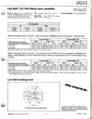
Jib Capacities<br />
Lattice Boom Crawler Crane<br />
<strong>138</strong> <strong>HYLAB</strong> 5 <strong>80–ton</strong> (72.6 metric ton)<br />
Angle Boom + Jib<br />
� 40’–140’ (12.19 – 42.7m) Angle Boom with<br />
30’ – 60’ (9.14 – 18.28m) of Jib<br />
� 40’ – 150’ (12.19 – 45.72m) Angle Boom with<br />
30’ (9.14m) of Jib<br />
� 20’ (6.10m) Open Throat Top Section with<br />
32” (0.81m) Wide x 24” (0.61m) Deep Jib<br />
� �������������������������������������<br />
� Extended / Retracted Side Frames<br />
� Over End Blocked Capacities<br />
� 360� Capacities<br />
� “AB” Counterweight Options<br />
� 20’ 2” (6.15m) Crawler Length<br />
CAUTION: This material is supplied for reference use only. Operator must refer to<br />
in–cab Crane Rating Manual to determine allowable crane lifting capacities and<br />
operating procedures.
TUBULAR JIB NOTES FOR OPEN THROAT BOOM<br />
1. Capacities are for a <strong>138</strong> <strong>HYLAB</strong> crawler crane with AB (50,500 lb) counterweight.<br />
2. Separate capacity charts are listed for 360� and for over end blocked crawler working areas. Verify operating<br />
conditions as described on the Working Area Chart found in the general information section of the Crane Rating<br />
Manual. Apply the appropriate lift capacity chart based on the working area and the specific operating<br />
conditions.<br />
3. Over end blocked capacities can be lifted over either end with the crane standing level on a firm supporting<br />
surface. Adequate blocking must be placed under both side frame sprockets (or idler rollers) at the end that the<br />
load is to be lifted to prevent rocking. The ramps supplied with the crane are considered to be adequate<br />
blocking.<br />
4. Capacities are for side frames in the extended position only and are based on the crane standing level on a firm<br />
supporting surface.<br />
5. Capacities are limited to a LBCE 48” x 48” angle boom with an open throat and a LBCE 12 ton, 24” x 32”<br />
cross section jib with a 11’6” high jib mast properly assembled.<br />
6. Two parts of 7/8” Diameter Type “DB” or Type “RB” wire rope are required for maximum lift.<br />
7. Capacities are for 30’, 45’, and 60’ jib lengths only.<br />
8. Maximum boom plus jib combination is 140’ + 60’ or 150’ + 30’. The only jib length available on the 150’ open<br />
throat boom length is 30’.<br />
9. The least stable condition is over the side.<br />
10. All capacities are listed in pounds and are not more than 75% of the tipping loads. Those capacities followed by<br />
an asterisk (*) are governed by factors other than those that would cause a tipping condition.<br />
11. A deduction must be made from the jib capacities for the weight of the following: Main boom hook block or hook<br />
ball, jib hook block or hook ball, slings, grapple, load weighing devices (other than those supplied with the<br />
crane), etc.<br />
B<br />
������������������������������<br />
A<br />
25�<br />
15�<br />
5�<br />
��������������������������������
Height in feet above ground<br />
220’<br />
210’<br />
200’<br />
190’<br />
180’<br />
170’<br />
160’<br />
150’<br />
140’<br />
130’<br />
120’<br />
110’<br />
100’<br />
90’<br />
80’<br />
70’<br />
60’<br />
50’<br />
40’<br />
30’<br />
20’<br />
10’<br />
0’<br />
200’<br />
20�<br />
30�<br />
180’<br />
40�<br />
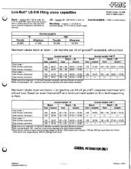
Minimum Boom Angle<br />
See Note 2.<br />
WORKING RANGE DIAGRAM<br />
�����������������������������������������<br />
160’<br />
50�<br />
60�<br />
140’ 120’ 100’ 80’ 60’<br />
Operating radius from centerline of rotation.<br />
Maximum Boom Angle<br />
See Note 2.<br />
������<br />
�� ��������������������������������������������������������������������������������������������������������������������<br />
������������������������������������������������������������������������������������������<br />
�� ����������������������������������������������������������������������������������������������������������<br />
25�<br />
70�<br />
15�<br />
5�<br />
80�<br />
40’<br />
20’<br />
60’<br />
45’<br />
30’<br />
140’<br />
130’<br />
120’<br />
110’<br />
100’<br />
90’<br />
80’<br />
70’<br />
60’<br />
50’<br />
40’<br />
OF<br />
CL<br />
ROTATION<br />
Jib Length<br />
Main Boom Length
Height in feet above ground<br />
220’<br />
210’<br />
200’<br />
190’<br />
180’<br />
170’<br />
160’<br />
150’<br />
140’<br />
130’<br />
120’<br />
110’<br />
100’<br />
90’<br />
80’<br />
70’<br />
60’<br />
50’<br />
40’<br />
30’<br />
20’<br />
10’<br />
0’<br />
200’<br />
20�<br />
30�<br />
180’<br />
40�<br />
Minimum Boom Angle<br />
See Note 2.<br />
WORKING RANGE DIAGRAM<br />
160’<br />
����������������������������������<br />
50�<br />
140’<br />
120’<br />
60�<br />
100’<br />
������<br />
�� ��������������������������������������������������������������������������������������������������������������������<br />
������������������������������������������������������������������������������������������<br />
�� ����������������������������������������������������������������������������������������������������������<br />
80’<br />
Operating radius from centerline of rotation.<br />
5�<br />
70� 15� 80�<br />
25�<br />
60’<br />
Maximum Boom Angle<br />
See Note 2.<br />
40’<br />
20’<br />
10’<br />
30’<br />
150’<br />
140’<br />
130’<br />
120’<br />
110’<br />
100’<br />
90’<br />
80’<br />
70’<br />
60’<br />
50’<br />
40’<br />
0’<br />
OF<br />
CL<br />
ROTATION<br />
Jib Length<br />
Main Boom Length
Boom<br />
Length<br />
(ft)<br />
Jib<br />
Length<br />
(ft)<br />
Jib<br />
Load<br />
Radius<br />
(ft)<br />
<strong>138</strong> <strong>HYLAB</strong> 5 - w/ 48" x 48" Angle Boom, w/ 24" x 32" Tube Jib, w/ "AB" Ctwt<br />
Refer to the Tubular Jib notes for Open Throat Boom in the Crane Rating Manual before operating the crane.<br />
Boom<br />
Angle<br />
(deg)<br />
Jib Point<br />
Height<br />
(ft)<br />
5 Degrees<br />
Jib Angle to Boom<br />
15 Degrees 25 Degrees<br />
Over End Jib<br />
Capacity (lbs)<br />
360°<br />
Jib Capacity<br />
(lbs)<br />
Boom<br />
Angle<br />
(deg)<br />
Jib Point<br />
Height<br />
(ft)<br />
Over End Jib<br />
Capacity (lbs)<br />
360°<br />
Jib Capacity<br />
(lbs)<br />
40 30 18.4 80.0 76.0 24,000 * 24,000 * 18.4<br />
40 30 19 79.4 75.9 24,000 * 24,000 * 19<br />
40 30 20 78.6 75.6 24,000 * 24,000 * 20<br />
40 30 25 74.5 74.2 24,000 * 24,000 * 78.5 73.8 24,000 * 24,000 * 25<br />
40 30 30 70.2 72.4 24,000 * 24,000 * 74.2 72.0 24,000 * 24,000 * 78.0 70.8 19,700 * 19,700 * 30<br />
40 30 35 65.9 70.2 24,000 * 24,000 * 69.8 69.8 23,600 * 23,600 * 73.5 68.5 17,700 * 17,700 * 35<br />
40 30 40 61.3 67.5 24,000 * 24,000 * 65.2 67.1 21,000 * 21,000 * 68.9 65.7 16,900 * 16,900 * 40<br />
40 30 50 51.5 60.3 20,900 * 20,900 * 55.3 59.8 17,300 * 17,300 * 58.7 58.3 14,700 * 14,700 * 50<br />
40 30 60 39.9 49.8 17,300 * 17,300 * 43.5 49.2 16,200 * 16,200 * 46.5 47.2 13,200 * 13,200 * 60<br />
40 45 22.2 80.0 90.2 24,000 * 24,000 * 22.2<br />
40 45 25 78.1 89.5 24,000 * 24,000 * 25<br />
40 45 30 74.7 88.0 24,000 * 24,000 * 79.7 87.4 19,200 * 19,200 * 30<br />
40 45 35 71.2 86.2 21,700 * 21,700 * 76.2 85.6 17,300 * 17,300 * 35<br />
40 45 40 67.6 84.0 19,000 * 19,000 * 72.5 83.4 16,600 * 16,600 * 77.3 81.7 12,500 * 12,500 * 40<br />
40 45 50 60.0 78.3 16,600 * 16,600 * 64.9 77.8 13,500 * 13,500 * 69.5 75.9 10,500 * 10,500 * 50<br />
40 45 60 51.8 70.8 13,700 * 13,700 * 56.6 70.2 11,400 * 11,400 * 61.0 68.1 9,200 * 9,200 * 60<br />
40 45 70 42.3 60.5 11,600 * 11,600 * 47.0 59.8 10,000 * 10,000 * 51.1 57.3 8,200 * 8,200 * 70<br />
40 45 80 30.4 45.4 10,100 * 10,100 * 80<br />
40 60 26.1 80.0 104.8 24,000 * 24,000 * 26.1<br />
40 60 30 77.7 103.8 21,200 * 21,200 * 30<br />
40 60 35 74.8 102.2 18,200 * 18,200 * 35<br />
40 60 40 71.8 100.4 17,300 * 17,300 * 77.5 99.8 13,700 * 13,700 * 40<br />
40 60 50 65.6 95.9 13,700 * 13,700 * 71.3 95.3 11,100 * 11,100 * 76.8 93.3 8,500 * 8,500 * 50<br />
40 60 60 59.1 89.9 11,300 * 11,300 * 64.7 89.3 9,300 * 9,300 * 70.0 87.1 7,300 * 7,300 * 60<br />
40 60 70 52.0 82.1 9,500 * 9,500 * 57.5 81.5 8,000 * 8,000 * 62.7 79.2 6,400 * 6,400 * 70<br />
40 60 80 44.0 72.1 8,200 * 8,200 * 49.4 71.4 7,100 * 7,100 * 54.3 68.7 5,800 * 5,800 * 80<br />
40 60 90 34.5 58.4 7,300 * 7,300 * 39.7 57.5 6,300 * 6,300 * 90<br />
Boom<br />
Angle<br />
(deg)<br />
Jib Point<br />
Height<br />
(ft)<br />
Over End Jib<br />
Capacity (lbs)<br />
360°<br />
Jib Capacity<br />
(lbs)<br />
Jib<br />
Load<br />
Radius<br />
(ft)
Boom<br />
Length<br />
(ft)<br />
Jib<br />
Length<br />
(ft)<br />
Jib<br />
Load<br />
Radius<br />
(ft)<br />
<strong>138</strong> <strong>HYLAB</strong> 5 - w/ 48" x 48" Angle Boom, w/ 24" x 32" Tube Jib, w/ "AB" Ctwt<br />
Refer to the Tubular Jib notes for Open Throat Boom in the Crane Rating Manual before operating the crane.<br />
Boom<br />
Angle<br />
(deg)<br />
Jib Point<br />
Height<br />
(ft)<br />
5 Degrees<br />
Jib Angle to Boom<br />
15 Degrees 25 Degrees<br />
Over End Jib<br />
Capacity (lbs)<br />
360°<br />
Jib Capacity<br />
(lbs)<br />
Boom<br />
Angle<br />
(deg)<br />
Jib Point<br />
Height<br />
(ft)<br />
Over End Jib<br />
Capacity (lbs)<br />
360°<br />
Jib Capacity<br />
(lbs)<br />
Boom<br />
Angle<br />
(deg)<br />
Jib Point<br />
Height<br />
(ft)<br />
Over End Jib<br />
Capacity (lbs)<br />
360°<br />
Jib Capacity<br />
(lbs)<br />
50 30 20.1 80.0 85.9 24,000 * 24,000 * 20.1<br />
50 30 25 76.4 84.7 24,000 * 24,000 * 25<br />
50 30 30 72.8 83.1 24,000 * 24,000 * 76.3 82.6 24,000 * 24,000 * 79.6 81.3 20,500 * 20,500 * 30<br />
50 30 35 69.0 81.2 24,000 * 24,000 * 72.5 80.7 24,000 * 24,000 * 75.8 79.4 18,600 * 18,600 * 35<br />
50 30 40 65.2 78.9 24,000 * 24,000 * 68.6 78.4 22,800 * 22,800 * 71.8 77.0 17,400 * 17,400 * 40<br />
50 30 50 57.0 72.9 23,600 * 23,600 * 60.4 72.4 18,900 * 18,900 * 63.4 70.9 15,600 * 15,600 * 50<br />
50 30 60 47.9 64.7 19,500 * 19,500 * 51.2 64.2 17,400 * 17,400 * 54.0 62.4 14,000 * 14,000 * 60<br />
50 30 70 37.2 53.1 17,400 * 16,700 40.2 52.4 15,600 * 15,700 * 70<br />
50 45 24.0 80.0 100.1 24,000 * 24,000 * 24.0<br />
50 45 25 79.4 99.8 24,000 * 24,000 * 25<br />
50 45 30 76.3 98.5 24,000 * 24,000 * 30<br />
50 45 35 73.2 96.8 23,500 * 23,500 * 77.7 96.2 17,700 * 17,700 * 35<br />
50 45 40 70.0 94.9 20,700 * 20,700 * 74.5 94.2 17,300 * 17,300 * 78.8 92.4 13,000 * 13,000 * 40<br />
50 45 50 63.5 90.0 17,300 * 17,300 * 67.9 89.4 14,500 * 14,500 * 72.0 87.4 11,100 * 11,100 * 50<br />
50 45 60 56.4 83.6 15,100 * 15,100 * 60.8 82.9 12,400 * 12,400 * 64.8 80.8 9,700 * 9,700 * 60<br />
50 45 70 48.7 75.2 12,900 * 12,900 * 53.0 74.4 10,800 * 10,800 * 56.7 72.0 8,700 * 8,700 * 70<br />
50 45 80 39.9 64.0 11,200 * 11,200 * 43.9 63.1 9,600 * 9,600 * 47.4 60.3 7,900 * 7,900 * 80<br />
50 45 90 28.7 47.8 10,000 * 10,000 * 90<br />
50 60 27.9 80.0 114.6 24,000 * 24,000 * 27.9<br />
50 60 30 78.8 114.1 22,600 * 22,600 * 30<br />
50 60 35 76.2 112.7 19,500 * 19,500 * 35<br />
50 60 40 73.5 111.1 17,300 * 17,300 * 78.7 110.4 14,400 * 14,400 * 40<br />
50 60 50 68.0 107.0 14,900 * 14,900 * 73.1 106.3 11,800 * 11,800 * 78.1 104.2 8,800 * 8,800 * 50<br />
50 60 60 62.2 101.7 12,300 * 12,300 * 67.3 101.0 9,900 * 9,900 * 72.1 98.7 7,600 * 7,600 * 60<br />
50 60 70 56.0 95.0 10,400 * 10,400 * 61.1 94.3 8,600 * 8,600 * 65.8 91.8 6,700 * 6,700 * 70<br />
50 60 80 49.3 86.5 9,000 * 9,000 * 54.3 85.8 7,600 * 7,600 * 58.8 83.0 6,100 * 6,100 * 80<br />
50 60 90 41.8 75.7 7,900 * 7,900 * 46.6 74.8 6,800 * 6,800 * 50.9 71.6 5,500 * 5,500 * 90<br />
50 60 100 32.7 61.1 7,100 * 7,100 * 37.3 59.9 6,200 * 6,200 * 100<br />
Jib<br />
Load<br />
Radius<br />
(ft)
Boom<br />
Length<br />
(ft)<br />
Jib<br />
Length<br />
(ft)<br />
Jib<br />
Load<br />
Radius<br />
(ft)<br />
<strong>138</strong> <strong>HYLAB</strong> 5 - w/ 48" x 48" Angle Boom, w/ 24" x 32" Tube Jib, w/ "AB" Ctwt<br />
Refer to the Tubular Jib notes for Open Throat Boom in the Crane Rating Manual before operating the crane.<br />
Boom<br />
Angle<br />
(deg)<br />
Jib Point<br />
Height<br />
(ft)<br />
5 Degrees<br />
Jib Angle to Boom<br />
15 Degrees 25 Degrees<br />
Over End Jib<br />
Capacity (lbs)<br />
360°<br />
Jib Capacity<br />
(lbs)<br />
Boom<br />
Angle<br />
(deg)<br />
Jib Point<br />
Height<br />
(ft)<br />
Over End Jib<br />
Capacity (lbs)<br />
360°<br />
Jib Capacity<br />
(lbs)<br />
Boom<br />
Angle<br />
(deg)<br />
Jib Point<br />
Height<br />
(ft)<br />
Over End Jib<br />
Capacity (lbs)<br />
360°<br />
Jib Capacity<br />
(lbs)<br />
60 30 21.8 80.0 95.7 24,000 * 24,000 * 21.8<br />
60 30 25 77.9 95.0 24,000 * 24,000 * 25<br />
60 30 30 74.7 93.6 24,000 * 24,000 * 77.8 93.1 24,000 * 24,000 * 30<br />
60 30 35 71.4 91.9 24,000 * 24,000 * 74.5 91.4 24,000 * 24,000 * 77.5 90.0 19,400 * 19,400 * 35<br />
60 30 40 68.1 89.9 24,000 * 24,000 * 71.1 89.4 24,000 * 24,000 * 74.0 88.0 17,900 * 17,900 * 40<br />
60 30 50 61.0 84.8 24,000 * 24,000 * 64.1 84.3 20,400 * 20,400 * 66.8 82.7 16,300 * 16,300 * 50<br />
60 30 60 53.5 78.0 21,700 * 20,100 56.4 77.4 17,600 * 17,600 * 59.0 75.7 14,700 * 14,700 * 60<br />
60 30 70 45.0 68.8 18,600 * 16,400 47.8 68.2 17,100 * 16,600 50.2 66.2 13,500 * 13,500 * 70<br />
60 30 80 34.9 56.2 16,000 * 13,700 37.6 55.3 15,300 * 13,800 80<br />
60 45 25.7 80.0 109.9 24,000 * 24,000 * 25.7<br />
60 45 30 77.6 108.9 24,000 * 24,000 * 30<br />
60 45 35 74.8 107.4 24,000 * 24,000 * 78.9 106.7 18,500 * 18,500 * 35<br />
60 45 40 72.0 105.7 22,400 * 22,400 * 76.0 104.9 17,300 * 17,300 * 79.9 103.0 13,300 * 13,300 * 40<br />
60 45 50 66.2 101.3 18,000 * 18,000 * 70.2 100.6 15,400 * 15,400 * 73.9 98.5 11,500 * 11,500 * 50<br />
60 45 60 60.0 95.7 16,600 * 16,600 * 63.9 94.9 13,200 * 13,200 * 67.6 92.8 10,100 * 10,100 * 60<br />
60 45 70 53.4 88.5 14,100 * 14,100 * 57.3 87.7 11,600 * 11,600 * 60.8 85.3 9,100 * 9,100 * 70<br />
60 45 80 46.2 79.3 12,300 * 12,300 * 49.9 78.4 10,300 * 10,300 * 53.2 75.8 8,300 * 8,300 * 80<br />
60 45 90 37.8 67.2 10,900 * 10,900 * 41.4 66.2 9,400 * 9,400 * 90<br />
60 45 100 27.2 50.1 9,900 * 9,900 * 100<br />
60 60 29.6 80.0 124.5 24,000 * 24,000 * 29.6<br />
60 60 30 79.8 124.4 23,900 * 23,900 * 30<br />
60 60 35 77.4 123.1 20,700 * 20,700 * 35<br />
60 60 40 74.9 121.6 18,200 * 18,200 * 79.7 120.8 14,900 * 14,900 * 40<br />
60 60 50 69.9 117.9 16,100 * 16,100 * 74.6 117.1 12,300 * 12,300 * 79.2 114.9 9,100 * 9,100 * 50<br />
60 60 60 64.7 113.2 13,300 * 13,300 * 69.4 112.4 10,500 * 10,500 * 73.8 110.0 7,900 * 7,900 * 60<br />
60 60 70 59.2 107.2 11,300 * 11,300 * 63.9 106.4 9,100 * 9,100 * 68.2 103.9 7,000 * 7,000 * 70<br />
60 60 80 53.4 99.8 9,800 * 9,800 * 58.0 99.0 8,100 * 8,100 * 62.2 96.2 6,300 * 6,300 * 80<br />
60 60 90 47.0 90.7 8,600 * 8,600 * 51.5 89.8 7,200 * 7,200 * 55.5 86.7 5,800 * 5,800 * 90<br />
60 60 100 39.9 79.1 7,700 * 7,700 * 44.2 78.1 6,600 * 6,600 * 47.9 74.5 5,400 * 5,400 * 100<br />
60 60 110 31.2 63.7 7,000 * 7,000 * 35.3 62.3 6,100 * 6,100 * 110<br />
Jib<br />
Load<br />
Radius<br />
(ft)
Boom<br />
Length<br />
(ft)<br />
Jib<br />
Length<br />
(ft)<br />
Jib<br />
Load<br />
Radius<br />
(ft)<br />
<strong>138</strong> <strong>HYLAB</strong> 5 - w/ 48" x 48" Angle Boom, w/ 24" x 32" Tube Jib, w/ "AB" Ctwt<br />
Refer to the Tubular Jib notes for Open Throat Boom in the Crane Rating Manual before operating the crane.<br />
Boom<br />
Angle<br />
(deg)<br />
Jib Point<br />
Height<br />
(ft)<br />
5 Degrees<br />
Jib Angle to Boom<br />
15 Degrees 25 Degrees<br />
Over End Jib<br />
Capacity (lbs)<br />
360°<br />
Jib Capacity<br />
(lbs)<br />
Boom<br />
Angle<br />
(deg)<br />
Jib Point<br />
Height<br />
(ft)<br />
Over End Jib<br />
Capacity (lbs)<br />
360°<br />
Jib Capacity<br />
(lbs)<br />
Boom<br />
Angle<br />
(deg)<br />
Jib Point<br />
Height<br />
(ft)<br />
Over End Jib<br />
Capacity (lbs)<br />
360°<br />
Jib Capacity<br />
(lbs)<br />
70 30 23.6 80.0 105.6 24,000 * 24,000 * 23.6<br />
70 30 25 79.2 105.2 24,000 * 24,000 * 25<br />
70 30 30 76.3 104.0 24,000 * 24,000 * 79.1 103.5 24,000 * 24,000 * 30<br />
70 30 35 73.3 102.5 24,000 * 24,000 * 76.1 102.0 24,000 * 24,000 * 78.8 100.5 20,000 * 20,000 * 35<br />
70 30 40 70.3 100.7 24,000 * 24,000 * 73.1 100.2 24,000 * 24,000 * 75.7 98.7 18,500 * 18,500 * 40<br />
70 30 50 64.1 96.2 24,000 * 24,000 * 66.9 95.7 21,800 * 21,800 * 69.4 94.1 17,000 * 17,000 * 50<br />
70 30 60 57.6 90.3 23,000 * 19,900 60.3 89.7 18,800 * 18,800 * 62.7 88.0 15,400 * 15,400 * 60<br />
70 30 70 50.5 82.7 19,000 16,200 53.1 82.0 17,300 * 16,400 55.4 80.2 14,200 * 14,200 * 70<br />
70 30 80 42.6 72.7 15,900 13,400 45.1 72.0 16,000 13,600 47.1 69.8 13,200 * 13,200 * 80<br />
70 30 90 33.0 59.1 13,100 * 11,300 35.4 58.1 13,500 11,400 90<br />
70 45 27.5 80.0 119.8 24,000 * 24,000 * 27.5<br />
70 45 30 78.7 119.2 24,000 * 24,000 * 30<br />
70 45 35 76.2 117.8 24,000 * 24,000 * 79.9 117.0 19,200 * 19,200 * 35<br />
70 45 40 73.6 116.3 23,900 * 23,900 * 77.3 115.5 17,400 * 17,400 * 40<br />
70 45 50 68.3 112.3 19,400 * 19,400 * 72.0 111.6 16,300 * 16,300 * 75.4 109.5 11,900 * 11,900 * 50<br />
70 45 60 62.9 107.3 17,300 * 17,300 * 66.5 106.5 14,000 * 14,000 * 69.8 104.3 10,600 * 10,600 * 60<br />
70 45 70 57.1 101.0 15,300 * 15,400 * 60.6 100.2 12,300 * 12,300 * 63.8 97.8 9,500 * 9,500 * 70<br />
70 45 80 50.8 93.1 13,400 * 13,400 * 54.3 92.2 11,000 * 11,000 * 57.4 89.7 8,700 * 8,700 * 80<br />
70 45 90 44.0 83.2 11,900 * 11,600 47.3 82.2 10,000 * 10,000 * 50.2 79.3 8,100 * 8,100 * 90<br />
70 45 100 36.0 70.3 10,700 * 9,900 39.2 69.2 9,200 * 9,200 * 100<br />
70 60 31.3 80.0 134.3 24,000 * 24,000 * 31.3<br />
70 60 35 78.3 133.5 21,800 * 21,800 * 35<br />
70 60 40 76.1 132.1 19,300 * 19,300 * 40<br />
70 60 50 71.5 128.7 17,200 * 17,200 * 75.9 127.8 12,900 * 12,900 * 50<br />
70 60 60 66.8 124.4 14,300 * 14,300 * 71.1 123.5 11,000 * 11,000 * 75.2 121.0 8,200 * 8,200 * 60<br />
70 60 70 61.8 119.0 12,100 * 12,100 * 66.1 118.1 9,600 * 9,600 * 70.1 115.5 7,300 * 7,300 * 70<br />
70 60 80 56.7 112.4 10,500 * 10,600 * 60.9 111.6 8,500 * 8,500 * 64.8 108.7 6,600 * 6,600 * 80<br />
70 60 90 51.1 104.5 9,300 * 9,300 * 55.3 103.5 7,700 * 7,700 * 59.0 100.5 6,100 * 6,100 * 90<br />
70 60 100 45.0 94.7 8,300 * 8,300 * 49.1 93.6 7,000 * 7,000 * 52.7 90.3 5,600 * 5,600 * 100<br />
70 60 110 38.2 82.4 7,500 * 7,500 * 42.1 81.2 6,400 * 6,400 * 110<br />
70 60 120 29.9 66.2 6,900 * 6,900 * 120<br />
Jib<br />
Load<br />
Radius<br />
(ft)
Boom<br />
Length<br />
(ft)<br />
Jib<br />
Length<br />
(ft)<br />
Jib<br />
Load<br />
Radius<br />
(ft)<br />
<strong>138</strong> <strong>HYLAB</strong> 5 - w/ 48" x 48" Angle Boom, w/ 24" x 32" Tube Jib, w/ "AB" Ctwt<br />
Refer to the Tubular Jib notes for Open Throat Boom in the Crane Rating Manual before operating the crane.<br />
Boom<br />
Angle<br />
(deg)<br />
Jib Point<br />
Height<br />
(ft)<br />
5 Degrees<br />
Jib Angle to Boom<br />
15 Degrees 25 Degrees<br />
Over End Jib<br />
Capacity (lbs)<br />
360°<br />
Jib Capacity<br />
(lbs)<br />
Boom<br />
Angle<br />
(deg)<br />
Jib Point<br />
Height<br />
(ft)<br />
Over End Jib<br />
Capacity (lbs)<br />
360°<br />
Jib Capacity<br />
(lbs)<br />
Boom<br />
Angle<br />
(deg)<br />
Jib Point<br />
Height<br />
(ft)<br />
Over End Jib<br />
Capacity (lbs)<br />
360°<br />
Jib Capacity<br />
(lbs)<br />
80 30 25.3 80.0 115.4 24,000 * 24,000 * 25.3<br />
80 30 30 77.5 114.3 24,000 * 24,000 * 0 30<br />
80 30 35 74.9 113.0 24,000 * 24,000 * 77.4 112.4 24,000 * 24,000 * 79.8 110.9 20,600 * 20,600 * 35<br />
80 30 40 72.2 111.4 24,000 * 24,000 * 74.7 110.8 24,000 * 24,000 * 77.1 109.3 19,100 * 19,100 * 40<br />
80 30 50 66.6 107.4 24,000 * 24,000 * 69.1 106.8 23,100 * 23,100 * 71.4 105.2 17,300 * 17,300 * 50<br />
80 30 60 60.8 102.1 23,200 19,600 63.3 101.5 20,000 * 19,900 65.5 99.8 16,000 * 16,000 * 60<br />
80 30 70 54.7 95.5 18,800 15,900 57.1 94.9 17,700 * 16,200 59.2 93.0 14,700 * 14,700 * 70<br />
80 30 80 48.0 87.1 15,600 13,200 50.3 86.4 15,800 13,300 52.3 84.4 13,700 * 13,500 80<br />
80 30 90 40.5 76.3 13,200 11,100 42.7 75.5 13,300 11,200 90<br />
80 30 100 31.4 61.8 10,700 * 9,400 100<br />
80 45 29.2 80.0 129.6 24,000 * 24,000 * 29.2<br />
80 45 30 79.6 129.4 24,000 * 24,000 * 30<br />
80 45 35 77.3 128.2 24,000 * 24,000 * 35<br />
80 45 40 74.9 126.8 24,000 * 24,000 * 78.3 125.9 18,100 * 18,100 * 40<br />
80 45 50 70.1 123.2 20,700 * 20,700 * 73.5 122.4 17,100 * 17,100 * 76.7 120.2 12,200 * 12,200 * 50<br />
80 45 60 65.2 118.6 17,400 * 17,400 * 68.5 117.8 14,700 * 14,700 * 71.6 115.6 10,900 * 10,900 * 60<br />
80 45 70 60.0 113.0 16,500 * 16,200 63.3 112.1 13,000 * 13,000 * 66.3 109.8 9,900 * 9,900 * 70<br />
80 45 80 54.5 106.0 14,400 * 13,400 57.8 105.2 11,600 * 11,600 * 60.6 102.6 9,100 * 9,100 * 80<br />
80 45 90 48.6 97.5 12,800 * 11,300 51.8 96.6 10,600 * 10,600 * 54.5 93.8 8,400 * 8,400 * 90<br />
80 45 100 42.0 86.9 11,500 * 9,700 45.1 85.8 9,700 * 9,700 * 47.6 82.7 7,900 * 7,900 * 100<br />
80 45 110 34.4 73.3 9,800 * 8,300 37.3 72.0 9,000 * 8,400 110<br />
80 60 33.1 80.0 144.2 23,700 * 23,700 * 33.1<br />
80 60 35 79.2 143.7 22,800 * 22,800 * 35<br />
80 60 40 77.1 142.5 20,300 * 20,300 * 40<br />
80 60 50 72.9 139.3 17,300 * 17,300 * 76.9 <strong>138</strong>.4 13,400 * 13,400 * 50<br />
80 60 60 68.5 135.4 15,200 * 15,200 * 72.6 134.5 11,500 * 11,500 * 76.4 131.9 8,400 * 8,400 * 60<br />
80 60 70 64.0 130.5 13,000 * 13,000 * 68.0 129.6 10,100 * 10,100 * 71.8 126.8 7,500 * 7,500 * 70<br />
80 60 80 59.3 124.5 11,300 * 11,300 * 63.3 123.6 9,000 * 9,000 * 66.9 120.7 6,800 * 6,900 * 80<br />
80 60 90 54.4 117.4 10,000 * 10,000 * 58.3 116.5 8,100 * 8,100 * 61.8 113.4 6,300 * 6,300 * 90<br />
80 60 100 49.1 108.9 8,900 * 8,900 * 52.9 107.8 7,400 * 7,400 * 56.3 104.5 5,800 * 5,800 * 100<br />
Jib<br />
Load<br />
Radius<br />
(ft)
Boom<br />
Length<br />
(ft)<br />
Jib<br />
Length<br />
(ft)<br />
Jib<br />
Load<br />
Radius<br />
(ft)<br />
<strong>138</strong> <strong>HYLAB</strong> 5 - w/ 48" x 48" Angle Boom, w/ 24" x 32" Tube Jib, w/ "AB" Ctwt<br />
Refer to the Tubular Jib notes for Open Throat Boom in the Crane Rating Manual before operating the crane.<br />
Boom<br />
Angle<br />
(deg)<br />
Jib Point<br />
Height<br />
(ft)<br />
5 Degrees<br />
Jib Angle to Boom<br />
15 Degrees 25 Degrees<br />
Over End Jib<br />
Capacity (lbs)<br />
360°<br />
Jib Capacity<br />
(lbs)<br />
Boom<br />
Angle<br />
(deg)<br />
Jib Point<br />
Height<br />
(ft)<br />
Over End Jib<br />
Capacity (lbs)<br />
360°<br />
Jib Capacity<br />
(lbs)<br />
Boom<br />
Angle<br />
(deg)<br />
Jib Point<br />
Height<br />
(ft)<br />
Over End Jib<br />
Capacity (lbs)<br />
360°<br />
Jib Capacity<br />
(lbs)<br />
80 60 110 43.3 98.5 8,100 * 8,100 * 47.0 97.3 6,800 * 6,800 * 50.2 93.6 5,500 * 5,500 * 110<br />
80 60 120 36.7 85.6 7,400 * 7,400 * 40.3 84.2 6,300 * 6,300 * 120<br />
80 60 130 28.7 68.6 6,800 * 6,400 130<br />
90 30 27.0 80.0 125.3 24,000 * 24,000 * 27.0<br />
90 30 30 78.6 124.6 24,000 * 24,000 * 30<br />
90 30 35 76.1 123.4 24,000 * 24,000 * 78.5 122.8 24,000 * 24,000 * 35<br />
90 30 40 73.7 121.9 24,000 * 24,000 * 76.0 121.3 24,000 * 24,000 * 78.2 119.8 19,700 * 19,700 * 40<br />
90 30 50 68.7 118.3 24,000 * 24,000 * 71.0 117.7 23,900 * 23,800 * 73.1 116.1 17,400 * 17,400 * 50<br />
90 30 60 63.5 113.6 23,000 19,400 65.7 113.0 21,100 * 19,700 67.8 111.3 16,500 * 16,500 * 60<br />
90 30 70 58.0 107.7 18,500 15,700 60.2 107.1 18,700 15,900 62.2 105.3 15,300 * 15,300 * 70<br />
90 30 80 52.2 100.4 15,400 12,900 54.4 99.7 15,600 13,100 56.2 97.8 14,200 * 13,300 80<br />
90 30 90 45.8 91.3 12,900 10,800 47.9 90.6 13,100 11,000 49.7 88.4 13,200 11,100 90<br />
90 30 100 38.6 79.8 11,000 9,200 40.7 78.9 11,100 9,300 100<br />
90 30 110 30.0 64.5 8,700 * 7,800 110<br />
90 45 30.9 80.0 139.5 24,000 * 24,000 * 30.9<br />
90 45 35 78.2 <strong>138</strong>.5 24,000 * 24,000 * 35<br />
90 45 40 76.1 137.2 24,000 * 24,000 * 79.2 136.3 18,700 * 18,700 * 40<br />
90 45 50 71.7 133.9 21,000 * 21,000 * 74.8 133.1 17,300 * 17,300 * 77.8 130.8 12,600 * 12,600 * 50<br />
90 45 60 67.1 129.8 18,300 * 18,300 * 70.2 128.9 15,400 * 15,400 * 73.1 126.6 11,300 * 11,300 * 60<br />
90 45 70 62.4 124.6 16,800 * 16,000 65.5 123.7 13,600 * 13,600 * 68.3 121.3 10,200 * 10,200 * 70<br />
90 45 80 57.5 118.4 15,000 * 13,200 60.5 117.5 12,200 * 12,200 * 63.2 114.9 9,400 * 9,400 * 80<br />
90 45 90 52.3 110.8 13,200 11,100 55.2 109.9 11,100 * 11,100 * 57.8 107.2 8,700 * 8,700 * 90<br />
90 45 100 46.6 101.7 11,300 9,400 49.5 100.7 10,200 * 9,600 52.0 97.7 8,200 * 8,200 * 100<br />
90 45 110 40.3 90.5 9,700 8,000 43.1 89.3 9,500 * 8,200 110<br />
90 45 120 33.0 76.2 8,000 * 6,900 120<br />
90 60 34.8 80.0 154.0 22,800 * 22,800 * 34.8<br />
90 60 35 79.9 154.0 22,700 * 22,700 * 35<br />
90 60 40 78.0 152.8 20,800 * 20,800 * 40<br />
90 60 50 74.0 149.9 17,400 * 17,400 * 77.8 148.9 13,800 * 13,800 * 50<br />
90 60 60 70.0 146.2 16,100 * 16,000 * 73.8 145.3 11,900 * 12,000 * 77.4 142.6 8,600 * 8,600 * 60<br />
Jib<br />
Load<br />
Radius<br />
(ft)
Boom<br />
Length<br />
(ft)<br />
Jib<br />
Length<br />
(ft)<br />
Jib<br />
Load<br />
Radius<br />
(ft)<br />
<strong>138</strong> <strong>HYLAB</strong> 5 - w/ 48" x 48" Angle Boom, w/ 24" x 32" Tube Jib, w/ "AB" Ctwt<br />
Refer to the Tubular Jib notes for Open Throat Boom in the Crane Rating Manual before operating the crane.<br />
Boom<br />
Angle<br />
(deg)<br />
Jib Point<br />
Height<br />
(ft)<br />
5 Degrees<br />
Jib Angle to Boom<br />
15 Degrees 25 Degrees<br />
Over End Jib<br />
Capacity (lbs)<br />
360°<br />
Jib Capacity<br />
(lbs)<br />
Boom<br />
Angle<br />
(deg)<br />
Jib Point<br />
Height<br />
(ft)<br />
Over End Jib<br />
Capacity (lbs)<br />
360°<br />
Jib Capacity<br />
(lbs)<br />
Boom<br />
Angle<br />
(deg)<br />
Jib Point<br />
Height<br />
(ft)<br />
Over End Jib<br />
Capacity (lbs)<br />
360°<br />
Jib Capacity<br />
(lbs)<br />
90 60 70 65.9 141.7 13,800 * 13,800 * 69.6 140.7 10,500 * 10,500 * 73.1 <strong>138</strong>.0 7,700 * 7,700 * 70<br />
90 60 80 61.6 136.3 12,000 * 12,000 * 65.3 135.3 9,400 * 9,400 * 68.7 132.4 7,100 * 7,100 * 80<br />
90 60 90 57.1 129.9 10,600 * 10,600 * 60.8 128.8 8,500 * 8,500 * 64.1 125.8 6,500 * 6,500 * 90<br />
90 60 100 52.4 122.2 9,500 * 9,500 * 56.0 121.1 7,700 * 7,700 * 59.2 117.9 6,000 * 6,000 * 100<br />
90 60 110 47.3 113.1 8,600 * 8,200 50.8 112.0 7,100 * 7,100 * 53.9 108.4 5,700 * 5,700 * 110<br />
90 60 120 41.7 102.2 7,900 * 7,100 45.1 100.9 6,600 * 6,600 * 48.0 96.9 5,400 * 5,400 * 120<br />
90 60 130 35.3 88.6 7,300 * 6,200 38.6 87.1 6,200 * 6,200 * 130<br />
90 60 140 27.7 70.9 5,600 * 5,400 140<br />
100 30 28.8 80.0 135.1 24,000 * 24,000 * 28.8<br />
100 30 30 79.4 134.8 24,000 * 24,000 * 30<br />
100 30 35 77.2 133.7 24,000 * 24,000 * 79.4 133.1 24,000 * 24,000 * 35<br />
100 30 40 75.0 132.4 24,000 * 24,000 * 77.1 131.8 24,000 * 24,000 * 79.2 130.2 20,100 * 20,100 * 40<br />
100 30 50 70.4 129.0 24,000 * 24,000 * 72.5 128.4 23,800 * 23,800 * 74.5 126.8 17,900 * 17,900 * 50<br />
100 30 60 65.6 124.8 22,700 19,100 67.8 124.1 21,100 * 19,500 69.7 122.5 17,000 * 17,000 * 60<br />
100 30 70 60.7 119.4 18,200 15,400 62.8 118.8 18,500 15,700 64.6 117.0 15,800 * 15,800 * 70<br />
100 30 80 55.5 112.9 15,100 12,700 57.6 112.3 15,300 12,900 59.3 110.4 14,700 * 13,100 80<br />
100 30 90 50.0 105.0 12,700 10,500 52.0 104.3 12,800 10,700 53.6 102.3 13,000 10,900 90<br />
100 30 100 43.9 95.3 10,700 8,900 45.8 94.5 10,900 9,000 47.4 92.2 11,000 9,100 100<br />
100 30 110 37.1 83.1 9,200 * 7,500 38.9 82.2 9,300 7,600 110<br />
100 30 120 28.8 67.0 7,000 * 6,400 120<br />
100 45 32.7 80.0 149.3 24,000 * 24,000 * 32.7<br />
100 45 35 79.0 148.8 24,000 * 24,000 * 35<br />
100 45 40 77.0 147.6 24,000 * 24,000 * 40<br />
100 45 50 73.0 144.5 21,100 * 21,100 * 75.9 143.6 17,300 * 17,300 * 78.7 141.4 12,800 * 12,800 * 50<br />
100 45 60 68.8 140.7 18,300 * 18,400 * 71.7 139.8 16,100 * 16,100 * 74.4 137.5 11,600 * 11,600 * 60<br />
100 45 70 64.5 136.0 16,900 * 15,700 67.3 135.1 14,300 * 14,300 * 70.0 132.7 10,500 * 10,500 * 70<br />
100 45 80 60.0 130.3 15,200 * 12,900 62.8 129.4 12,800 * 12,800 * 65.4 126.8 9,700 * 9,700 * 80<br />
100 45 90 55.3 123.5 12,900 10,800 58.1 122.6 11,700 * 11,100 60.5 119.9 9,000 * 9,000 * 90<br />
100 45 100 50.3 115.4 11,000 9,100 53.0 114.4 10,700 * 9,300 55.4 111.6 8,500 * 8,500 * 100<br />
100 45 110 44.9 105.7 9,400 7,800 47.5 104.6 9,600 8,000 49.7 101.5 8,000 * 8,000 * 110<br />
100 45 120 38.8 93.9 8,200 6,700 41.4 92.6 8,300 6,800 120<br />
100 45 130 31.8 78.9 6,500 * 5,700 130<br />
Jib<br />
Load<br />
Radius<br />
(ft)
Boom<br />
Length<br />
(ft)<br />
Jib<br />
Length<br />
(ft)<br />
Jib<br />
Load<br />
Radius<br />
(ft)<br />
<strong>138</strong> <strong>HYLAB</strong> 5 - w/ 48" x 48" Angle Boom, w/ 24" x 32" Tube Jib, w/ "AB" Ctwt<br />
Refer to the Tubular Jib notes for Open Throat Boom in the Crane Rating Manual before operating the crane.<br />
Boom<br />
Angle<br />
(deg)<br />
Jib Point<br />
Height<br />
(ft)<br />
5 Degrees<br />
Jib Angle to Boom<br />
15 Degrees 25 Degrees<br />
Over End Jib<br />
Capacity (lbs)<br />
360°<br />
Jib Capacity<br />
(lbs)<br />
Boom<br />
Angle<br />
(deg)<br />
Jib Point<br />
Height<br />
(ft)<br />
Over End Jib<br />
Capacity (lbs)<br />
360°<br />
Jib Capacity<br />
(lbs)<br />
Boom<br />
Angle<br />
(deg)<br />
Jib Point<br />
Height<br />
(ft)<br />
Over End Jib<br />
Capacity (lbs)<br />
360°<br />
Jib Capacity<br />
(lbs)<br />
100 60 36.5 80.0 163.9 22,000 * 22,000 * 36.5<br />
100 60 40 78.7 163.1 20,700 * 20,700 * 40<br />
100 60 50 75.1 160.4 17,800 * 17,800 * 78.6 159.4 14,200 * 14,200 * 50<br />
100 60 60 71.3 157.0 16,100 * 16,100 * 74.9 155.9 12,400 * 12,400 * 78.2 153.2 8,800 * 8,800 * 60<br />
100 60 70 67.5 152.8 14,300 * 14,200 * 71.0 151.8 10,900 * 10,900 * 74.3 148.9 7,900 * 7,900 * 70<br />
100 60 80 63.5 147.8 12,700 * 12,800 * 67.0 146.8 9,800 * 9,800 * 70.2 143.8 7,300 * 7,300 * 80<br />
100 60 90 59.4 141.9 11,300 * 11,000 62.9 140.8 8,900 * 8,900 * 66.0 137.8 6,700 * 6,700 * 90<br />
100 60 100 55.1 134.9 10,100 * 9,300 58.5 133.9 8,100 * 8,100 * 61.6 130.6 6,200 * 6,200 * 100<br />
100 60 110 50.6 126.8 9,200 * 7,900 53.9 125.6 7,500 * 7,500 * 56.8 122.2 5,800 * 5,800 * 110<br />
100 60 120 45.7 117.2 8,300 6,800 48.9 115.9 6,900 * 6,900 * 51.7 112.2 5,500 * 5,500 * 120<br />
100 60 130 40.3 105.7 7,300 5,900 43.4 104.3 6,500 * 6,100 46.0 100.1 5,300 * 5,300 * 130<br />
100 60 140 34.1 91.5 5,900 * 5,100 37.2 89.9 6,100 * 5,200 140<br />
100 60 150 26.7 73.1 4,400 * 4,400 * 150<br />
110 30 30.5 80.0 144.9 24,000 * 24,000 * 30.5<br />
110 30 35 78.1 144.0 24,000 * 24,000 * 35<br />
110 30 40 76.0 142.7 24,000 * 24,000 * 78.1 142.1 24,000 * 24,000 * 40<br />
110 30 50 71.8 139.7 24,000 * 24,000 * 73.8 139.0 23,700 * 23,700 * 75.7 137.4 18,400 * 18,400 * 50<br />
110 30 60 67.5 135.7 22,500 18,800 69.4 135.1 21,100 * 19,200 71.2 133.4 17,300 * 17,300 * 60<br />
110 30 70 63.0 130.9 18,000 15,200 64.9 130.3 18,300 15,500 66.7 128.5 16,200 * 15,700 70<br />
110 30 80 58.3 125.0 14,900 12,400 60.2 124.4 15,100 12,600 61.9 122.5 15,200 * 12,800 80<br />
110 30 90 53.3 118.0 12,400 10,300 55.2 117.3 12,600 10,500 56.8 115.3 12,800 10,600 90<br />
110 30 100 48.0 109.5 10,500 8,600 49.9 108.7 10,600 8,800 51.4 106.6 10,800 8,900 100<br />
110 30 110 42.2 99.1 8,900 7,300 44.0 98.3 9,100 7,400 45.4 95.9 9,200 7,500 110<br />
110 30 120 35.6 86.3 7,400 * 6,200 37.3 85.3 7,700 * 6,300 120<br />
110 30 130 27.7 69.4 5,500 * 5,200 130<br />
Jib<br />
Load<br />
Radius<br />
(ft)
Boom<br />
Length<br />
(ft)<br />
Jib<br />
Length<br />
(ft)<br />
Jib<br />
Load<br />
Radius<br />
(ft)<br />
<strong>138</strong> <strong>HYLAB</strong> 5 - w/ 48" x 48" Angle Boom, w/ 24" x 32" Tube Jib, w/ "AB" Ctwt<br />
Refer to the Tubular Jib notes for Open Throat Boom in the Crane Rating Manual before operating the crane.<br />
Boom<br />
Angle<br />
(deg)<br />
Jib Point<br />
Height<br />
(ft)<br />
5 Degrees<br />
Jib Angle to Boom<br />
15 Degrees 25 Degrees<br />
Over End Jib<br />
Capacity (lbs)<br />
360°<br />
Jib Capacity<br />
(lbs)<br />
Boom<br />
Angle<br />
(deg)<br />
Jib Point<br />
Height<br />
(ft)<br />
Over End Jib<br />
Capacity (lbs)<br />
360°<br />
Jib Capacity<br />
(lbs)<br />
Boom<br />
Angle<br />
(deg)<br />
Jib Point<br />
Height<br />
(ft)<br />
Over End Jib<br />
Capacity (lbs)<br />
360°<br />
Jib Capacity<br />
(lbs)<br />
110 45 34.4 80.0 159.2 24,000 * 24,000 * 34.4<br />
110 45 35 79.8 159.0 24,000 * 24,000 * 35<br />
110 45 40 77.9 157.9 24,000 * 24,000 * 40<br />
110 45 50 74.1 155.1 21,100 * 21,100 * 76.8 154.1 17,100 * 17,000 * 79.4 151.8 13,100 * 13,100 * 50<br />
110 45 60 70.2 151.5 18,400 * 18,400 * 72.9 150.6 16,700 * 16,700 * 75.5 148.2 11,800 * 11,800 * 60<br />
110 45 70 66.2 147.1 17,000 * 15,400 68.9 146.2 14,900 * 14,900 * 71.4 143.8 10,800 * 10,800 * 70<br />
110 45 80 62.1 141.9 15,100 12,600 64.8 141.0 13,400 * 13,000 67.2 <strong>138</strong>.4 10,000 * 10,000 * 80<br />
110 45 90 57.8 135.8 12,700 10,500 60.5 134.8 12,200 * 10,800 62.8 132.1 9,300 * 9,300 * 90<br />
110 45 100 53.3 128.5 10,700 8,800 55.9 127.5 11,000 9,100 58.1 124.6 8,700 * 8,700 * 100<br />
110 45 110 48.5 119.9 9,200 7,500 51.0 118.8 9,400 7,700 53.2 115.8 8,300 * 7,900 110<br />
110 45 120 43.3 109.6 7,900 6,400 45.8 108.4 8,100 6,600 47.7 105.1 7,900 * 6,700 120<br />
110 45 130 37.5 97.2 6,700 * 5,500 39.8 95.9 7,000 * 5,600 130<br />
110 45 140 30.7 81.5 5,100 * 4,700 140<br />
110 60 38.3 80.0 173.7 21,300 * 21,300 * 38.3<br />
110 60 40 79.4 173.3 20,600 * 20,700 * 40<br />
110 60 50 76.0 170.8 17,700 * 17,700 * 79.3 169.7 14,600 * 14,600 * 50<br />
110 60 60 72.5 167.6 16,200 * 16,200 * 75.8 166.5 12,800 * 12,800 * 79.0 163.7 8,900 * 8,900 * 60<br />
110 60 70 68.9 163.7 14,300 * 14,300 * 72.2 162.6 11,300 * 11,300 * 75.3 159.8 8,100 * 8,100 * 70<br />
110 60 80 65.2 159.1 12,900 * 12,800 * 68.5 158.0 10,200 * 10,200 * 71.5 155.0 7,400 * 7,500 * 80<br />
110 60 90 61.4 153.6 11,600 * 10,700 64.7 152.5 9,200 * 9,200 * 67.6 149.4 6,900 * 6,900 * 90<br />
110 60 100 57.5 147.2 10,600 * 9,000 60.7 146.1 8,400 * 8,400 * 63.6 142.9 6,400 * 6,400 * 100<br />
110 60 110 53.3 139.8 9,300 7,700 56.5 <strong>138</strong>.7 7,800 * 7,800 * 59.3 135.3 6,000 * 6,000 * 110<br />
110 60 120 48.9 131.2 8,100 6,500 52.0 130.0 7,200 * 6,800 54.7 126.3 5,700 * 5,700 * 120<br />
110 60 130 44.2 121.1 7,000 5,600 47.2 119.8 6,800 * 5,800 49.8 115.8 5,400 * 5,400 * 130<br />
110 60 140 39.0 109.1 6,000 * 4,800 41.9 107.6 6,300 5,000 140<br />
110 60 150 33.0 94.4 4,700 * 4,100 35.9 92.6 5,100 * 4,300 150<br />
110 60 160 25.9 75.3 3,300 * 3,300 * 160<br />
Jib<br />
Load<br />
Radius<br />
(ft)
Boom<br />
Length<br />
(ft)<br />
Jib<br />
Length<br />
(ft)<br />
Jib<br />
Load<br />
Radius<br />
(ft)<br />
<strong>138</strong> <strong>HYLAB</strong> 5 - w/ 48" x 48" Angle Boom, w/ 24" x 32" Tube Jib, w/ "AB" Ctwt<br />
Refer to the Tubular Jib notes for Open Throat Boom in the Crane Rating Manual before operating the crane.<br />
Boom<br />
Angle<br />
(deg)<br />
Jib Point<br />
Height<br />
(ft)<br />
5 Degrees<br />
Jib Angle to Boom<br />
15 Degrees 25 Degrees<br />
Over End Jib<br />
Capacity (lbs)<br />
360°<br />
Jib Capacity<br />
(lbs)<br />
Boom<br />
Angle<br />
(deg)<br />
Jib Point<br />
Height<br />
(ft)<br />
Over End Jib<br />
Capacity (lbs)<br />
360°<br />
Jib Capacity<br />
(lbs)<br />
Boom<br />
Angle<br />
(deg)<br />
Jib Point<br />
Height<br />
(ft)<br />
Over End Jib<br />
Capacity (lbs)<br />
360°<br />
Jib Capacity<br />
(lbs)<br />
120 30 32.3 80.0 154.8 24,000 * 24,000 * 32.3<br />
120 30 35 78.9 154.2 24,000 * 24,000 * 35<br />
120 30 40 77.0 153.1 24,000 * 24,000 * 78.9 152.4 24,000 * 24,000 * 40<br />
120 30 50 73.1 150.2 24,000 * 24,000 * 74.9 149.6 23,700 * 23,700 * 76.7 147.9 18,800 * 18,800 * 50<br />
120 30 60 69.0 146.6 22,200 18,600 70.9 146.0 21,000 * 19,000 72.6 144.3 17,200 * 17,100 * 60<br />
120 30 70 64.9 142.1 17,700 14,900 66.7 141.5 18,000 15,200 68.4 139.7 16,600 * 15,500 70<br />
120 30 80 60.6 136.8 14,600 12,100 62.4 136.1 14,900 12,400 64.0 134.3 15,100 12,600 80<br />
120 30 90 56.1 130.4 12,100 10,000 57.9 129.7 12,400 10,200 59.4 127.7 12,600 10,400 90<br />
120 30 100 51.4 122.8 10,200 8,300 53.1 122.0 10,400 8,500 54.6 120.0 10,600 8,700 100<br />
120 30 110 46.3 113.7 8,700 7,000 48.0 112.9 8,800 7,100 49.3 110.7 8,900 7,300 110<br />
120 30 120 40.7 102.8 7,400 5,900 42.3 101.9 7,500 6,000 120<br />
120 30 130 34.4 89.3 5,800 * 5,000 35.9 88.3 6,000 * 5,000 130<br />
120 30 140 26.7 71.7 4,100 * 4,100 * 140<br />
120 45 36.1 80.0 169.0 24,000 * 24,000 * 36.1<br />
120 45 40 78.6 168.2 24,000 * 24,000 * 40<br />
120 45 50 75.1 165.5 21,100 * 21,100 * 77.7 164.6 17,500 * 17,500 * 50<br />
120 45 60 71.5 162.2 18,500 * 18,500 * 74.0 161.2 16,700 * 16,700 * 76.4 158.8 12,100 * 12,100 * 60<br />
120 45 70 67.8 158.1 17,000 * 15,200 70.3 157.2 15,100 * 15,100 * 72.6 154.7 11,100 * 11,100 * 70<br />
120 45 80 64.0 153.3 14,900 12,400 66.5 152.4 13,700 * 12,800 68.7 149.8 10,300 * 10,300 * 80<br />
120 45 90 60.0 147.6 12,400 10,200 62.5 146.7 12,600 * 10,600 64.7 144.0 9,600 * 9,600 * 90<br />
120 45 100 55.9 141.0 10,500 8,600 58.3 140.0 10,700 8,800 60.5 137.2 9,000 * 9,000 * 100<br />
120 45 110 51.6 133.2 8,900 7,200 53.9 132.2 9,100 7,500 56.0 129.2 8,500 * 7,700 110<br />
120 45 120 46.9 124.1 7,600 6,100 49.3 123.0 7,800 6,300 51.2 119.8 8,000 6,500 120<br />
120 45 130 41.9 113.4 6,600 * 5,200 44.2 112.1 6,700 5,300 130<br />
120 45 140 36.3 100.4 5,200 * 4,400 38.4 99.0 5,600 * 4,500 140<br />
120 45 150 29.7 84.1 3,900 * 3,700 150<br />
Jib<br />
Load<br />
Radius<br />
(ft)
Boom<br />
Length<br />
(ft)<br />
Jib<br />
Length<br />
(ft)<br />
Jib<br />
Load<br />
Radius<br />
(ft)<br />
<strong>138</strong> <strong>HYLAB</strong> 5 - w/ 48" x 48" Angle Boom, w/ 24" x 32" Tube Jib, w/ "AB" Ctwt<br />
Refer to the Tubular Jib notes for Open Throat Boom in the Crane Rating Manual before operating the crane.<br />
Boom<br />
Angle<br />
(deg)<br />
Jib Point<br />
Height<br />
(ft)<br />
5 Degrees<br />
Jib Angle to Boom<br />
15 Degrees 25 Degrees<br />
Over End Jib<br />
Capacity (lbs)<br />
360°<br />
Jib Capacity<br />
(lbs)<br />
Boom<br />
Angle<br />
(deg)<br />
Jib Point<br />
Height<br />
(ft)<br />
Over End Jib<br />
Capacity (lbs)<br />
360°<br />
Jib Capacity<br />
(lbs)<br />
Boom<br />
Angle<br />
(deg)<br />
Jib Point<br />
Height<br />
(ft)<br />
Over End Jib<br />
Capacity (lbs)<br />
360°<br />
Jib Capacity<br />
(lbs)<br />
120 60 40.0 80.0 183.6 20,600 * 20,600 * 40.0<br />
120 60 50 76.8 181.2 17,800 * 17,700 * 79.9 180.1 15,000 * 15,000 * 50<br />
120 60 60 73.5 178.2 16,200 * 16,200 * 76.6 177.1 13,100 * 13,100 * 79.6 174.2 9,100 * 9,100 * 60<br />
120 60 70 70.1 174.5 14,400 * 14,400 * 73.2 173.4 11,700 * 11,700 * 76.2 170.5 8,300 * 8,300 * 70<br />
120 60 80 66.7 170.2 12,900 * 12,600 69.8 169.1 10,500 * 10,500 * 72.7 166.1 7,600 * 7,600 * 80<br />
120 60 90 63.1 165.1 11,700 * 10,400 66.2 164.0 9,600 * 9,600 * 69.0 160.9 7,100 * 7,100 * 90<br />
120 60 100 59.5 159.2 10,600 8,700 62.5 158.1 8,800 * 8,800 * 65.3 154.8 6,600 * 6,600 * 100<br />
120 60 110 55.7 152.4 9,100 7,400 58.7 151.2 8,100 * 7,700 61.4 147.8 6,200 * 6,200 * 110<br />
120 60 120 51.7 144.6 7,800 6,300 54.6 143.3 7,500 * 6,500 57.2 139.7 5,900 * 5,900 * 120<br />
120 60 130 47.4 135.5 6,700 5,300 50.3 134.2 7,000 * 5,600 52.8 130.3 5,600 * 5,600 * 130<br />
120 60 140 42.8 124.9 5,800 4,500 45.7 123.5 6,000 4,700 48.0 119.3 5,300 * 4,900 140<br />
120 60 150 37.8 112.4 4,700 * 3,900 40.6 110.8 5,100 * 4,000 150<br />
120 60 160 32.1 97.1 3,500 * 3,300 160<br />
130 30 34.0 80.0 164.6 24,000 * 24,000 * 34.0<br />
130 30 35 79.6 164.4 24,000 * 24,000 * 35<br />
130 30 40 77.8 163.4 24,000 * 24,000 * 79.6 162.7 24,000 * 24,000 * 40<br />
130 30 50 74.1 160.7 24,000 * 23,900 75.9 160.0 23,500 * 23,500 * 77.5 158.4 19,200 * 19,200 * 50<br />
130 30 60 70.4 157.3 21,900 18,300 72.1 156.7 21,000 * 18,700 73.7 155.0 17,500 * 17,600 * 60<br />
130 30 70 66.6 153.2 17,400 14,600 68.3 152.5 17,800 15,000 69.8 150.8 17,000 * 15,300 70<br />
130 30 80 62.6 148.2 14,300 11,800 64.3 147.6 14,600 12,100 65.8 145.8 14,900 12,400 80<br />
130 30 90 58.5 142.4 11,900 9,700 60.2 141.7 12,100 10,000 61.6 139.8 12,300 10,200 90<br />
130 30 100 54.2 135.5 9,900 8,000 55.8 134.8 10,100 8,200 57.2 132.8 10,300 8,400 100<br />
130 30 110 49.6 127.4 8,400 6,700 51.3 126.6 8,600 6,900 52.6 124.5 8,700 7,000 110<br />
130 30 120 44.7 117.8 7,100 5,600 46.3 117.0 7,300 5,700 47.5 114.6 7,400 5,800 120<br />
130 30 130 39.4 106.4 5,800 * 4,700 40.9 105.4 6,100 * 4,800 130<br />
130 30 140 33.2 92.3 4,400 * 3,900 34.7 91.1 4,600 * 4,000 140<br />
130 30 150 25.8 73.9 2,900 * 2,900 * 150<br />
Jib<br />
Load<br />
Radius<br />
(ft)
Boom<br />
Length<br />
(ft)<br />
Jib<br />
Length<br />
(ft)<br />
Jib<br />
Load<br />
Radius<br />
(ft)<br />
<strong>138</strong> <strong>HYLAB</strong> 5 - w/ 48" x 48" Angle Boom, w/ 24" x 32" Tube Jib, w/ "AB" Ctwt<br />
Refer to the Tubular Jib notes for Open Throat Boom in the Crane Rating Manual before operating the crane.<br />
Boom<br />
Angle<br />
(deg)<br />
Jib Point<br />
Height<br />
(ft)<br />
5 Degrees<br />
Jib Angle to Boom<br />
15 Degrees 25 Degrees<br />
Over End Jib<br />
Capacity (lbs)<br />
360°<br />
Jib Capacity<br />
(lbs)<br />
Boom<br />
Angle<br />
(deg)<br />
Jib Point<br />
Height<br />
(ft)<br />
Over End Jib<br />
Capacity (lbs)<br />
360°<br />
Jib Capacity<br />
(lbs)<br />
Boom<br />
Angle<br />
(deg)<br />
Jib Point<br />
Height<br />
(ft)<br />
Over End Jib<br />
Capacity (lbs)<br />
360°<br />
Jib Capacity<br />
(lbs)<br />
130 45 37.9 80.0 178.9 24,000 * 24,000 * 37.9<br />
130 45 40 79.3 178.4 24,000 * 24,000 * 40<br />
130 45 50 75.9 175.9 21,100 * 21,100 * 78.4 174.9 17,800 * 17,800 * 50<br />
130 45 60 72.6 172.8 18,500 * 18,500 * 75.0 171.8 16,600 * 16,600 * 77.2 169.4 12,300 * 12,300 * 60<br />
130 45 70 69.1 169.0 17,100 * 14,900 71.5 168.0 15,000 * 15,000 * 73.7 165.6 11,300 * 11,300 * 70<br />
130 45 80 65.5 164.5 14,600 12,100 67.9 163.5 13,700 * 12,500 70.1 161.0 10,500 * 10,500 * 80<br />
130 45 90 61.9 159.2 12,100 10,000 64.2 158.2 12,500 10,300 66.3 155.6 9,800 * 9,800 * 90<br />
130 45 100 58.1 153.1 10,200 8,300 60.4 152.1 10,500 8,600 62.4 149.3 9,200 * 8,900 100<br />
130 45 110 54.1 146.0 8,600 6,900 56.4 145.0 8,900 7,200 58.4 142.1 8,700 * 7,400 110<br />
130 45 120 49.9 137.8 7,300 5,800 52.2 136.7 7,600 6,000 54.1 133.6 7,800 6,200 120<br />
130 45 130 45.5 128.2 6,300 4,900 47.6 127.0 6,500 5,100 49.4 123.7 6,600 5,200 130<br />
130 45 140 40.6 117.0 5,200 * 4,100 42.7 115.7 5,500 * 4,300 140<br />
130 45 150 35.2 103.5 3,900 * 3,400 37.2 102.0 4,200 * 3,500 150<br />
130 45 160 28.8 86.6 2,700 * 2,700 * 160<br />
130 60 41.8 80.0 193.4 20,000 * 20,000 * 41.8<br />
130 60 50 77.5 191.5 17,700 * 17,700 * 50<br />
130 60 60 74.4 188.7 16,300 * 16,300 * 77.4 187.5 13,500 * 13,500 * 60<br />
130 60 70 71.2 185.2 14,400 * 14,400 * 74.2 184.1 12,000 * 12,000 * 77.0 181.1 8,400 * 8,400 * 70<br />
130 60 80 68.0 181.2 13,000 * 12,300 70.9 180.0 10,900 * 10,900 * 73.7 177.0 7,800 * 7,800 * 80<br />
130 60 90 64.7 176.4 11,700 * 10,100 67.6 175.3 9,900 * 9,900 * 70.3 172.1 7,200 * 7,200 * 90<br />
130 60 100 61.3 170.9 10,400 8,500 64.2 169.8 9,100 * 8,900 66.8 166.5 6,800 * 6,800 * 100<br />
130 60 110 57.7 164.6 8,800 7,100 60.6 163.4 8,400 * 7,500 63.2 160.0 6,400 * 6,400 * 110<br />
130 60 120 54.1 157.4 7,500 6,000 56.9 156.2 7,800 * 6,300 59.4 152.6 6,000 * 6,000 * 120<br />
130 60 130 50.2 149.1 6,400 5,100 53.0 147.8 6,700 5,300 55.4 144.1 5,700 * 5,600 130<br />
130 60 140 46.1 139.6 5,500 4,300 48.8 <strong>138</strong>.3 5,800 4,500 51.1 134.2 5,500 * 4,700 140<br />
130 60 150 41.6 128.6 4,500 * 3,600 44.3 127.1 4,900 * 3,800 46.4 122.7 5,100 3,900 150<br />
130 60 160 36.7 115.6 3,500 * 3,000 39.3 113.9 3,800 * 3,100 160<br />
130 60 170 31.1 99.8 2,500 * 2,500 * 170<br />
Jib<br />
Load<br />
Radius<br />
(ft)
Boom<br />
Length<br />
(ft)<br />
Jib<br />
Length<br />
(ft)<br />
Jib<br />
Load<br />
Radius<br />
(ft)<br />
<strong>138</strong> <strong>HYLAB</strong> 5 - w/ 48" x 48" Angle Boom, w/ 24" x 32" Tube Jib, w/ "AB" Ctwt<br />
Refer to the Tubular Jib notes for Open Throat Boom in the Crane Rating Manual before operating the crane.<br />
Boom<br />
Angle<br />
(deg)<br />
Jib Point<br />
Height<br />
(ft)<br />
5 Degrees<br />
Jib Angle to Boom<br />
15 Degrees 25 Degrees<br />
Over End Jib<br />
Capacity (lbs)<br />
360°<br />
Jib Capacity<br />
(lbs)<br />
Boom<br />
Angle<br />
(deg)<br />
Jib Point<br />
Height<br />
(ft)<br />
Over End Jib<br />
Capacity (lbs)<br />
360°<br />
Jib Capacity<br />
(lbs)<br />
Boom<br />
Angle<br />
(deg)<br />
Jib Point<br />
Height<br />
(ft)<br />
Over End Jib<br />
Capacity (lbs)<br />
360°<br />
Jib Capacity<br />
(lbs)<br />
140 30 35.7 80.0 174.5 24,000 * 24,000 * 35.7<br />
140 30 40 78.5 173.6 24,000 * 24,000 * 40<br />
140 30 50 75.1 171.1 24,000 * 23,700 76.7 170.5 23,300 * 23,300 * 78.3 168.8 19,500 * 19,500 * 50<br />
140 30 60 71.6 167.9 21,700 18,000 73.2 167.3 20,800 * 18,500 74.7 165.6 17,900 * 17,900 * 60<br />
140 30 70 68.0 164.1 17,100 14,400 69.6 163.4 17,500 14,700 71.1 161.7 17,200 * 15,100 70<br />
140 30 80 64.3 159.5 14,100 11,600 65.9 158.8 14,400 11,900 67.4 157.0 14,700 12,200 80<br />
140 30 90 60.5 154.1 11,600 9,400 62.1 153.4 11,900 9,700 63.5 151.5 12,100 9,900 90<br />
140 30 100 56.6 147.8 9,700 7,800 58.2 147.1 9,900 8,000 59.5 145.1 10,100 8,200 100<br />
140 30 110 52.5 140.4 8,100 6,400 54.0 139.7 8,300 6,600 55.3 137.6 8,500 6,800 110<br />
140 30 120 48.1 131.8 6,800 5,300 49.6 131.0 7,000 5,500 50.8 128.8 7,100 5,600 120<br />
140 30 130 43.3 121.8 5,700 * 4,400 44.8 120.9 5,900 * 4,500 45.9 118.5 6,000 4,600 130<br />
140 30 140 38.1 109.8 4,300 * 3,600 39.5 108.8 4,600 * 3,700 140<br />
140 30 150 32.2 95.1 3,100 * 2,900 150<br />
140 30 160 25.0 76.1 1,700 * 1,700 * 160<br />
140 45 40.0 80.0 188.7 24,000 24,000 * 40.0<br />
140 45 40 79.9 188.6 24,000 * 24,000 * 40<br />
140 45 50 76.7 186.3 20,900 * 20,900 * 79.0 185.3 17,600 * 17,700 * 50<br />
140 45 60 73.5 183.3 18,400 * 18,300 75.8 182.3 16,500 * 16,500 * 78.0 179.9 12,500 * 12,500 * 60<br />
140 45 70 70.3 179.8 17,100 * 14,600 72.5 178.8 14,900 * 14,900 * 74.6 176.3 11,600 * 11,600 * 70<br />
140 45 80 66.9 175.6 14,300 11,800 69.2 174.6 13,700 * 12,300 71.2 172.0 10,800 * 10,800 * 80<br />
140 45 90 63.5 170.6 11,800 9,700 65.8 169.6 12,200 10,100 67.8 167.0 10,100 * 10,100 * 90<br />
140 45 100 60.0 165.0 9,900 8,000 62.2 163.9 10,200 8,300 64.2 161.2 9,500 * 8,700 100<br />
140 45 110 56.3 158.4 8,300 6,700 58.5 157.3 8,600 6,900 60.4 154.5 8,900 7,200 110<br />
140 45 120 52.5 150.9 7,100 5,500 54.7 149.8 7,300 5,800 56.5 146.8 7,500 6,000 120<br />
140 45 130 48.5 142.2 6,000 4,600 50.6 141.1 6,200 4,800 52.3 137.9 6,400 5,000 130<br />
140 45 140 44.1 132.2 5,000 * 3,800 46.2 131.0 5,300 * 4,000 47.8 127.5 5,400 4,100 140<br />
140 45 150 39.4 120.5 3,800 * 3,100 41.4 119.1 4,100 * 3,300 150<br />
140 45 160 34.1 106.4 2,700 * 2,500 36.0 104.9 3,000 * 2,700 160<br />
140 45 170 28.0 89.0 1,600 * 1,600 * 170<br />
Jib<br />
Load<br />
Radius<br />
(ft)
Boom<br />
Length<br />
(ft)<br />
Jib<br />
Length<br />
(ft)<br />
Jib<br />
Load<br />
Radius<br />
(ft)<br />
<strong>138</strong> <strong>HYLAB</strong> 5 - w/ 48" x 48" Angle Boom, w/ 24" x 32" Tube Jib, w/ "AB" Ctwt<br />
Refer to the Tubular Jib notes for Open Throat Boom in the Crane Rating Manual before operating the crane.<br />
Boom<br />
Angle<br />
(deg)<br />
Jib Point<br />
Height<br />
(ft)<br />
5 Degrees<br />
Jib Angle to Boom<br />
15 Degrees 25 Degrees<br />
Over End Jib<br />
Capacity (lbs)<br />
360°<br />
Jib Capacity<br />
(lbs)<br />
Boom<br />
Angle<br />
(deg)<br />
Jib Point<br />
Height<br />
(ft)<br />
Over End Jib<br />
Capacity (lbs)<br />
360°<br />
Jib Capacity<br />
(lbs)<br />
Boom<br />
Angle<br />
(deg)<br />
Jib Point<br />
Height<br />
(ft)<br />
Over End Jib<br />
Capacity (lbs)<br />
360°<br />
Jib Capacity<br />
(lbs)<br />
140 60 43.5 80.0 203.3 19,300 * 19,300 * 43.5<br />
140 60 50 78.1 201.8 17,600 * 17,600 * 50<br />
140 60 60 75.2 199.1 16,200 * 16,200 * 78.0 198.0 13,700 * 13,700 * 60<br />
140 60 70 72.2 195.9 14,400 * 14,400 * 75.0 194.7 12,400 * 12,300 * 77.7 191.7 8,600 * 8,600 * 70<br />
140 60 80 69.1 192.0 13,000 * 12,000 71.9 190.9 11,200 * 11,200 * 74.5 187.8 7,900 * 7,900 * 80<br />
140 60 90 66.0 187.6 11,800 * 9,900 68.8 186.4 10,200 * 10,200 * 71.4 183.2 7,400 * 7,400 * 90<br />
140 60 100 62.8 182.4 10,100 8,200 65.6 181.2 9,400 * 8,600 68.1 178.0 6,900 * 6,900 * 100<br />
140 60 110 59.5 176.5 8,500 6,800 62.3 175.3 8,700 * 7,200 64.7 172.0 6,500 * 6,500 * 110<br />
140 60 120 56.1 169.8 7,200 5,700 58.8 168.6 7,600 6,000 61.2 165.1 6,200 * 6,200 * 120<br />
140 60 130 52.6 162.2 6,200 4,800 55.2 161.0 6,500 5,100 57.5 157.3 5,900 * 5,300 130<br />
140 60 140 48.8 153.6 5,300 * 4,000 51.4 152.2 5,500 4,200 53.7 148.3 5,600 * 4,500 140<br />
140 60 150 44.8 143.6 4,300 * 3,300 47.4 142.2 4,700 * 3,500 49.5 <strong>138</strong>.0 4,900 3,700 150<br />
140 60 160 40.5 132.2 3,300 * 2,700 43.0 130.6 3,700 * 2,900 160<br />
140 60 170 35.7 118.7 2,400 * 2,200 38.2 116.9 2,700 * 2,300 170<br />
140 60 180 30.3 102.4 1,500 * 1,500 * 180<br />
150 30 37.5 80.0 184.3 24,000 * 24,000 * 37.5<br />
150 30 40 79.2 183.8 24,000 * 24,000 * 40<br />
150 30 50 75.9 181.5 24,000 * 23,400 77.5 180.8 23,000 * 23,000 * 79.0 179.2 19,800 19,800 * 50<br />
150 30 60 72.6 178.5 21,400 17,700 74.2 177.8 20,600 * 18,200 75.6 176.1 18,000 18,000 * 60<br />
150 30 70 69.3 174.9 17,100 14,100 70.8 174.2 17,300 14,500 72.2 172.5 17,000 14,900 70<br />
150 30 80 65.9 170.6 13,800 11,300 67.4 169.9 14,100 11,600 68.7 168.1 14,400 11,900 80<br />
150 30 90 62.3 165.6 11,300 9,100 63.8 164.9 11,600 9,400 65.2 163.0 11,900 9,700 90<br />
150 30 100 58.7 159.7 9,400 7,500 60.2 159.0 9,600 7,700 61.4 157.1 9,800 7,900 100<br />
150 30 110 54.9 152.9 7,800 6,100 56.3 152.2 8,000 6,300 57.6 150.2 8,200 6,500 110<br />
150 30 120 50.9 145.1 6,500 5,000 52.3 144.4 6,700 5,200 53.5 142.2 6,900 5,300 120<br />
150 30 130 46.6 136.1 5,400 * 4,100 48.0 135.3 5,600 4,200 49.1 133.0 5,800 4,400 130<br />
150 30 140 42.0 125.6 4,200 * 3,300 43.4 124.7 4,400 * 3,400 140<br />
150 30 150 37.0 113.1 3,000 * 2,600 38.3 112.1 3,200 * 2,700 150<br />
150 30 160 31.3 97.9 1,900 * 1,900 * 160<br />
Jib<br />
Load<br />
Radius<br />
(ft)
This page intentionally<br />
left blank
5439---0205---N9<br />
<strong>Link</strong> -<strong>Belt</strong> <strong>Construction</strong> <strong>Equipment</strong> Company Lexington, Kentucky www.linkbelt.com<br />
R<strong>Link</strong>--<strong>Belt</strong> is a registered trademark. Copyright 2005. We are constantly improving our products and therefore reserve the right to change designs and specifications.