DVB-T 300mW, 1W, 2W, 5W, 10W, 20W and 50W ... - Televes
DVB-T 300mW, 1W, 2W, 5W, 10W, 20W and 50W ... - Televes
DVB-T 300mW, 1W, 2W, 5W, 10W, 20W and 50W ... - Televes

You also want an ePaper? Increase the reach of your titles
YUMPU automatically turns print PDFs into web optimized ePapers that Google loves.
EQUIPMENTS FOR DIGITAL TERRESTRIAL TELEVISION BROADCAST RANGE<br />
08 I TREDESS<br />
BROADCAST RANGE<br />
<strong>DVB</strong>-T <strong>300mW</strong>, <strong>1W</strong>, <strong>2W</strong>, <strong>5W</strong>, <strong>10W</strong>,<br />
<strong>20W</strong> <strong>and</strong> <strong>50W</strong> TRANSMITTERS<br />
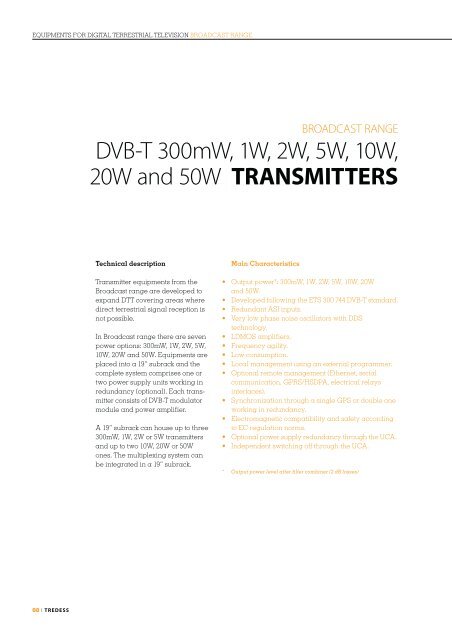
Technical description<br />
Transmitter equipments from the<br />
Broadcast range are developed to<br />
exp<strong>and</strong> DTT covering areas where<br />
direct terrestrial signal reception is<br />
not possible.<br />
In Broadcast range there are seven<br />
power options: <strong>300mW</strong>, <strong>1W</strong>, <strong>2W</strong>, <strong>5W</strong>,<br />
<strong>10W</strong>, <strong>20W</strong> <strong>and</strong> <strong>50W</strong>. Equipments are<br />
placed into a 19” subrack <strong>and</strong> the<br />
complete system comprises one or<br />
two power supply units working in<br />
redundancy (optional). Each transmitter<br />
consists of <strong>DVB</strong>-T modulator<br />
module <strong>and</strong> power amplifier.<br />
A 19” subrack can house up to three<br />
<strong>300mW</strong>, <strong>1W</strong>, <strong>2W</strong> or <strong>5W</strong> transmitters<br />
<strong>and</strong> up to two <strong>10W</strong>, <strong>20W</strong> or <strong>50W</strong><br />
ones. The multiplexing system can<br />
be integrated in a 19” subrack.<br />
Main Characteristics<br />
� �����������������������������������<br />
<strong>and</strong> <strong>50W</strong>.<br />
� ��������������������������������������������<br />
� �������������������<br />
� ����������������������������������� <br />
technology.<br />
� ���������������<br />
� �����������������<br />
� ���������������<br />
� �����������������������������������������<br />
� ���������������������������������������� <br />
communication, GPRS/HSDPA, electrical relays<br />
interfaces).<br />
� �������������������������������������������<br />
working in redundancy.<br />
� ����������������������������������������������<br />
to EC regulation norms.<br />
� �������������������������������������������<br />
� �������������������������������������<br />
* Output power level after filter combiner (2 dB losses)
Three multiplex<br />
<strong>300mW</strong>, <strong>1W</strong>, <strong>2W</strong> or<br />
<strong>5W</strong> modular <strong>DVB</strong>-T<br />
transmitter<br />
Two multiplex <strong>10W</strong>,<br />
<strong>20W</strong> or <strong>50W</strong> modular<br />
<strong>DVB</strong>-T transmitter<br />
T V BROADC ASTING I 09
10 I TREDESS<br />
<strong>DVB</strong>-T <strong>300mW</strong>, <strong>1W</strong> <strong>and</strong> <strong>2W</strong> TRANSMITTERS I REFERENCES AND SPECIFICATIONS<br />
References 853021 853022 853023 853001 853002 853003 853004 853005 853006<br />
Denomination TXGB 1C-<br />
<strong>300mW</strong><br />
TXGB 2C-<br />
<strong>300mW</strong><br />
TXGB 3C-<br />
<strong>300mW</strong><br />
VF (Forced ventilation) 853015 853016 853017<br />
TECHNICAL SPECIFICATIONS<br />
<strong>DVB</strong>-T Modulator. Modes<br />
FFT 2K, 8K<br />
Guard interval 1/4, 1/8, 1/16, 1/32<br />
FEC 1/2, 2/3, 3/4, 5/6, 7/8<br />
Constellation QPSK, 16 QAM, 64 QAM<br />
Network MFN & SFN<br />
B<strong>and</strong>width 6, 7, 8 MHz<br />
<strong>DVB</strong>-T Modulator. Inputs<br />
MPEG2 2 ASI (with redundancy), female BNC 75 Ω<br />
10MHZ (SFN) SYNCHRONIZATION INPUT<br />
Connector BNC female (back of module)<br />
Input level range -10 to +10 dBm<br />
Impedance 50 Ω<br />
1 PPS SYNCHRONIZATION INPUT<br />
Connector BNC female (back of module)<br />
Level 0 - 5 V<br />
Trigger Selected by rise-edge or fall-edge<br />
Local Oscillators<br />
Phase noise ≥90 dBc/Hz @ 1kHz<br />
Frequency steps 1 Hz<br />
Frequency stability with temperature<br />
(-10 to 60ºC) (without GPS external input)<br />
Frequency stability for a year<br />
(without GPS external input)<br />
RF output<br />
TXGB 1C-<strong>1W</strong> TXGB 2C-<strong>1W</strong> TXGB 3C-<strong>1W</strong> TXGB 1C-<strong>2W</strong> TXGB 2C-<strong>2W</strong> TXGB 3C-<strong>2W</strong><br />
± 1 x 10e-6 (-10 to +60ºC) (st<strong>and</strong>ard) ± 5 x 10e-9 (-10 to +60ºC) (optional)<br />
± 1 x 10e-6 (st<strong>and</strong>ard) ± 5 x 10e-8 (optional)<br />
Frequency range 470 – 860 MHz<br />
Output power (after �lter combiner)* <strong>300mW</strong> <strong>1W</strong> <strong>2W</strong><br />
Distance to the shoulders >38 dB<br />
MER >34 dB<br />
Power stability ≤ ± 0’5 dB<br />
Return losses > 20 dB<br />
Spurious emissions out of channel < -60 dBc<br />
Impedance 50 Ω<br />
Connector BNC Female<br />
Power test output<br />
Coupling 27 ± 3dB<br />
Connector Female BNC<br />
IF test output<br />
Output level -35 dBm<br />
Central frequency 36’15 MHz<br />
Connector Female SMB<br />
Local oscillator test output<br />
Output level -30 ± 3 dBm<br />
Connector Female SMB<br />
Status indicators<br />
<strong>DVB</strong>-T Modulator module LED (green, yellow <strong>and</strong> red)<br />
Green Normal work<br />
Yellow Output power level decreasing more than 3dB. Error in the ASI signals. No 10MHz external signal (GPS). Error in the 1 pps signal. Error in MIP.<br />
No output level (FI) in the modulator. Decoupling of local oscillators. High re�ected power. High temperature. Power ampli�er control currents<br />
out of range.<br />
Red Output power level decreasing more than 6dB.<br />
Power ampli�er module Green light: Switched on in normal work; blinking if alarms.<br />
General<br />
Control <strong>and</strong> monitoring RS-232, Ethernet, Relays, GSM/GPRS<br />
Input voltage range 220 Vac ± 15%<br />
Consumption 3<strong>1W</strong> 6<strong>2W</strong> 93W 36W 7<strong>2W</strong> 108W 36W 7<strong>2W</strong> 108W<br />
Temperature range 0 to 45ºC<br />
Power factor 0’6<br />
Dimensions (width / height / depth) 19” / 5HU / 250 mm<br />
Weight 6kg 7’5kg 10kg 6kg 7’5kg 10kg 6kg 7’5kg 10kg<br />
Ventilation Passive Passive (active as option) Passive<br />
* Output power level after �lter combiner (2 dB losses). The output power at the ampli�er’s output connector is 501mW (27dBm) for the <strong>300mW</strong> transmitter, 1’6W<br />
(32dBm) for the <strong>1W</strong> transmitter <strong>and</strong> 3’<strong>2W</strong> (35dBm) for the <strong>2W</strong> transmitter.
<strong>DVB</strong>-T <strong>5W</strong>, <strong>10W</strong>, <strong>20W</strong> <strong>and</strong> <strong>50W</strong> TRANSMITTERS I REFERENCES AND SPECIFICATIONS<br />
References 853012 853013 853014 853010 853011 853018 853019<br />
Denomination TXGB(VF)<br />
1C-<strong>5W</strong><br />
TXGB(VF)<br />
2C-<strong>5W</strong><br />
TXGB(VF)<br />
3C-<strong>5W</strong><br />
Passive ventilation 853007 853008 853009<br />
TECHNICAL SPECIFICATIONS<br />
<strong>DVB</strong>-T Modulator. Modes<br />
FFT 2K, 8K<br />
Guard interval 1/4, 1/8, 1/16, 1/32<br />
FEC 1/2, 2/3, 3/4, 5/6, 7/8<br />
Constellation QPSK, 16 QAM, 64 QAM<br />
Network MFN & SFN<br />
B<strong>and</strong>width 6, 7, 8 MHz<br />
<strong>DVB</strong>-T Modulator. Inputs<br />
MPEG2 2 ASI (with redundancy), female BNC 75 Ω<br />
10MHZ (SFN) SYNCHRONIZATION INPUT<br />
Connector BNC female (back of module)<br />
Input level range -10 to +10 dBm<br />
Impedance 50 Ω<br />
1 PPS SYNCHRONIZATION INPUT<br />
Connector BNC female (back of module)<br />
Level 0 - 5 V<br />
Trigger Selected by rise-edge or fall-edge<br />
Local Oscillators<br />
Phase noise ≥90 dBc/Hz @ 1kHz<br />
Frequency steps 1 Hz<br />
Frequency stability with temperature<br />
(-10 to 60ºC) (without GPS external input)<br />
Frequency stability for a year<br />
(without GPS external input)<br />
RF output<br />
TXGB 1C-<strong>10W</strong> TXGB 2C-<strong>10W</strong> TXGB 1C-<strong>20W</strong> TXGB 2C-<strong>20W</strong> TXGB 1C-<strong>50W</strong> TXGB 2C-<strong>50W</strong><br />
± 1 x 10e-6 (-10 to +60ºC) (st<strong>and</strong>ard) ± 5 x 10e-9 (-10 to +60ºC) (optional)<br />
± 1 x 10e-6 (st<strong>and</strong>ard) ± 5 x 10e-8 (optional)<br />
Frequency range 470 – 860 MHz<br />
Output power (after �lter combiner)* <strong>5W</strong> <strong>10W</strong> <strong>20W</strong> <strong>50W</strong><br />
Distance to the shoulders >38 dB<br />
MER >34 dB<br />
Power stability ≤ ± 0’5 dB<br />
Return losses > 20 dB<br />
Spurious emissions out of channel < -60 dBc<br />
Impedance 50 Ω<br />
Connector BNC Female Type N Female<br />
Power test output<br />
Coupling 27 ± 3dB<br />
Connector Female BNC<br />
IF test output<br />
Output level -35 dBm<br />
Central frequency 36’15 MHz<br />
Connector Female SMB<br />
Local oscillator test output<br />
Output level -30 ± 3 dBm<br />
Connector Female SMB<br />
Status indicators<br />
<strong>DVB</strong>-T Modulator module LED (green, yellow <strong>and</strong> red)<br />
Green Normal work<br />
Yellow Output power level decreasing more than 3dB. Error in the ASI signals. No 10MHz external signal (GPS). Error in the 1 pps signal. Error in MIP.<br />
No output level (FI) in the modulator. Decoupling of local oscillators. High re�ected power. High temperature.<br />
Red Output power level decreasing more than 6dB.<br />
Power ampli�er module Green light: Switched on in normal work; blinking if alarms.<br />
General<br />
Control <strong>and</strong> monitoring RS-232, Ethernet, Relays, GSM/GPRS<br />
Input voltage range 220 Vac ± 15%<br />
Consumption 90W 180W 270W 130W 260W 200W 400W 400W 800W<br />
Temperature range 0 to 45ºC<br />
Power factor 0’6<br />
Dimensions (width / height / depth) 19” / 5HU / 250 mm<br />
Weight 6kg 8’5kg 13kg 9kg 14’5kg 9kg 14’5kg 9kg 14’5kg<br />
Ventilation Active (passive as option) Active (forced ventilation)<br />
* Output power level after �lter combiner (2dB losses). The output power at the ampli�er´s output connector is 7’9W (39dBm) for the <strong>5W</strong> transmitter, 15’8W (42 dBm) for<br />
the <strong>10W</strong> transmitter, 31’6W (45 dBm) for the <strong>20W</strong> transmitter <strong>and</strong> 80W (49 dBm) for the <strong>50W</strong> transmitter.<br />
T V BROADC ASTING I 11