installation instructions and owner's manual - Mr. Heater
installation instructions and owner's manual - Mr. Heater
installation instructions and owner's manual - Mr. Heater

Create successful ePaper yourself
Turn your PDF publications into a flip-book with our unique Google optimized e-Paper software.
Serial Number Info on Pg 24<br />
Installer: Leave this <strong>manual</strong> with the appliance. Consumer: Retain this <strong>manual</strong> for future reference.<br />
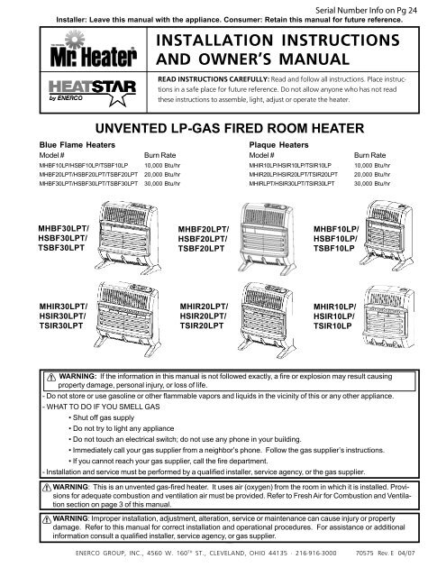
UNVENTED LP-GAS FIRED ROOM HEATER<br />
Blue Flame <strong>Heater</strong>s Plaque <strong>Heater</strong>s<br />
Model # Burn Rate Model # Burn Rate<br />
MHBF10LP/HSBF10LP/TSBF10LP 10,000 Btu/hr MHIR10LP/HSIR10LP/TSIR10LP 10,000 Btu/hr<br />
MHBF20LPT/HSBF20LPT/TSBF20LPT 20,000 Btu/hr MHIR20LP/HSIR20LPT/TSIR20LPT 20,000 Btu/hr<br />
MHBF30LPT/HSBF30LPT/TSBF30LPT 30,000 Btu/hr MHIRLPT/HSIR30LPT/TSIR30LPT 30,000 Btu/hr<br />
MHBF30LPT/<br />
HSBF30LPT/<br />
TSBF30LPT<br />
MHIR30LPT/<br />
HSIR30LPT/<br />
TSIR30LPT<br />
1<br />
MHIR10LP/<br />
HSIR10LP/<br />
TSIR10LP<br />
WARNING: If the information in this <strong>manual</strong> is not followed exactly, a fire or explosion may result causing<br />
property damage, personal injury, or loss of life.<br />
- Do not store or use gasoline or other flammable vapors <strong>and</strong> liquids in the vicinity of this or any other appliance.<br />
- WHAT TO DO IF YOU SMELL GAS<br />
• Shut off gas supply<br />
• Do not try to light any appliance<br />
INSTALLATION INSTRUCTIONS<br />
AND OWNER’S MANUAL<br />
READ INSTRUCTIONS CAREFULLY: Read <strong>and</strong> follow all <strong>instructions</strong>. Place <strong>instructions</strong><br />
in a safe place for future reference. Do not allow anyone who has not read<br />
these <strong>instructions</strong> to assemble, light, adjust or operate the heater.<br />
MHBF20LPT/<br />
HSBF20LPT/<br />
TSBF20LPT<br />
MHIR20LPT/<br />
HSIR20LPT/<br />
TSIR20LPT<br />
• Do not touch an electrical switch; do not use any phone in your building.<br />
• Immediately call your gas supplier from a neighbor’s phone. Follow the gas supplier’s <strong>instructions</strong>.<br />
• If you cannot reach your gas supplier, call the fire department.<br />
MHBF10LP/<br />
HSBF10LP/<br />
TSBF10LP<br />
- Installation <strong>and</strong> service must be performed by a qualified installer, service agency, or the gas supplier.<br />
WARNING: This is an unvented gas-fired heater. It uses air (oxygen) from the room in which it is installed. Provisions<br />
for adequate combustion <strong>and</strong> ventilation air must be provided. Refer to Fresh Air for Combustion <strong>and</strong> Ventilation<br />
section on page 3 of this <strong>manual</strong>.<br />
WARNING: Improper <strong>installation</strong>, adjustment, alteration, service or maintenance can cause injury or property<br />
damage. Refer to this <strong>manual</strong> for correct <strong>installation</strong> <strong>and</strong> operational procedures. For assistance or additional<br />
information consult a qualified installer, service agency, or gas supplier.<br />
ENERCO GROUP, INC., 4560 W. 160 Installation <strong>instructions</strong> <strong>and</strong> Owner’s Manual<br />
TH ST., CLEVELAND, OHIO 44135 · 216-916-3000 70575 Rev. E 04/07
This appliance may be installed in an aftermarket* permanently manufactured (mobile) home, where not prohibited by<br />
local codes.This appliance is only for use with the type of gas indicated on the rating plate. This appliance is not<br />
convertible for use with any other gas.<br />
*Aftermarket completion of sale, not for the purpose of resale, from the manufacturer.<br />
WARNINGS<br />
IMPORTANT: Read this owner’s <strong>manual</strong> carefully<br />
<strong>and</strong> completely before trying to assemble, operate,<br />
or service this heater. Improper use of this heater<br />
can cause serious injury or death from burns, fire,<br />
explosion, electrical shock, <strong>and</strong> carbon monoxide<br />
poisoning.<br />
WARNING: This appliance is equipped for (natural<br />
or propane) gas. Field conversion is not permitted.<br />
WARNING: Do not use any accessory not approved<br />
for use with this heater.<br />
WARNING: Any change to this heater or its controls<br />
can be dangerous.<br />
• Do not place clothing or other flammable<br />
material on or near the appliance. Never<br />
place any objects on the heater.<br />
• Due to high temperatures, heater should be<br />
kept out of traffic <strong>and</strong> away from furniture <strong>and</strong><br />
draperies.<br />
• Surface of heater becomes very hot when<br />
running. Keep children <strong>and</strong> adults away from<br />
hot surfaces to avoid burns or clothing ignition.<br />
<strong>Heater</strong> will remain hot for a time after shutdown.<br />
Allow heater surfaces to cool before<br />
h<strong>and</strong>ling.<br />
• Young children should be carefully supervised<br />
when they are in the same room with heater.<br />
• Make sure grille guard is in place before<br />
running heater. If screen or grille guard is<br />
removed for servicing it must be replaced prior<br />
to operating the heater.<br />
• Keep the appliance area clear <strong>and</strong> free from<br />
combustible materials, gasoline, <strong>and</strong> other<br />
flammable vapors <strong>and</strong> liquids.<br />
PRECAUTIONS:<br />
1. BF-10 LP <strong>and</strong> IR-10LP may be installed in a bedroom,<br />
but not a bathroom, or any place where a<br />
strong wind would shut down the appliance.<br />
2. BF-20 LPT, BF-30 LPT, IR-20 LPT <strong>and</strong> IR-30 LPT<br />
may not be installed in a bedroom or bathroom, or<br />
any place where a strong wind would shut down the<br />
appliance.<br />
3. This heater needs outside ventilation air to run<br />
properly. The Oxygen Depletion Sensor (ODS)<br />
safety shutoff system shuts down the heater if not<br />
enough fresh air is available. See Fresh Air for<br />
Combustion <strong>and</strong> Ventilation, page 3.<br />
4. Keep all air openings in heater clear, free of debris or<br />
any blockage. This will ensure that enough air for<br />
proper combustion enters the heater.<br />
5. If heater shuts off, do not relight until you provide<br />
fresh, outside air. If heater keeps shutting off, it<br />
requires servicing.<br />
6. Turn off <strong>and</strong> unplug heater <strong>and</strong> let cool before<br />
servicing. Only a qualified service person should<br />
service <strong>and</strong> repair heater.<br />
7. Do not run heater:<br />
• Where flammable liquids or vapors are used or<br />
stored<br />
• During dusty conditions.<br />
8. Before using furniture polish, wax, carpet cleaner or<br />
similar products, turn heater off. If heated, the vapors<br />
from these products may create a white powder<br />
residue within burner box or on adjacent walls or<br />
furniture.<br />
9. Do not use heater if any part has been underwater.<br />
Immediately call a qualified service technician to<br />
inspect the room heater <strong>and</strong> to replace any part of<br />
the control system <strong>and</strong> any gas control which has<br />
been underwater.<br />
10.Operating heater above elevations of 4,500 feet<br />
could cause pilot/ODS to shut down heater.<br />
11.Always run heater with control knob in a locked<br />
position. Never set control knob between locked<br />
positions. Poor combustion <strong>and</strong> higher levels of<br />
carbon monoxide may result if control knob is left<br />
between locked positions.<br />
DANGER: Carbon monoxide poisoning may lead to<br />
death.<br />
Carbon Monoxide Poisoning:<br />
Early signs of carbon monoxide poisoning resemble the<br />
flu, with headaches, dizziness, or nausea. If you have<br />
these signs, the heater may not be working properly.<br />
Get fresh air at once! Have heater serviced. Some<br />
people are more affected by carbon monoxide than<br />
others. These include pregnant women, persons with<br />
heart or lung disease or anemia, those under the<br />
influence of alcohol, <strong>and</strong> those at high altitudes.<br />
Propane/LP Gas:<br />
Propane/LP gas is odorless. An odor making agent is<br />
added to propane/LP gas. The odor helps you detect a<br />
Propane/LP gas leak. However the odor added to<br />
propane/LP gas may be present even though no odor<br />
exists. Make certain you read <strong>and</strong> underst<strong>and</strong> all<br />
warnings. Keep this <strong>manual</strong> for reference. It is your<br />
guide to safe <strong>and</strong> proper operation of this heater.<br />
2 Installation <strong>instructions</strong> <strong>and</strong> Owner’s Manual 70575 Rev. E 04/07
Product Features<br />
Fan<br />
Blower<br />
Switch<br />
Burners<br />
Grill<br />
Front Panel<br />
Ignitor Button<br />
Room Temperature<br />
Thermometer LED<br />
Control Knob<br />
<strong>Heater</strong><br />
Cabinet<br />
Figure 1<br />
SAFETY DEVICE<br />
This heater has a pilot with an Oxygen Depletion Sensor<br />
(ODS) safety shut off system. The ODS/pilot shuts off<br />
the heater if there is not enough fresh air.<br />
IGNITION SYSTEM<br />
PIEZO: BF10LP/ IR10LP – The heater is equipped with a<br />
piezo <strong>manual</strong> ignitor. This system requires no matches,<br />
batteries, or other source to light heater.<br />
Electronic: BF20LPT/BF30LPT/IR20LPT/IR30LPT –<br />
The heater is equipped with an electronic <strong>manual</strong> ignitor.<br />
This system requires no matches, or other source to<br />
light heater, but does require one AA battery to operate<br />
ignitor (AA Battery included).<br />
To install or replace battery unscrew the<br />
ignitor cap (red button), insert battery <strong>and</strong><br />
replace cap.<br />
(AA Battery included)<br />
THERMOSTATIC CONTROL ON<br />
THERMOSTAT MODELS<br />
(BF20LPT, BF30LPT, IR20LPT <strong>and</strong> IR30LPT)<br />
These heaters have a control valve with a thermostat<br />
sensing bulb. This results in the greatest heater comfort<br />
<strong>and</strong> may result in lower bills.<br />
These heaters also include an electrical blower. The<br />
blower switch has three positions: MANUAL, OFF <strong>and</strong><br />
AUTO. In AUTO, the blower will turn on <strong>and</strong> off as the<br />
heater cycles on <strong>and</strong> off. In MANUAL, the blower will run<br />
continuously. To turn blower off, use the OFF position.<br />
LOCAL CODES<br />
Install <strong>and</strong> use heater with care.<br />
Installation must conform to local codes or in the absences<br />
of local codes, use the latest edition of National<br />
Fuel Gas Code ANSI Z223.1/NFPA 54.<br />
3<br />
UNPACKING<br />
1. Remove heater from carton.<br />
2. Remove all protective packaging applied to<br />
heater for shipment.<br />
3. Check heater for any shipping damage. If heater<br />
is damaged, promptly inform dealer where you<br />
bought heater.<br />
FRESH AIR FOR COMBUSTION AND<br />
VENTILATION<br />
WARNING: This heater shall not be installed in a<br />
confined space or unusually tight construction<br />
unless provisions are provided for adequate combustion<br />
<strong>and</strong> ventilation air. Read the following<br />
<strong>instructions</strong> to insure proper fresh air for this <strong>and</strong><br />
other fuel-burning appliances in your home.<br />
ESTABLISHING ADEQUATE VENTILATION<br />
The following are excerpts from National Fuel Gas<br />
Code, NFPA 54/ ANSI Z223.1, Section 5.3, Air for<br />
Combustion <strong>and</strong> Ventilation. All spaces in homes fall<br />
into one of the three following ventilation classifications:<br />
1. Unusually Tight Construction<br />
2. Unconfined Space<br />
3. Confined Space<br />
This heater must not be installed in a confined space or<br />
unusually tight construction unless provisions are<br />
provided for adequate combustion <strong>and</strong> ventilation air.<br />
The information on pages 3 through 5 will help you<br />
classify your space <strong>and</strong> provide adequate ventilation.<br />
Unusually Tight Construction<br />
If your home meets all of the three following criteria you<br />
must provide additional fresh air. See Ventilation Air<br />
from Outdoors, page 5.<br />
Unusually tight construction is defined as construction<br />
where:<br />
a. Walls <strong>and</strong> ceilings exposed to the outside atmosphere<br />
have a continuous water vapor retarder with a<br />
rating of one perm (6 x 10-11 kg per pa-sec-m2 ) or less<br />
with openings gasketed or sealed <strong>and</strong><br />
b. Weather stripping has been added on openable<br />
windows <strong>and</strong> doors, <strong>and</strong><br />
c. Caulking or sealants are applied to areas such as<br />
joints around windows <strong>and</strong> door frames, between<br />
wall-ceiling joints, between wall panels, at penetrations<br />
for plumbing, electrical, <strong>and</strong> gas lines, <strong>and</strong> at<br />
other openings.<br />
If you home does not meet all of the three criteria<br />
above, see Determining the Type of <strong>Heater</strong> Location<br />
Space, page 4.<br />
Confined Space <strong>and</strong> Unconfined Space<br />
The National Fuel Gas Code, NFPA 54/ ANSI Z223.1<br />
defines a confined space as a space whose volume is<br />
less than 50 cubic feet per 1,000 Btu per hour (4.8 m 3<br />
per kW) of the aggregate input rating of all appliances<br />
Installation <strong>instructions</strong> <strong>and</strong> Owner’s Manual
installed in that space, <strong>and</strong> an unconfined space as a<br />
space whose volume is not less than 50 cubic feet per<br />
1,000 Btu per hour (4.8 m3 per kW) of the aggregate<br />
input rating of all appliances installed in that space.<br />
Rooms communicating directly with the space in which<br />
the appliances are installed*, through openings not<br />
furnished with doors, are considered a part of the unconfined<br />
space.<br />
*Adjoining rooms are communicating only if there are<br />
doorless passageways or ventilation grilles between<br />
them.<br />
DETERMINING THE TYPE OF HEATER<br />
LOCATION SPACE:<br />
Use this method to determine if you have a confined or<br />
unconfined space.<br />
Note: the space includes the room in which you<br />
install heater plus any adjoining rooms with doorless<br />
passageways or ventilation grilles between the<br />
rooms.<br />
1. Find the volume of the space by multiplying room<br />
length x width x height.<br />
Example: Space size 18ft (length) x 18ft. (width) x 8ft.<br />
(height) = 2592<br />
If additional ventilation to adjoining room is supplied with<br />
grilles or openings, add the volume of these rooms to the<br />
total volume of the space.<br />
2. Divide the space volume by 50 cubic feet to determine<br />
the maximum Btu/hr the space can support.<br />
Example: 2592 cu.ft. (volume of space) / 50 cu.ft. = 51.8<br />
or 51,800 (maximum Btu/hr the space can<br />
support)<br />
WARNING: If the area in which the heater may be<br />
operated is smaller than defined as an unconfined<br />
space or if the building is of unusually tight construction,<br />
provide adequate combustion <strong>and</strong> ventilation air<br />
by the methods described in the National Fuel Gas<br />
Code, NFPA 54/ ANSI Z223.1, Section 5.3 or<br />
applicable local codes.<br />
3. Add the Btu/hr of all the fuel-burning appliances in the<br />
space such as, Vent–free heater, Gas water heater,<br />
Gas furnace, Vented gas heater, Gas fireplace logs,<br />
<strong>and</strong> Other gas appliances*<br />
*Do not include direct-vent gas appliances. Directvent<br />
draws combustion air from the outdoors <strong>and</strong><br />
vents to the outdoors.<br />
Example:<br />
Gas water heater 40,000 Btu/hr<br />
Vent Free <strong>Heater</strong> + 20,000 Btu/hr<br />
Total =60,000 Btu/hr<br />
4. Compare the maximum Btu/hr the space can support<br />
with the actual amount of Btu/hr used.<br />
Example: 51,800 Btu/hr (maximum Btu/hr the space<br />
can support)<br />
60,000 Btu/hr (Actual amount of Btu/hr used)<br />
The space in the above example is a confined space<br />
because the actual Btu/hr used is more than the<br />
maximum Btu/hr the space can support.<br />
You must provide additional fresh air. Your options<br />
are as follows:<br />
A. Rework worksheet, <strong>and</strong> the space of an adjoining<br />
room. If the extra space provides an unconfined<br />
space, remove door to adjoining room or add ventilation<br />
grilles between the rooms. See Ventilation Air<br />
From Inside Building (Fig. 2)<br />
B. Vent room directly to the outdoors. See Ventilation Air<br />
From Outdoors (Fig. 3).<br />
C. Install a lower Btu/hr heater if lower Btu/hr size makes<br />
room unconfined.<br />
If actual Btu/hr used is less than the maximum Btu/<br />
hr the space can support, the space is an unconfined<br />
space. You will need no additional fresh air<br />
ventilation.<br />
VENTILATION AIR<br />
Ventilation from Inside Building<br />
This fresh air would come from an adjoining unconfined<br />
space. When ventilation to an adjoining unconfined<br />
space, you must provide two permanent openings: one<br />
within 12” of the ceiling <strong>and</strong> one within 12” of the floor on<br />
the wall connecting the two spaces (see options 1 & 2 of<br />
fig. 2). You can also remove door into adjoining room<br />
(see option3, fig 2). Follow the National Fuel Gas Code<br />
NFPA 54/ ANSI Z223.1, Section 5.3, Air for Combustion<br />
<strong>and</strong> Ventilation for required size of ventilation grills or<br />
ducts.<br />
Ventilation<br />
Grilles into<br />
Adjoining<br />
Room -<br />
Option 1<br />
Or remove<br />
door into<br />
Adjoining<br />
Room -<br />
Option 3<br />
Ventilation Grilles<br />
into Adjoining Room<br />
- Option 2<br />
Figure 2<br />
WARNING: Rework worksheet, adding the space of<br />
the adjoining unconfined space. The combined<br />
space must have enough fresh air to supply all<br />
appliances in both spaces.<br />
4 Installation <strong>instructions</strong> <strong>and</strong> Owner’s Manual 70575 Rev. E 04/07<br />
12”<br />
12”
OUTLET<br />
AIR<br />
INLET<br />
AIR<br />
OUTLET AIR<br />
12<br />
12<br />
12<br />
12<br />
12<br />
12<br />
12<br />
12<br />
12<br />
12345<br />
12345<br />
12345<br />
12345<br />
12345<br />
12345678<br />
12345678<br />
12345678<br />
12345<br />
12345<br />
12345<br />
VENTILATION AIR<br />
123456<br />
123456<br />
123456<br />
123456<br />
123456<br />
12345<br />
12345<br />
12345<br />
VENTILATED<br />
ATTIC<br />
TO ATTIC<br />
TO CRAWL<br />
SPACE<br />
VENTILATION CRAWL SPACE<br />
Figure 3.<br />
Ventilation from Outdoors<br />
If necessary, provide extra fresh air by using ventilation<br />
grilles or ducts. Connect these items directly to the<br />
outdoors or spaces open to the outdoors. These<br />
include attics* <strong>and</strong> crawl spaces. Follow the National<br />
Fuel Gas Code NFPA 54/ ANSI Z223.1, Section 5.3, Air<br />
for Combustion <strong>and</strong> Ventilation for required size of<br />
ventilation grilles or ducts.<br />
*IMPORTANT: Do not provide openings for inlet or<br />
outlet into attic. If attic has a thermostat-controlled<br />
power vent, heated air entering the attic will activate<br />
the power vent.<br />
IMPORTANT: Vent-free heaters add moisture to the<br />
air. Although this is beneficial, installing heater in<br />
rooms without enough ventilation air may cause<br />
mildew to form from too much moisture. See Fresh<br />
Air for Combustion <strong>and</strong> Ventilation, pages 3 through<br />
5.<br />
INSTALLATION<br />
NOTICE: This heater is intended for use as supplemental<br />
heat. Use this heater along with your primary heating<br />
system. Do not install this heater as your primary heat<br />
source. If you have a central heating system, you may<br />
run system’s circulating blower while using heater. This<br />
will help circulate the heat throughout the house. In the<br />
event of a power outage, you can use this heater as your<br />
primary heat source for the duration of the outage.<br />
WARNING: A qualified service person must install<br />
heater. Follow all local codes.<br />
CHECK GAS TYPE<br />
Use only LP-gas. If your gas supply is not LP-gas, do<br />
not install heater. Call dealer where you bought heater<br />
for proper type heater.<br />
THIS INSTALLATION REQUIRES:<br />
Before installing heater, make sure you have the items<br />
listed below:<br />
• Piping (check local codes)<br />
• Sealant (resistant to LP_Gas)<br />
• Equipment shutoff valve*<br />
5<br />
• Ground joint union<br />
• Test gauge connection*<br />
• Sediment trap<br />
• Tee joint<br />
• Pipe wrench<br />
*A CSA/AGA certified equipment shutoff valve with 1/8”<br />
NPT tap is an acceptable alternative to test gauge<br />
connection. Purchase a CSA/AGA certified equipment<br />
shutoff valve from your dealer. See Accessories, page<br />
17.<br />
LOCATING HEATER<br />
This heater is designed to be mounted on the wall. The<br />
heater can also be located on a non-combustible floor,<br />
away from a wall by using the floor mounting st<strong>and</strong>s<br />
included with the heater. If installed on combustible<br />
flooring such as carpeting, tile or other combustible<br />
material other than wood flooring, the heater must be<br />
placed on a wood panel the full width <strong>and</strong> depth of the<br />
appliance.<br />
For convenience <strong>and</strong> efficiency, install the heater:<br />
• Where there is easy access for operation,<br />
inspection, <strong>and</strong> service.<br />
• In the coldest part of the room.<br />
• If planning to use fan, locate heater near an<br />
electrical outlet.<br />
CAUTION: If you install the heater in a home garage:<br />
• <strong>Heater</strong> pilot <strong>and</strong> burner must be at least 18<br />
inches above floor.<br />
• Locate heater where moving vehicle will not hit it.<br />
CAUTION:This heater creates warm air currents.<br />
These currents move heat to wall surfaces next to heater.<br />
Installing heater next to vinyl or cloth wall covering or<br />
operating heater where impurities (such as tobacco smoke,<br />
aromatic c<strong>and</strong>les, cleaning fluids, oil or kerosene lamps,<br />
etc.) are present in the air may discolor walls.<br />
WARNING: Never install the heater:<br />
• In a bathroom.<br />
• In a bedroom (IR20LPT, IR30LPT, BF20LPT or<br />
BF30LPT)<br />
• In a recreational vehicle.<br />
• Where curtains, furniture, clothing, or other<br />
flammable objects are less than 36 inches from<br />
the front, top, or sides of the heater.<br />
• As a fireplace insert<br />
• In high-traffic areas<br />
• In windy or drafty areas<br />
WARNING: <strong>Heater</strong> must be mounted to maintain the<br />
minimum clearances shown in Figure 4. If possible,<br />
provide greater clearances from the floor, ceiling, <strong>and</strong><br />
joining walls.<br />
Installation <strong>instructions</strong> <strong>and</strong> Owner’s Manual
Left<br />
Side Right<br />
Side<br />
Floor<br />
6” Min from<br />
adjoining<br />
walls<br />
2” min. to top surface of carpet,<br />
tile or other combustible material<br />
36” min. from<br />
ceiling<br />
Figure 4<br />
FASTENING HEATER TO WALL<br />
Mounting Bracket<br />
The mounting bracket in located on the back panel of<br />
heater (see figure 5). It has been taped there for shipping.<br />
Remove mounting bracket from back panel.<br />
Mounting<br />
Bracket<br />
Figure 5<br />
Removing Front Panel of <strong>Heater</strong><br />
1. Remove three screws on bottom front of front<br />
panel.<br />
2. Pull bottom of front panel forward, then down<br />
(see figure 6)<br />
Figure 6<br />
Attaching Mounting Bracket to Wall<br />
Use holes on each end of mounting bracket to attach<br />
bracket to wall. These holes are 16 inches apart. Attach<br />
mounting bracket to wall in one of two following ways.<br />
1. Attach to wall studs<br />
2. Attach to wall anchor<br />
Attaching to Wall Stud:<br />
This way is the best providing the strongest mounting in<br />
wood frame houses.<br />
Attaching to Wall Anchor:<br />
This way allows you to attach mounting bracket to<br />
hollow walls (wall areas between studs) or to solid walls<br />
(concrete or masonry).<br />
Decide which way best suits your needs. Either method<br />
will provide a secure hold for the mounting bracket.<br />
1. Tape mounting bracket to wall where heater will<br />
be located. Make sure mounting bracket is<br />
level. For wall stud mounting locate one end of<br />
the mounting bracket over a wall stud.<br />
WARNING: Maintain minimum clearances<br />
shown in figure 7. If you can, provide greater<br />
clearances from the floor <strong>and</strong> joining wall.<br />
2. Mark screw locations on wall (see figure 7).<br />
3. Remove tape <strong>and</strong> mount bracket from wall.<br />
Adjoining Wall<br />
6-1/2” Min. 10,000 BTU<br />
10-1/4” min 20,000-30,000 BTU<br />
16” (Lg)<br />
12-9/64” (Sm)<br />
Mark mounting hole locations<br />
<strong>and</strong> drill holes where indicated.<br />
Allow for minimum clearances<br />
17-1/2” Min.<br />
123456789012345678901234567890121<br />
123456789012345678901234567890121<br />
123456789012345678901234567890121<br />
123456789012345678901234567890121<br />
Figure 7<br />
Attaching to Wall Stud:<br />
For attaching mounting bracket to wall studs<br />
1. Drill holes at marked locations using 9/64” drill<br />
bit.<br />
2. Place mounting bracket onto wall. Line up holes<br />
on each end of bracket with hole drilled in wall.<br />
3. Insert mounting screws through bracket <strong>and</strong><br />
into wall studs.<br />
4. Tighten screws until mounting bracket is firmly<br />
fastened to wall studs.<br />
Attaching to Wall using Anchor:<br />
For attaching mounting bracket to hollow walls (wall<br />
areas between studs) or solid walls (concrete or masonry)<br />
Note: Wall anchors, mounting screws, <strong>and</strong> spacer<br />
are in hardware package. The hardware package is<br />
provided with heater.<br />
123456789012345678901234567890121<br />
6 Installation <strong>instructions</strong> <strong>and</strong> Owner’s Manual 70575 Rev. E 04/07
1. Drill holes at marked locations using 5/16” drill<br />
bit. For solid walls (concrete or masonry), drill<br />
at least 1” deep.<br />
2. Fold wall anchor as shown in figure 8 below.<br />
Figure 8.<br />
3. Insert wall anchor (wings first) into hole. Tap<br />
anchor flush to wall.<br />
4. For thin walls (1/2” or less) insert red key into<br />
wall anchor.<br />
5. Place mounting bracket onto wall. Line up holes<br />
on each end of bracket with wall anchors.<br />
6. Insert mounting screws through bracket <strong>and</strong><br />
into wall anchors.<br />
7. Tighten screws until mounting bracket is firmly<br />
fastened to wall.<br />
Placing <strong>Heater</strong> on Mounting Bracket<br />
1. Locate two horizontal slots on back pane of<br />
heater (see figure 19).<br />
2. Place heater onto mounting bracket. Slide<br />
horizontal slots onto st<strong>and</strong>-out tabs on mounting<br />
bracket.<br />
Horizontal Slots<br />
Mounting Bracket<br />
mounted to wall<br />
Figure 9<br />
Installing Bottom Mounting Screws<br />
1. Locate two bottom mounting holes. These holes<br />
are near bottom on back panel of heater (see<br />
figure 10).<br />
2.<br />
Figure 10<br />
Mark screw locations on wall.<br />
3. Remove heater from mounting bracket.<br />
7<br />
4. If installing bottom mounting screw into hollow or<br />
solid wall, install wall anchors. Follow steps 1<br />
through 4 under Attaching to Wall using Anchor.<br />
If installing bottom mounting screw into wall<br />
stud, drill holes at marked locations using 9/64”<br />
drill bit.<br />
5. Re-place heater onto mounting bracket.<br />
6. Place spacers between bottom mounting holes<br />
<strong>and</strong> wall anchor or drilled hole.<br />
7. Hold spacer in place with one h<strong>and</strong>. With the<br />
other h<strong>and</strong>, insert mounting screw through<br />
bottom mounting hole <strong>and</strong> spacer. Place tip of<br />
screw in opening of wall anchor or drilled hole.<br />
8. Tighten both screws until heater is firmly<br />
secured to wall. Do not over tighten.<br />
Note: Do not replace front panel at this time. Replace<br />
front panel after making gas connections <strong>and</strong><br />
checking for leaks.<br />
FLOOR MOUNTING AWAY FROM WALL:<br />
Figure 11<br />
Installing Support Feet (see figure 11)<br />
1. Lay heater onto table on its back with bottom<br />
edge overhanging table edge.<br />
2. Securely attach feet to bottom of heater using 2<br />
– self-tapping screws each.<br />
Note: Feet should have long end going out the front<br />
of heater, <strong>and</strong> the edge coinciding with side of<br />
heater. If feet overhang side of the heater, switch<br />
leg location.<br />
3. Place heater on non-combustible surface (see<br />
Locating <strong>Heater</strong> above) before proceeding with<br />
gas connection. If this will be a permanent<br />
location, heater may be locked into position<br />
using anchoring holes in mounting feet.<br />
Note: Use of floor mounting feet will require you to<br />
use a 3/8 NPT street elbow to make gas connection.<br />
CONNECTING TO GAS SUPPLY<br />
WARNING: A qualified service person must connect<br />
heater to gas supply. Follow all local codes.<br />
Installation <strong>instructions</strong> <strong>and</strong> Owner’s Manual
WARNING: This appliance requires a 3/8” NPT<br />
(National Pipe Thread) inlet connection to the<br />
pressure regulator. Use of floor mounting feet will<br />
require you to use a 3/8 NPT street elbow to make<br />
gas connection.<br />
CAUTION: Never connect heater directly to the Propane<br />
supply. This heater requires an external regulator (not<br />
supplied). Install the external regulator between the heater<br />
<strong>and</strong> Propane/LP supply.<br />
The installer must supply an external regulator. The<br />
external regulator will reduce the incoming gas pressure<br />
to between 11 <strong>and</strong> 14 inches of water. If you do not<br />
reduce incoming gas pressure heater regulator damage<br />
could occur. Install external regulator with the vent<br />
pointing down as shown in Figure 12. Pointing the vent<br />
down protects it from freezing rain or sleet.<br />
CAUTION: Use only new black iron or steel pipe.<br />
Internally-tinned copper tubing may be used in certain<br />
areas. Check your local codes. Use pipe of large<br />
enough diameter to allow proper gas volume to heater.<br />
If pipe is too small, undue loss of pressure will occur.<br />
Installation must include an equipment shutoff valve,<br />
union <strong>and</strong> plugged 1/8” NPT tap. Locate NPT tap within<br />
reach of test gauge hookup. NPT tap must be upstream<br />
from heater (see figure 12).<br />
3/8” NPT Pipe Nipple<br />
Ground Joint Union<br />
Equipment<br />
Shutoff Valve<br />
From Gas Meter<br />
(4” W.C. to 10.5”<br />
W.C. Pressure)<br />
3” Minimum<br />
Pressure<br />
Regulator<br />
<strong>Heater</strong><br />
Cabinet<br />
Test Gauge<br />
Connection<br />
Tee Joint<br />
Reducer Bushing<br />
to 1/8” NPT<br />
Tee Joint<br />
Pipe Nipple<br />
Cap<br />
1/8” NPT Plug Tap<br />
Sediment<br />
Trap<br />
Figure 12<br />
*A CSA/AGA certified equipment shutoff valve with 1/8”<br />
NPT tap is an acceptable alternative to test gauge<br />
connection. Purchase the CSA/AGA certified equipment<br />
shutoff valve from your dealer. See Accessories,<br />
page 17.<br />
IMPORTANT: Install an equipment shutoff valve in an<br />
accessible location. The equipment shutoff valve is for<br />
turning on or shutting off the gas to the appliance.<br />
Apply pipe joint sealant lightly to male threads. This will<br />
prevent excess sealant from going into pipe. Excess<br />
sealant in pipe could result in clogged heater fuel train.<br />
CAUTION: Use pipe joint sealant that is resistant to<br />
LP-Gas.<br />
Install sediment trap in supply line as shown in figure 12.<br />
Locate sediment trap where it is within reach for cleaning.<br />
A sediment trap traps moisture <strong>and</strong> contaminants.<br />
This keeps them from going into heater. If sediment trap<br />
is not installed or is installed improperly, heater may not<br />
run correctly.<br />
IMPORTANT: Hold pressure regulator with wrench<br />
when connecting it to gas piping <strong>and</strong>/or fittings.<br />
CHECKING GAS CONNECTIONS<br />
WARNING: Test all gas piping <strong>and</strong> connections for<br />
leaks after installing or servicing. Correct all leaks<br />
at once.<br />
WARNING: Never use an open flame to check for a<br />
gas leak. Apply a mixture of liquid soap <strong>and</strong> water to<br />
all joints. Bubbles forming show a leak. Correct all<br />
leaks at once.<br />
PRESSURE TESTING GAS SUPPLY PIPING<br />
SYSTEM<br />
Test pressure in Excess of ½ psig (3.5kPa)<br />
1. Disconnect appliance with its appliance main<br />
gas valve (control valve) <strong>and</strong> equipment shutoff<br />
valve from gas supply piping system. Pressures<br />
in excess of ½ psig will damage heater<br />
regulator.<br />
2. Cap off open end of gas pipe where equipment<br />
shutoff valve was connected.<br />
3. Pressurize supply piping system by either using<br />
compressed air or opening main gas valve on<br />
or near gas meter.<br />
4. Check all connections <strong>and</strong> joints in gas supply<br />
piping system. Apply mixture of liquid soap <strong>and</strong><br />
water to gas joints. Bubbles forming show a<br />
leak.<br />
5. Correct all leaks at once.<br />
6. Depressurize <strong>and</strong> relieve pressure in supply<br />
piping system.<br />
7. Reconnect heater <strong>and</strong> equipment shutoff valve<br />
to gas supply.<br />
8. Reconnected fittings must be checked for leaks<br />
in next section.<br />
Test Pressure Equal To or Less Than ½ psig (3.5 kPa)<br />
1. Close equipment shutoff valve (see figure 13).<br />
2. Pressurize supply piping system by either using<br />
compressed air or opening propane/LP supply<br />
valve.<br />
3. Check all joints from the propane/LP supply<br />
valve to equipment shutoff valve (see figure 14).<br />
Apply mixture of liquid soap <strong>and</strong> water to gas<br />
joints. Bubbles forming show a leak.<br />
4. Correct all leaks at once.<br />
5. Depressurize <strong>and</strong> relieve pressure from supply<br />
piping system.<br />
8 Installation <strong>instructions</strong> <strong>and</strong> Owner’s Manual 70575 Rev. E 04/07
Pressure Testing <strong>Heater</strong> Gas Connections:<br />
1. Make sure that the heater supply piping system<br />
is connected <strong>and</strong> has been leak tested as<br />
described above.<br />
2. Make sure control knob of heater is in OFF<br />
position.<br />
3. Open equipment shutoff valve (see figure 13).<br />
4. Open propane/LP supply valve.<br />
5. Check all joints from equipment shutoff valve to<br />
control valve (see figure 14). Apply mixture of<br />
liquid soap <strong>and</strong> water to gas joints. Bubbles<br />
forming show a leak.<br />
6. Correct all leaks at once.<br />
7. Light heater (see Operating Your <strong>Heater</strong>, pages<br />
11 <strong>and</strong> 12 for thermostat models or pages 9 <strong>and</strong><br />
10 for non-thermostat models). Check the rest<br />
of the internal joints for leaks.<br />
8. Turn off heater (see To Turn OFF Gas to<br />
Appliance, page 12 for thermostat models <strong>and</strong><br />
page 11 for non-thermostat models).<br />
9. Replace lower front panel.<br />
Gas Meter<br />
Equipment<br />
Shutoff Valve<br />
Open<br />
Figure 13<br />
Figure 14<br />
Equipment<br />
Shutoff Valve<br />
Closed<br />
Control Valve<br />
9<br />
ELECTRICAL WIRING DIAGRAM:<br />
Figure 15<br />
If any original wiring as supplied with the heater must be<br />
replaced, it must be replaced with type AWG 105oC wire<br />
or its equivalent except as indicated.<br />
WARNING: Electrical Grounding Instructions: This<br />
heater is equipped with a three-prong (grounding)<br />
plug for your protection against shock hazard <strong>and</strong><br />
should be plugged into a properly grounded threeprong<br />
receptacle.<br />
OPERATING YOUR HEATER<br />
NON-THERMOSTAT MODELS<br />
IR10LP / BF10LP<br />
FOR YOUR SAFETY READ BEFORE LIGHTING<br />
WARNING: If you do not follow these <strong>instructions</strong><br />
exactly, a fire or explosion may result causing<br />
property damage, personal injury or loss of life.<br />
A. This appliance has a pilot that must be lighted<br />
by h<strong>and</strong>. When lighting the pilot, follow these<br />
<strong>instructions</strong> exactly.<br />
B. BEFORE LIGHTING smell all around the<br />
appliance area for gas. Be sure to smell next to<br />
the floor because some gas is heavier than air<br />
<strong>and</strong> will settle on the floor.<br />
WHAT TO DO IF YOU SMELL GAS<br />
• Do not try to light any appliance.<br />
• Do not touch any electrical switch; do not use<br />
any phone in your building.<br />
• Immediately call you gas supplier from a<br />
neighbor’s phone. Follow the gas supplier’s<br />
<strong>instructions</strong>.<br />
• If you can not reach your gas supplier, call the<br />
fire department.<br />
Installation <strong>instructions</strong> <strong>and</strong> Owner’s Manual
C. Use only your h<strong>and</strong> to push in or turn the gas<br />
control knob. Never use tools. If knob will not<br />
push in or turn by h<strong>and</strong>, don’t try to repair it; call<br />
a qualified service technician or gas supplier.<br />
Force or attempted repair may result in a fire or<br />
explosion.<br />
D. Do not use this appliance if any part has been<br />
underwater. Immediately call a qualified service<br />
technician to inspect the appliance <strong>and</strong> to<br />
replace any part of the control system which<br />
has been underwater.<br />
LIGHTING INSTRUCTIONS<br />
1. STOP! Read all safety information included with<br />
<strong>and</strong> on the side of heater.<br />
2. Check that gas supply to heater is on.<br />
3. Push in gas control knob <strong>and</strong> slightly turn<br />
clockwise to the OFF position (see figure 16).<br />
Note: Knob cannot be turned from PILOT to OFF<br />
unless knob is pushed in slightly. Do not force.<br />
4. Wait five (5) minutes. Then smell for gas,<br />
including near the floor. If you smell gas,<br />
STOP! Follow “B” in the safety information<br />
above. If you do not smell gas, go to the next<br />
step.<br />
5. Push in gas control knob slightly <strong>and</strong> turn<br />
counterclockwise to PILOT/IGN <strong>and</strong> depress for<br />
five (5) seconds.<br />
Note: The first time that the heater is operated after<br />
connecting the gas supply, the control knob should<br />
be depressed for about 30 seconds. This will allow<br />
air to bleed from the gas system.<br />
6. Push in control knob <strong>and</strong> rotate control knob<br />
back to OFF position then rotate counterclockwise<br />
to PILOT/IGN position. This will light pilot.<br />
If needed, gently keep rotating control knob back<br />
<strong>and</strong> forth while depressed until pilot lights.<br />
7. Keep control knob depressed in for ten (10)<br />
seconds after lighting pilot. If pilot goes out,<br />
repeat steps 4, 5, 6 <strong>and</strong> 7.<br />
• If pilot does not stay lit, refer to Troubleshooting,<br />
pages 14 & 15. Also, contact a qualified service<br />
person or gas supplier for repairs.<br />
• If control knob does not pop up when released,<br />
contact a qualified service person or gas<br />
supplier for repairs.<br />
8. FOR IR10LP: When the pilot is lit, turn the<br />
control knob to “LO” position to light heater.<br />
Leave on “LO” position until first burner tile has<br />
turned bright red (See figure18).<br />
FOR BF10LP: When the pilot is lit, turn the<br />
control knob to “HI” position to light heater.<br />
9. FOR IR10LP: After first burner tile has turned<br />
bright red, adjust heat output by turning control<br />
knob to desired position (“LO” or “HI”, figure 18).<br />
Do not operate heater between locked positions.<br />
FOR BF10LP: After flame is established (see Burner<br />
Flame Pattern, Pages 12 <strong>and</strong> 13) on “HI”, adjust heat<br />
output by turning control knob to desired position<br />
(“LO” or “HI”). Do not operate heater between locked<br />
positions.<br />
Control Knob<br />
Figure 16<br />
Note: Your heater may have either pilot assembly.<br />
CAUTION: Do not try to adjust heating level by using<br />
equipment shutoff valve.<br />
WARNING: When running heater, set control knob<br />
at “LO” or “HI” locked positions. Poor combustion<br />
<strong>and</strong> higher levels of carbon monoxide may result if<br />
heater is operated with control knob positioned<br />
between locked positions.<br />
Figure 18.<br />
Burner tile pattern<br />
for IR <strong>Heater</strong>s only.<br />
Figure 17<br />
LOW<br />
HIGH<br />
OFF<br />
IMPORTANT: Release downward pressure while turning<br />
control knob. Control knob must be locked at the<br />
desired position.<br />
10 Installation <strong>instructions</strong> <strong>and</strong> Owner’s Manual 70575 Rev. E 04/07
TO TURN OFF GAS TO APPLIANCE<br />
SHUTTING OFF HEATER:<br />
1. Turn control knob clockwise to the OFF position.<br />
2. Turn off all electrical power to the appliance if<br />
servicing is to be preformed.<br />
3. Turn off equipment shutoff valve.<br />
SHUTTING OFF BURNER ONLY (PILOT STAYS LIT)<br />
1. Turn control knob clockwise to the PILOT/IGN<br />
position.<br />
OPERATING YOUR HEATER<br />
THERMOSTAT MODELS<br />
IR20LPT, IR30LPT, BF20LPT, BF30LPT,<br />
FOR YOUR SAFETY READ BEFORE LIGHTING<br />
WARNING: If you do not follow these <strong>instructions</strong><br />
exactly, a fire or explosion may result causing<br />
property damage, personal injury or loss of life.<br />
A. This appliance has a pilot which must be lighted<br />
by pushing the ignitor button. When lighting the<br />
pilot, follow these <strong>instructions</strong> exactly.<br />
B. BEFORE LIGHTING smell all around the<br />
appliance area for gas. Be sure to smell next to<br />
the floor because some gas is heavier than air<br />
<strong>and</strong> will settle on the floor.<br />
WHAT TO DO IF YOU SMELL GAS<br />
• Do not try to light any appliance.<br />
• Do not touch any electrical switch; do not use<br />
any phone in your building.<br />
• Immediately call you gas supplier from a<br />
neighbor’s phone. Follow the gas supplier’s<br />
<strong>instructions</strong>.<br />
• If you can not reach your gas supplier, call the<br />
fire department.<br />
C. Use only your h<strong>and</strong> to push in or turn the gas<br />
control knob. Never use tools. If knob will not<br />
push in or turn by h<strong>and</strong>, don’t try to repair it. Call<br />
a qualified service technician or gas supplier.<br />
Forced or attempted repair may result in a fire or<br />
explosion.<br />
D. Do not use this appliance if any part has been<br />
underwater. Immediately call a qualified service<br />
technician to inspect the appliance <strong>and</strong> to<br />
replace any part of the control system which has<br />
been underwater.<br />
11<br />
LIGHTING INSTRUCTIONS<br />
1. STOP! Read the all safety information included<br />
with <strong>and</strong> on the side of heater.<br />
2. Make sure the equipment shutoff valve is fully<br />
open.<br />
3. Push in gas control knob <strong>and</strong> slightly turn<br />
clockwise to the OFF position (see figure 19).<br />
4. Wait five (5) minutes. Then smell for gas<br />
including near the floor. If you smell gas, STOP!<br />
Follow “B” in the safety information above. If you<br />
do not smell gas, go to the next step.<br />
5. Push in <strong>and</strong> turn control knob counterclockwise<br />
to PILOT/IGN. Press in control knob for five (5)<br />
seconds.<br />
Note: The first time that the heater is operated after<br />
connecting the gas supply, the control knob should<br />
be depressed for about 30 seconds. This will allow<br />
air to bleed from the gas system.<br />
Ignitor Button<br />
Control Knob<br />
Figure 19.<br />
6. With control knob pressed in, push down <strong>and</strong><br />
release the ignition button. This will light pilot. If<br />
needed, keep pressing igniter button until pilot<br />
lights.<br />
7. Keep control knob pressed in for (30) seconds<br />
after lighting pilot. After 30 seconds, release<br />
control knob.<br />
Figure 20<br />
• If pilot does not stay lit, refer to Troubleshooting,<br />
pages 14 & 15. Also, contact a qualified service<br />
person or gas supplier for repairs.<br />
• If control knob does not pop up when released,<br />
contact a qualified service person or gas supplier<br />
for repairs.<br />
Installation <strong>instructions</strong> <strong>and</strong> Owner’s Manual
8. When the pilot is lit, turn control knob counterclockwise<br />
to heating level. The main burner<br />
should light.<br />
9. To select the desired heat level, turn the temperature<br />
setting knob counterclockwise to<br />
between 1 & 5.<br />
THERMOSTAT CONTROL OPERATION<br />
FOR IR20LPT / IR30LPT: The thermostatic control used<br />
simply turns on <strong>and</strong> off the burner.<br />
FOR BF20LPT / BF30LPT: The thermostatic control<br />
used modulates the flame size as the temperature gets<br />
closer to set point, then it turns off the burner upon<br />
reaching temperature.<br />
The burner will cycle back on when room temperature<br />
drops below the set temperature. The control knob can<br />
be set to any heat level between 1 <strong>and</strong> 5. Selecting the<br />
HI setting will cause the burner to remain on.<br />
Note: The thermostat sensing bulb measures the<br />
temperature of air near the heater cabinet. This<br />
may not always agree with room temperature<br />
(depending on housing construction, insulation<br />
location, room size, open air temperature, etc.).<br />
Frequent use of your heater will let you determine<br />
your own comfort levels.<br />
The LED temperature indicator measures approximate<br />
room temperature around the heater.<br />
Note: The LED temperature indicator DOES NOT<br />
operate with or control the thermostat setting of the<br />
heater.<br />
TO TURN OFF GAS TO APPLIANCE<br />
Shutting Off <strong>Heater</strong><br />
1. Turn control knob clockwise to the OFF position.<br />
2. Turn off all electrical power to the appliance if<br />
servicing is to be preformed.<br />
3. Turn off equipment shutoff valve.<br />
SHUTTING OFF BURNER ONLY (PILOT STAYS LIT)<br />
1. Turn control knob clockwise to the PILOT/IGN<br />
position.<br />
INSPECTING BURNER<br />
Check pilot flame pattern <strong>and</strong> burner flame pattern often.<br />
PILOT FLAME PATTERN<br />
Figure 21 shows a correct pilot flame pattern. Figure 22<br />
shows an incorrect pilot flame pattern. The incorrect<br />
pilot flame pattern is not touching thermocouple. This<br />
will cause the thermocouple to cool. When the thermocouple<br />
cools, the heater will shut down. If pilot flame<br />
pattern is incorrect, as shown in Figure 22:<br />
• Turn heater off (see To Turn OFF Gas to<br />
Appliance, page 11 for non-thermostat models<br />
or page 12 for thermostat models).<br />
• See Troubleshooting, pages 14 <strong>and</strong> 15.<br />
Figure 21<br />
Figure 22<br />
BURNER FLAME PATTERN<br />
Figure 23 shows a correct burner flame pattern. Figure<br />
24 shows an incorrect burner flame pattern. If burner<br />
flame pattern is incorrect, as shown in Figure 24:<br />
• Turn heater off (see To Turn OFF Gas to Appliance,<br />
page 11 for non-thermostat models or<br />
page 12 for thermostat models).<br />
• See Troubleshooting, pages 14 <strong>and</strong> 15.<br />
Figure 23a<br />
Figure 23b<br />
12 Installation <strong>instructions</strong> <strong>and</strong> Owner’s Manual 70575 Rev. E 04/07
Figure 24a<br />
Figure 24b<br />
CLEANING AND MAINTENANCE<br />
WARNING: Turn off heater <strong>and</strong> let cool before<br />
servicing.<br />
CAUTION: You must keep control areas, burner <strong>and</strong><br />
circulation air passageways of heater clean. Inspect<br />
these areas of heater before use. Have the heater<br />
inspected yearly by a qualified service person. <strong>Heater</strong><br />
may need more frequent cleaning due to excess lint<br />
from carpeting, bedding material, pet hair, etc.<br />
Make sure grille guard is in place before running heater.<br />
If screen or grille guard is removed for servicing it must<br />
be replaced prior to operating the heater.<br />
WARNING: Failure to keep the primary air<br />
opening(s) of the burner(s) clean may result in<br />
sooting <strong>and</strong> property damage.<br />
CLEANING ODS/PILOT AND BURNER<br />
• Use as vacuum cleaner, pressurized air or<br />
small soft bristled brush to clean.<br />
CLEANING BURNER PILOT AIR HOLE INLET<br />
We recommend that you clean the unit every 2,500<br />
hours of operation or every three months. We also<br />
recommend that you keep the burner tube <strong>and</strong> pilot<br />
assembly clean <strong>and</strong> free of dust <strong>and</strong> dirt. To clean these<br />
parts we recommend using compressed air no greater<br />
than 30 psig.<br />
This can be done by using a vacuum cleaner in the blow<br />
position, using compressed air in a can, please follow<br />
the directions on the can. If you don’t follow directions<br />
on the can you could damage the burner or pilot assembly.<br />
In addition, the directions that follow should also be<br />
followed.<br />
1. Shut off the unit, including the pilot. Allow the<br />
unit to cool for at least thirty minutes.<br />
2. Inspect burner <strong>and</strong> pilot for dust <strong>and</strong> dirt.<br />
13<br />
3. Blow air through the port/slots <strong>and</strong> holes in the<br />
burner.<br />
A yellow tip on the pilot flame indicates dust <strong>and</strong> dirt in<br />
the pilot assembly. To clean the pilot assembly find the<br />
small pilot air inlet hole about two inches from where the<br />
pilot flame comes out of the pilot assembly (see figure<br />
25). With the unit off, lightly blow air through the air inlet<br />
hole. You may blow through a drinking straw if compressed<br />
air is not available.<br />
Figure 25<br />
CLEANING HEATER CABINET<br />
Air passageways<br />
• Use a vacuum cleaner or pressurized air to clean<br />
Exterior<br />
• Use a soft cloth dampened with a mild soap <strong>and</strong><br />
water mixture. Wipe the cabinet to remove dust.<br />
Installation <strong>instructions</strong> <strong>and</strong> Owner’s Manual
TROUBLESHOOTING<br />
NOTE: All troubleshooting items are listed in order of operation <strong>and</strong> likely occurrence.<br />
WARNING: Only a qualified service person should service <strong>and</strong> repair heater.<br />
CAUTION: Never use a wire needle, or similar object to clean ODS/pilot. This can damage ODS/pilot unit.<br />
Make sure grille guard is in place before running heater. If screen or grille guard is removed for servicing it must be<br />
replaced prior to operating the heater.<br />
OBSERVED SYMPTOM POSSIBLE CAUSE REMEDY<br />
When ignitor button is pressed<br />
in, there is no spark at pilot<br />
ODS/pilot lights but flame goes<br />
out when control knob is<br />
released<br />
When ignitor button is pressed<br />
in, there is a spark at the ODS/<br />
pilot but no ignition<br />
Burner does not light after<br />
ODS/pilot is lit<br />
Delayed ignition of burner<br />
1. Ignitor electrode positioned wrong.<br />
2. ignitor electrode is broken.<br />
3. Ignitor electrode not connected to<br />
ignitor.<br />
4. Ignitor cable pinched or wet.<br />
5. Broken ignitor cable.<br />
6. Bad Piezo ignitor.<br />
7. Low battery<br />
1. Gas supply turned off or equipment<br />
shutoff valve closed.<br />
2. Control knob not fully pressed in while<br />
pressing ignition button.<br />
3. Air in gas line when installed.<br />
4. ODS/pilot is clogged.<br />
5. Gas regulator settign is not correct.<br />
6. Control knob not in pilot position.<br />
1. Control knob not fully pressed in.<br />
2. Control knob not presed in long enough<br />
3. Equipment shutoff valve not fully open<br />
4. Thermocouple connection loose at<br />
control valve<br />
5. Pilot flame not touching thermocouple,<br />
which allows thermocouple to cool,<br />
causing pilot flame to go out. This<br />
problem could be caused by one or both<br />
of the following:<br />
a. Low gas pressure<br />
b. Dirty or partially clogged ODS/pilot<br />
6. Thermocouple damaged<br />
7. Control valve damaged<br />
1. Burner orifice is clogged<br />
2. Burner orifice diameter too small<br />
3. Inlet gas pressure is too low<br />
1. Manifold pressure is too low<br />
2. Burner orifice is clogged<br />
1. Reposition electrode<br />
2. Replace electrode<br />
3. Reconnect ignitor cable<br />
4. Free ignitor cable if pinched by any metal<br />
or tubing. Keep ignitor cable dry.<br />
5. Replace ignitor cable<br />
6. Replace control valve (Piezo is part of<br />
control valve on 10K units).<br />
7. Replace battery<br />
1. Turn on gas supply or open equipment<br />
shutoff valve<br />
2. Fully press in control knob while pressing<br />
ignition button<br />
3. Continue holding down control knob.<br />
Repeat ignition operation until air is<br />
removed.<br />
4. Clean ODS/pilot (see Cleaning <strong>and</strong><br />
Maintenance page 13).<br />
5. Replace gas regulator<br />
6. Turn Control knob to pilot position<br />
1. Press in control knob fully<br />
2. After ODS/pilot lights, keep control knob<br />
pressed in for 30 seconds<br />
3. Fully open equipment shutoff valve<br />
4. H<strong>and</strong> tighten thermocouple nut until<br />
snug, <strong>and</strong> then tighten 1/4 turn more.<br />
5. -<br />
a. Contact local gas company<br />
b. Clean ODS/pilot (see Cleaning <strong>and</strong><br />
Maintenance, page 13).<br />
6. Replace thermocouple<br />
7. Replace Control valve.<br />
1. Clean burner orifice (see Cleaning <strong>and</strong><br />
Maintenance on page 13), or replace<br />
burner orifice<br />
2. Replace burner orifice<br />
3. Contact local gas company<br />
1. Contact local gas company<br />
2. Clean burner orifice (see Cleaning <strong>and</strong><br />
Maintenance on page 13), or replace<br />
burner orifice<br />
14 Installation <strong>instructions</strong> <strong>and</strong> Owner’s Manual 70575 Rev. E 04/07
TROUBLESHOOTING CON’T<br />
OBSERVED SYMPTOM POSSIBLE CAUSE REMEDY<br />
Burner backfiring during<br />
operation<br />
Burner plaque(s) does not glow<br />
[Infrared Only]<br />
Slight smoke or odor during<br />
initial operation<br />
<strong>Heater</strong> produces a whistling<br />
noise when burner is lit<br />
White powder residue forming<br />
within burner box or on<br />
adjacent walls or furniture<br />
TROUBLESHOOTING<br />
1. Burner orifice is clogged or damaged<br />
2. Burner damaged<br />
3. Gas regulator defective<br />
1. Plaque damaged<br />
2. Control knob set between locked positions.<br />
3. Inlet gas pressure is too low<br />
1. Residues from manufacturing process<br />
1. Turning control knob to HI position when<br />
burner is cold<br />
2. Air in gas line<br />
3. Air passageways on heater blocked<br />
4. Dirty or partially clogged burner orifice.<br />
1. When heated, vapors from furniture<br />
polish, wax, carpet cleaners, etc., turn into<br />
white powder residue<br />
WARNING: If you smell gas:<br />
• Shut off gas supply<br />
• Do not try to light any appliance<br />
• Do not touch any electrical switch; do not use any phone in your building<br />
• Immediately call you gas supplier from a neighbor’s phone. Follow the gas supplier’s <strong>instructions</strong>.<br />
• If you cannot reach your gas supplier, call the fire department.<br />
IMPORTANT: Operating heater where impurities in air exist may create odors. Cleaning supplies, paint, paint remover,<br />
cigarette smoke, cements <strong>and</strong> glues, new carpet or textiles, etc., create fumes. These fumes may mix with combustion<br />
air <strong>and</strong> create odors <strong>and</strong> possible discoloration of walls <strong>and</strong> ceilings.<br />
OBSERVED SYMPTOM POSSIBLE CAUSE REMEDY<br />
<strong>Heater</strong> produces unwanted<br />
odors.<br />
<strong>Heater</strong> shuts off in use (ODS<br />
operates)<br />
Gas odor even when control<br />
knob is in OFF position<br />
Gas odor during combustion<br />
<strong>Heater</strong> produces a clicking/<br />
ticking noise just after burner<br />
is lit or shut off<br />
Moisture/condensation noticed<br />
on windows<br />
1. <strong>Heater</strong> burning vapors from paint, hair<br />
spray, glues, etc. See IMPORTANT<br />
statement above<br />
2. Gas leak. See WARNING statement at<br />
top of page.<br />
1. Not enough fresh air is available<br />
2. Low line pressure<br />
3. ODS/pilot is partially clogged<br />
1. Gas leak. See WARNING statement at<br />
top of page<br />
2. Control valve is defective<br />
1. Foreign matter between control valve <strong>and</strong><br />
burner<br />
2. Gas leak. See WARNING statement at<br />
top of page<br />
1. Metal exp<strong>and</strong>ing while heating or contracting<br />
while cooling<br />
1. Not enough combustion/venitlation air<br />
15<br />
1. Clean burner orifice (see Cleaning <strong>and</strong><br />
Maintenance on page 13), or replace<br />
burner orifice<br />
2. Replace burner<br />
3. Replace gas regulator<br />
1. Replace burner<br />
2. Turn control knob until it locks at desired<br />
setting.<br />
3. Replace gas regulator<br />
1. Problem will stop after a few hours of<br />
operation<br />
1. Turn control knob to LO position <strong>and</strong> let<br />
warm up for a minute.<br />
2. Operate burner until air is removed from<br />
line have gas line checked by local gas<br />
company.<br />
3. Observe minimum <strong>installation</strong><br />
clearances(see Figure 4 page6)<br />
4. Clean burner orifice (see Cleaning <strong>and</strong><br />
Maintenance on page 13), or replace<br />
burner orifice.<br />
1. Turn heater off when using furniture<br />
polish, wax, carpet cleaner or similar<br />
products.<br />
1. Ventilate room. Stop using odor-causing<br />
products while heater is running.<br />
2. Locate <strong>and</strong> correct all leaks (see Checking<br />
Gas Connections, page 8)<br />
1. Open window <strong>and</strong>/or door for ventilation<br />
2. Contact local gas company<br />
3. Clean ODS/pilot (see Cleaning <strong>and</strong><br />
Maintenance, page 13)<br />
1. Locate <strong>and</strong> correct all leaks (see Checking<br />
Gas Connections, page 8)<br />
2. Replace control valve<br />
1. Take apart gas tubing <strong>and</strong> remove foreign<br />
matter<br />
2. Locate <strong>and</strong> correct all leaks (see Checking<br />
Gas Connections, page 8)<br />
1. This is common with most heaters. If noise<br />
is excessive, contact qualified service<br />
person<br />
1. Refer to Fresh Air of Combustion <strong>and</strong><br />
Ventilation page 3 through 5.<br />
Installation <strong>instructions</strong> <strong>and</strong> Owner’s Manual
SPECIFICATIONS<br />
IR10 LP IR20LPT IR30LPT<br />
BTU (Available) 10,000 20,000 30,000<br />
Type of Gas LP-Gas Only LP-Gas Only LP-Gas Only<br />
Ignition Piezo Battery ignitor (1-AA) Battery ignitor (1-AA)<br />
Pressure Regulator Setting 10 Inches of Water 10 Inches of Water 10 Inches of Water<br />
Inlet Gas Pressure (Maximum) 14 Inches of Water 14 Inches of Water 14 Inches of Water<br />
Inlet Gas Pressure (Minimum) 11 Inches of Water 11 Inches of Water 11 Inches of Water<br />
Electrical Rating/Blower — 120V, 60Hz, 1 120V, 60Hz, 1<br />
Burners / Orifice nozzles 2 3 4<br />
Thermostatic Control No Yes Yes<br />
Clearances: inches (mm)<br />
Top 36 (915) 36 (915) 36 (915)<br />
Sides 6 (152) 10.5 (267) 10.5 (267)<br />
Floor (min. to top of carpet) 2 (51) 2 (51) 2 (51)<br />
Fabric / flammable objects 36 (915) 36 (915) 36 (915)<br />
BF10LP BF20LPT BF30LPT<br />
BTU (Available) 10,000 20,000 30,000<br />
Type of Gas LP-Gas Only LP-Gas Only LP-Gas Only<br />
Ignition Piezo Battery ignitor (1-AA) Battery ignitor (1-AA)<br />
Pressure Regulator Setting 10 Inches of Water 10 Inches of Water 10 Inches of Water<br />
Inlet Gas Pressure (Maximum) 14 Inches of Water 14 Inches of Water 14 Inches of Water<br />
Inlet Gas Pressure (Minimum) 11 Inches of Water 11 Inches of Water 11 Inches of Water<br />
Electrical Rating/Blower — 120V, 60Hz, 1 120V, 60Hz, 1<br />
Burners / Orifice nozzles 1 1 1<br />
Thermostatic Control No Yes Yes<br />
Clearances: inches (mm)<br />
Top 36 (915) 36 (915) 36 (915)<br />
Sides 6 (152) 10.5 (267) 10.5 (267)<br />
Floor (min. to top of carpet) 2 (51) 2 (51) 2 (51)<br />
Fabric / flammable objects 36 (915) 36 (915) 36 (915)<br />
16 Installation <strong>instructions</strong> <strong>and</strong> Owner’s Manual 70575 Rev. E 04/07
REPLACEMENT PARTS<br />
Note: use only original replacement parts. This will protect your warranty coverage for parts replaced under<br />
warranty.<br />
PARTS UNDER WARRANTY<br />
Contact authorized dealer from whom you purchased this product. If they are unable to supply original<br />
replacement part(s), call the number on back of <strong>manual</strong>. When contacting your dealer have ready:<br />
• Your name<br />
• Your address<br />
• Model <strong>and</strong> serial numbers of your heater<br />
• How heater was malfunctioning<br />
• Type of gas used (propane/LP)<br />
• Purchase date<br />
Usually, we will ask you to return the defective part to the factory.<br />
PARTS NOT UNDER WARRANTY<br />
Contact authorized dealer of this product. If they can’t supply original replacement part(s), call Enerco<br />
Group, Inc.’s 800# on the back of this <strong>manual</strong>.<br />
TECHNICAL SERVICE<br />
You may have further questions about <strong>installation</strong>, operation, or troubleshooting, if so, contact Enerco<br />
Group, Inc.’s 800# on the back of this <strong>manual</strong>.<br />
ACCESSORIES<br />
Purchase these heater accessories from your local dealer. If they can not supply these accessories,<br />
contact your nearest Parts Central or call Enerco Group, Inc.’s 800# for information. You can also write to<br />
the address listed on the front page of this <strong>manual</strong>.<br />
Equipment Shutoff Valve<br />
For all models, Equipment shutoff valve with 1/8” NPT tap.<br />
17<br />
Installation <strong>instructions</strong> <strong>and</strong> Owner’s Manual
18 Installation <strong>instructions</strong> <strong>and</strong> Owner’s Manual 70575 Rev. E 04/07<br />
Thermostat models<br />
2<br />
20-2<br />
36<br />
39<br />
38<br />
35<br />
16<br />
21<br />
20-1<br />
16-1<br />
16-2<br />
33-2<br />
6<br />
8<br />
26<br />
30<br />
29<br />
17<br />
34<br />
24<br />
3-5<br />
22-3<br />
31-1<br />
31-1<br />
19<br />
13<br />
23<br />
18<br />
10<br />
32<br />
12<br />
3-3<br />
3-1<br />
3-2<br />
3-4<br />
11<br />
1-2<br />
1-4<br />
31-3<br />
31-2<br />
22-2<br />
33-1<br />
22-1<br />
25<br />
9<br />
5<br />
1-3<br />
1-1<br />
27-1<br />
28-1<br />
IR20LPT<br />
IR30LPT<br />
5<br />
6<br />
15<br />
17<br />
13<br />
14<br />
30<br />
12<br />
2<br />
42<br />
9<br />
7<br />
24<br />
26<br />
23<br />
25<br />
22-1<br />
33-2<br />
22-3<br />
22-1<br />
33-1<br />
20-1<br />
20-2<br />
1-2<br />
1-3<br />
29<br />
1-4<br />
3-1<br />
3-5<br />
1-1 34<br />
3-2<br />
3-6<br />
3-3<br />
11<br />
31-1<br />
31-1<br />
32<br />
16-1<br />
16-2<br />
16<br />
31-3<br />
BF20LPT<br />
BF30LPT<br />
4<br />
43<br />
4<br />
31-2<br />
8<br />
27-2<br />
28-2<br />
44<br />
45<br />
7<br />
42<br />
45<br />
44
PARTS LIST<br />
Thermostat models<br />
IR20LPT, IR30LPT, BF20LPT, BF30LPT<br />
This list contains replacement parts used in your heater. When ordering parts, follow the <strong>instructions</strong> listed<br />
under Replacement Parts on page 17 of this <strong>manual</strong>.<br />
ITEM<br />
IR20LPT<br />
PART NO.<br />
BF20LPT IR30LPT BF30LPT<br />
DESCRIPTION QTY.<br />
1 70600 70600 70605 70605 Cabinet Assembly 1<br />
1-1 70601 70601 70606 70606 Cabinet, Panel, Top 1<br />
1-2 70603 70603 70603 70603 Cabinet, Panel, Right 1<br />
1-3 70602 70602 70607 70607 Cabinet, Panel, Back 1<br />
1-4 70704 70704 70704 70704 Cabinet, Panel, Left 1<br />
2 70608 70608 70609 70609 Lower Front Panel Assembly 1<br />
3 70708 70709 70710 70711 Reflector Assembly 1<br />
3-1 70703 70705 70707 70712 Reflector, Top Panel 1<br />
3-2 70713 70714 70715 70716 Reflector Air Chanel 1<br />
3-3 70717 70718 70717 70719 Reflector, Left Panel 1<br />
3-4 70729 --- 70730 --- Reflector, Bottom Panel 1<br />
3-5 70731 70732 70731 70733 Reflector, Right Panel 1<br />
3-6 --- 70734 --- 70737 Reflector, Blue Flame, Spacer Panel 1<br />
4 70632 (3) 70633 70634 (4) 70635 Burner Assembly<br />
5 70636 70636 70636 70636 Wall Mounting Bracket 1<br />
6 70637 70637 70637 70637 Thermostat Valve Mounting Bracket 1<br />
7 70638 70638 70639 70639 Bezel - Reflector Front 1<br />
8 70640 70640 70640 70640 Thermostat Valve Assembly 1<br />
9 70641 70641 70641 70641 Ignitor Module Mounting Bracket 1<br />
10 70642 --- 70643 --- Back Plate 1<br />
11 70644 70644 70644 70644 Ignitor Module, Battery Powered 1<br />
12 70681 70681 70681 70681 Heat Switch Bracket 1<br />
13 70357 70357 70357 70357 Pressure Regulator 1<br />
14 --- 70646 --- 70648 Glass 1<br />
15 --- 70647 --- 70649 Glass Mounting Bracket 1<br />
16 70358 70358 70358 70358 ODS / Pilot Assembly 1<br />
17 70682 70682 70682 70682 Heat Switch 1<br />
18 70650 --- 70652 --- Gas Manifold 1<br />
19 70651 --- 70651 --- Gas Manifold Mounting Bracket 1<br />
20-1 70653 70654 70653 70654 Burner Mounting Bracket - Right 1<br />
20-2 70653 70599 70653 70599 Burner Mounting Bracket - Left 1<br />
21 70655 --- 70655 --- ODS Mounting Bracket 1<br />
22-1 70656 70656 70659 70659 Heat Shield - Top 1<br />
22-2 70657 70657 70657 70657 Heat Shield - Right 1<br />
22-3 70658 70660 70661 70662 Heat Shield - Back 1<br />
23 70663 70663 70663 70663 Regulator Mounting Bracket 1<br />
24 70664 70664 70664 70664 Control / Ignitor Cover 1<br />
25 70665 70665 70665 70665 Floor Mount Feet 1<br />
26 70666 70666 70667 70667 Grill Guard 1<br />
27-1 --- --- 70359 --- Orifice, 30 IR 4<br />
27-2 --- --- --- 70360 Orifice, 30 BF 1<br />
28-1 70361 --- --- --- Orifice, 20 IR 3<br />
28-2 --- 70362 --- --- Orifice, 20 BF 1<br />
19<br />
Installation <strong>instructions</strong> <strong>and</strong> Owner’s Manual
ITEM<br />
IR20LPT<br />
PART NO.<br />
BF20LPT IR30LPT BF30LPT<br />
DESCRIPTION QTY.<br />
29 70683 70683 70683 70683 Fan 1<br />
30 70684 70684 70684 70684 Fan Motor 1<br />
31-1 70685 70685 70685 70685 Fan Mounting Bracket 2<br />
31-2 70686 70686 70686 70686 Fan Venturi 1<br />
31-3 70687 70687 70687 70687 Fan Cover 1<br />
32 70688 70688 70688 70688 Fan Switch 1<br />
33-1 70672 70672 70672 70672 Fan Air Channel - Left 1<br />
33-2 70673 70673 70673 70673 Fan Air Channel - Bottom 1<br />
34 70674 70674 70674 70674 Digital Thermometer 1<br />
35 70675 --- 70676 --- Bracket, Top, Plenum Assembly 1<br />
36<br />
37<br />
70675 --- 70676 --- Bracket, Bottom, Plenum Assembly 1<br />
38 --- --- 73439 --- Burner Plaques, 30 4<br />
39 73439 --- --- --- Burner Plaques, 20 3<br />
40 --- --- 70678 --- Plaques Gasket, 30 4<br />
41 70678 --- --- --- Plaques Gasket, 20 3<br />
42 70701 70701 70701 70701 Ignition Cap 1<br />
43 --- 70702 --- 70702 LED Transformer 1<br />
44 70597 70597 70597 70597 3/8" FPT x 3/8" NPT Elbow 1<br />
45 70590 70590 70590 70590 AA Battery<br />
* 70680 70680 70680 70680 Power Cord 1<br />
* 70679 70679 70679 70679 Strain Relief Grommet 1<br />
* 70689 --- 70692 --- Right Burner Gas Tube 1<br />
* 70690 --- 70598 --- Right Middle Burner Gas Tube 1<br />
--- --- 70693 --- Left Middle Burner Gas Tube 1<br />
* 70691 --- 70694 --- Left Burner Gas Tube 1<br />
* 70696 70695 70554 70555 ODS Gas Tube Assembly 1<br />
* --- 70535 --- 70549 Tube, Gas, Burner, Orifice 1<br />
* 70697 70697 70697 70697 Regulator to Thermostat Valve to Manifold Tube Ass'y 1<br />
* 70698 --- 70698 --- Thermostat Valve to Manifold Tube 1<br />
70341 70341 70341 70431 Ignitor Wire 1<br />
70699 --- 70699 --- Gas Manifold Nut 1<br />
70342 70342 70342 70342 Hardware Kit 1<br />
70343 70349 70345 70346 CSA Label 1<br />
70349 70349 70349 70349 Gas Instruction Decal 1<br />
70350 70350 70350 70350 Inside Warning Label 1<br />
70351 70351 70351 70351 Thermostat Sensing Bulb Clip 2<br />
* 70373(3) --- 70373(4) --- Fitting, Orifice, Holder, IR **<br />
** Not sold separately – Must purchase Assembly<br />
* Items not shown<br />
20 Installation <strong>instructions</strong> <strong>and</strong> Owner’s Manual 70575 Rev. E 04/07
Installation <strong>instructions</strong> <strong>and</strong> Owner’s Manual<br />
21<br />
NON-Thermostat models<br />
33-1<br />
22-1<br />
1-1<br />
3-1<br />
3-3<br />
3-2<br />
3-6<br />
3-5<br />
26<br />
7<br />
8<br />
23<br />
24<br />
13<br />
1-4<br />
1-2<br />
1-3<br />
6<br />
15<br />
14<br />
42<br />
5<br />
22-3<br />
22-2<br />
20-2<br />
16-2<br />
16-1<br />
16<br />
2<br />
20-1<br />
BF10LP<br />
27-2<br />
16-2<br />
16-1<br />
16<br />
21<br />
20-2<br />
40<br />
38<br />
36<br />
20-1<br />
22-2<br />
35<br />
29-1<br />
33-1<br />
22-1<br />
1-4<br />
1-2<br />
1-1<br />
1-3<br />
23<br />
2<br />
24<br />
5<br />
10<br />
13<br />
42<br />
3-1<br />
3-3<br />
3-2<br />
3-4<br />
3-5<br />
26<br />
7<br />
8<br />
22-3<br />
IR10LP<br />
6<br />
4<br />
43<br />
44<br />
44
PARTS LIST<br />
Non-Thermostat model<br />
IR10LP, BF10LP, IR10 LP, BF10LP<br />
This list contains replacement parts used in your heater. When ordering parts, follow the <strong>instructions</strong> listed<br />
under Replacement Parts on page 17 of this <strong>manual</strong>.<br />
ITEM PART NO. DESCRIPTION QTY.<br />
IR10LP BF10LP<br />
1 70300 70300 Cabinet assembly 1<br />
1-1 70301 70301 Cabinet Top Panel 1<br />
1-2 70302 70302 Cabinet Right Panel 1<br />
1-3 70303 70303 Cabinet back Panel 1<br />
1-4 70304 70304 Cabinet Left Panel 1<br />
2 70305 70305 Lower Front panel assembly 1<br />
3 70367 70368 Reflector Assembly 1<br />
4 --- 70319 Burner Assembly 1<br />
5 70320 70320 Wall Mounting Bracket 1<br />
6 70321 70321 Valve Mounting bracket 1<br />
7 70322 70322 Bezel – Reflector Front 1<br />
8 70323 70324 Valve / Piezo Assembly 1<br />
10 70325 --- Back Plate 1<br />
13 70357 70357 Pressure regulator 1<br />
14 --- 70326 Glass 1<br />
15 --- 70327 Glass Mounting Bracket 1<br />
16 70366 70366 ODS / Pilot Assembly 1<br />
16-1 part of #16 part of #16 Thermocouple **<br />
16-2 part of #16 part of #16 Ignition Electrode **<br />
20-1 70653 70654 Burner Mounting Bracket - Right 1<br />
20-2 70653 70599 Burner Mounting Bracket - Left 1<br />
21 70655 --- ODS mounting bracket 1<br />
22-1 70328 70328 Heat Shield – Top 1<br />
22-2 70329 70329 Heat Shield – Right 1<br />
22-3 70330 70331 Heat Shield – Back 1<br />
23 70663 70663 Regulator Mounting Bracket 1<br />
24 70665 70665 Floor mount feet 2<br />
26 70332 70332 Grill guard 1<br />
27-1 70363 —- Orifice, 10, IR 2<br />
27-2 —- 70364 Orifice, 10, BF 1<br />
33-1 70335 70335 Heat Shield - Left 1<br />
35 70336 --- Bracket, Top, Plenum, Assembly 1<br />
22 Installation <strong>instructions</strong> <strong>and</strong> Owner’s Manual 70575 Rev. E 04/07
ITEM PART NO. DESCRIPTION QTY.<br />
36 70336 --- Bracket, Bottom, Plenum Assembly 1<br />
38 70677 --- Burner Plaques, 10 2<br />
40 70678 --- Plaque Gasket, 10 2<br />
42 70337 70337 Control Valve Knob 1<br />
43 70318 Plenum Assembly 1<br />
44 70597 70597 3/8" FPT x 3/8" MPT Elbow<br />
* 70352 --- Right Burner gas tube 1<br />
* 70353 --- Left burner gas tube 1<br />
* 70354 70354 ODS Gas Tube Assembly 1<br />
* 70355 70355 Regulator to Thermostat Valve tube Ass’y 1<br />
* 70342 70342 * Hardware kit 1<br />
* 70347 70348 * CSA label 1<br />
* 70349 70349 * Gas Instruction decal 1<br />
* 70350 70350 * Inside warning label 1<br />
* Item Not Shown<br />
** Must purchase assembly<br />
IR10LP BF10LP<br />
23<br />
Installation <strong>instructions</strong> <strong>and</strong> Owner’s Manual
WARRANTY INFORMATION<br />
Keep this warranty<br />
Model _______________________<br />
Serial No. ____________________<br />
Date Purchased _______________<br />
Always specify model <strong>and</strong> serial numbers when communicating with the factory.<br />
We reserve the right to amend these specifications at any time without notice. The only warranty applicable<br />
is our st<strong>and</strong>ard written warranty. We make no other warranty, expressed or implied.<br />
Enerco Group, Inc. warrants this product to be free from defects in materials <strong>and</strong> components for one (1)<br />
year from the date of first purchase, provided that the product has been properly installed, operated <strong>and</strong><br />
maintained in accordance with all applicable <strong>instructions</strong>. To make a claim under this warranty the Bill of<br />
Sale or cancelled check must be presented.<br />
The warranty is extended only to the original retail purchaser. This warranty covers the cost of part(s)<br />
required to restore the heater to proper operating condition <strong>and</strong> an allowance for labor when provided by an<br />
Enerco Group, Inc. Authorized Service Center. Warranty part(s) MUST be obtained through authorized<br />
dealers of this product <strong>and</strong>/or Enerco Group, Inc. who will provide original factory replacement parts.<br />
Failure to use original factory parts voids this warranty. The heater MUST be installed by a qualified installer<br />
in accordance with all local codes <strong>and</strong> <strong>instructions</strong> furnished with the unit.<br />
This warranty does not apply to parts that are not in original condition because of normal wear <strong>and</strong> tear of<br />
parts that fail or become damaged as a result of misuse, accidents, lack of proper maintenance or defects<br />
caused by improper <strong>installation</strong>. Travel, diagnostic cost, labor, transportation <strong>and</strong> any <strong>and</strong> all such costs<br />
related to repairing a defective heater will be the responsibility of the owner.<br />
TO THE FULL EXTENT ALLOWED BY THE LAW OF THE JURISDICTION THAT GOVERNS THE SALE<br />
OF THE PRODUCT; THIS EXPRESS WARRANTY EXCLUDES ANY AND ALL OTHER EXPRESSED<br />
WARRANTIES AND LIMITS THE DURATION OF ANY AND ALL IMPLIED WARRANTIES OF MER-<br />
CHANTABILITY AND FITNESS FOR A PARTICULAR PURPOSE, TO ONE (1) YEAR OF ALL COMPO-<br />
NENTS FROM THE FIRST DATE OF PURCHASE; AND ENERCO GROUP, INC.’S LIABILITY IS HEREBY<br />
LIMITED TO THE PURCHASE PRICE OF THE PRODUCT AND ENERCO GROUP, INC. SHALL NOT BE<br />
LIABLE FOR ANY OTHER DAMAGES WHATSOEVER INCLUDING INDIRECT, INCIDENTAL OR CONSE-<br />
QUENTIAL DAMAGES.<br />
Some states do not allow a limitation on how long an implied warranty lasts or an exclusion or limitation on<br />
incidental or consequential damages, so the above limitation on implied warranties, or limitation on damages,<br />
may not apply to you.<br />
This warranty gives you specific legal rights, <strong>and</strong> you may also have other rights that vary from state to<br />
state. Always specify model <strong>and</strong> serial number when communicating with the factory.<br />
ENERCO GROUP, INC., 4560 W. 160TH ST., CLEVELAND, OHIO 44135<br />
216-916-3000 Toll Free Number 1-800-251-0001<br />
www.mrheater.com<br />
<strong>Mr</strong>. <strong>Heater</strong> is a registered trademarks of Enerco Group, Inc.<br />
© 2005, Enerco/<strong>Mr</strong>. <strong>Heater</strong>. All rights reserved<br />
M odel<br />
#<br />
Start<br />
Serial<br />
#<br />
MH/ HS/<br />
TSBF10LP<br />
MHC-70515<br />
0003486<br />
MH/ HS/<br />
TSBF20LP<br />
MHC705250<br />
007110<br />
MH/ HS/<br />
TSBF30LP<br />
MHC-70535<br />
0012646<br />
MH/ HS/<br />
TSIR10LP<br />
MHC-70545<br />
0002399<br />
MH/ HS/<br />
TSIR20LP<br />
MHC-70555<br />
0007140<br />
MH/ HS/<br />
TSIR30LP<br />
MHC-70565<br />
0010689<br />
ANSI Z21.11.2b-2004<br />
24 Installation <strong>instructions</strong> <strong>and</strong> Owner’s Manual 70575 Rev. E 04/07