Instruction manual - Walsh Engineering Supplies
Instruction manual - Walsh Engineering Supplies
Instruction manual - Walsh Engineering Supplies

You also want an ePaper? Increase the reach of your titles
YUMPU automatically turns print PDFs into web optimized ePapers that Google loves.
6 Plasma hand torch PHT-25 G/L............................................................................................................. 316.1 Commissioning............................................................................................................................ 316.2 Cutting operation......................................................................................................................... 316.2.1 Cutting start and ignition of pilot arc................................................................................. 326.2.2 Hole piercing......................................................................................................................... 326.2.3 Cutting with wheel guide..................................................................................................... 336.2.4 Cutting with circular cutting attachment........................................................................... 336.3 Consumables and their exchange ............................................................................................. 346.4 Accessories.................................................................................................................................. 356.5 Protective installations ............................................................................................................... 357 Wiring diagrams ..................................................................................................................................... 368 Spare parts lists ..................................................................................................................................... 388.1 Consumables PHT-25 G/L................................................................................................................... 394
Pos: 3.2 /Überschriften/1.1/Gewährleistungsanspruch @ 0\mod_1197458842711_6.doc @ 1522Pos: 3.3 /Allgemeines/Gewährleistungsanspruch @ 0\mod_1197458588902_6.doc @ 1518Pos: 3.4 /Überschriften/1.1/Normen und Richtlinien @ 0\mod_1197551853581_6.doc @ 1650Pos: 3.5 /Allgemeines/Normen und Richtlinien @ 0\mod_1197987349229_6.doc @ 2114Pos: 3.6 /--------------- Seitenumbruch --------------- @ 0\mod_1197390577023_6.doc @ 14521 General information1.1 Warranty claimWe point out explicitly that only spare parts and consumables of Kjellberg origin have to be used! Otherwisea warranty claim does not exist. Kjellberg as manufacturer of the equipment can not make any guaranteesfor the safety of the equipment according to the valid regulations.1.2 Standards and directivesThe CE mark indicated on our plasma cutting and welding machines shows theconformity of our products with the latest effective European CE Directives.Development and production take place according to the following standards:EN 60974 (VDE 0544).All plasma systems and welding systems are in possession of the S-mark and thereforeapplicable to work places with increased electrical endangerment.All products are manufactured under strict quality assurance control and proved bycertificates and product-related test records.The production takes place according to DIN EN ISO 90015
Pos: 3.7 /Überschriften/1.1/Hinweise zur Bertiebsanleitung - Zielgruppen @ 0\mod_1197551942124_6.doc @ 1654Pos: 3.8 /Allgemeines/Hinweise zur Betriebsanleitung @ 0\mod_1198075112816_6.doc @ 2236Pos: 3.9 /Warnung, Vorsicht, Verbot, Gebot, Hinweis/Gebotszeichen (blau)/Weitergabe des Gerätes nur mit BA @ 0\mod_1215688560606_6.doc @ 4606Pos: 3.10 /Warnung, Vorsicht, Verbot, Gebot, Hinweis/Verbotszeichen (rot)/Zweckentfremdung @ 0\mod_1198075302061_6.doc @ 2242Pos: 3.11 /Warnung, Vorsicht, Verbot, Gebot, Hinweis/Gebotszeichen (blau)/BA lesen und verstehen @ 0\mod_1199802697975_6.doc @ 2499Pos: 3.12 /Allgemeines/Zielgruppe der Betriebsanleitung @ 0\mod_1214485201902_6.doc @ 4264Pos: 4 /--------------- Seitenumbruch --------------- @ 0\mod_1197390577023_6.doc @ 14521.3 Information to the instruction <strong>manual</strong> - target groupsOur products are of first-rate quality and high reliability and are in operational condition at any time. You fullywill enjoy all these benefits, as long as you carefully observe these instructions for operation, maintenanceand handling.For any request you are kindly asked to quote model name and model number.Please keep this instruction <strong>manual</strong> always carefully!The instruction <strong>manual</strong> always must accompany the machine.For damages due to misuse or wrong service we will not take any responsibilityTo avoid dangers for itself and others, operations at the plasma cutting unit may be carriedout only by persons who have read and understood this instruction <strong>manual</strong> as well as wereintroduced to the correct handling.Target groups fort his instruction <strong>manual</strong> are:Operator:Persons recognising risks and avoiding endangerments by electricity with suitable training and suitableeducation by which they are enabled to operate the product and to execute basic maintenances and whichare informed sufficiently and enabled with that by an authorised electrician.Authorised electrician:Persons with a suitable training, suitable education and experience, by which they are enabled to recognizerisks and to avoid endangerments, which can go out of the electricity.Work which may be executed only by authorised electrician is indicated clearly by warning signs andmandatory signs.Kind of workTarget groupOperatorauthorised electricianConnection and putting into operationxOperation of the plasma cutting machine x xMaintenancebasic maintenance x xspecial marked maintenancexshut down at the end of the lifetimex6
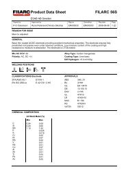
Pos: 5.1 /Überschriften/1.1/Plasmaschneiden als Verfahren @ 0\mod_1197554221573_6.doc @ 1702Pos: 5.2 /Allgemeines/Plasmaschneiden als Verfahren @ 0\mod_1198075619387_6.doc @ 2246Pos: 5.5 /Überschriften/1.1.1/Trocken-Plasmaschneiden @ 0\mod_1197554596042_6.doc @ 1710Pos: 5.6 /Überschriften/1.1.1.1/Trocken-Plasmaschneiden ohne Sekundärmedium @ 0\mod_1197554835210_6.doc @ 1718Pos: 5.7 /Allgemeines/Trockenplasmaschneiden ohne Sekundärmedium @ 0\mod_1199708913662_6.doc @ 2352Pos: 5.8 /Allgemeines/Prinzipdarstellung Plasmaschneiden ohne Sekundärmedium @ 0\mod_1199709444902_6.doc @ 2356Pos: 5.9 /Allgemeines/sichere Zündung des Pilotbogens @ 0\mod_1199709819725_6.doc @ 2360Pos: 5.10 /Warnung, Vorsicht, Verbot, Gebot, Hinweis/Verbotszeichen (rot)/ungeeignete Werkzeuge @ 0\mod_1199710363915_19.doc @ 2366Pos: 5.11 /Allgemeines/sichere Ausbildung des Hauptbogens @ 0\mod_1199710526238_19.doc @ 23701.4 Principle of dry plasma cutting without swirl gas1 Pilot resistor2 HV- igniter3 gas supply4 Cathode5 Nozzle6 Plasma arc (main arc)7 Workpiece8 Workpiece cableFig. 1: Principle of dry plasma cutting without swirl gasA safe ignition of the pilot arc is granted when following subsequent points:• The required parameters in regard to gas pressure and mains voltage must be observed.• The proper mounting of the consumables (Use the special tools according to the scope of delivery.)• The cathode must always be firmly tightened• The nozzle end must always be kept clean of dirt, especially of metal spatter. A soft wire brush can be usedfor cleaning.• If a plasma torch is available, then the central connector of the plasma hand torch must be tightenedto the limit stopUnder no circumstances pliers or other unsuitable tools have to be used for consumablechange, they entail inevitably the damage of the consumables, for example burr formationand thereby malfunctions of the plasma torch.7
Pos: 7.1 /Überschriften/1/Sicherheit @ 0\mod_1197388764940_6.doc @ 1437Pos: 7.2 /Überschriften/1.1/Erläuterung der Sicherheitssymbole @ 0\mod_1197465551735_6.doc @ 15352 Safety instructions2.1 Explanation of the safety symbolsPos: 7.3 /Sicherheit/Erläuterung der Symbole @ 0\mod_1197465063600_6.doc @ 1531DANGER, WARNING and CAUTION are signal words, which describes a degree of exposure.DANGERDANGER describes an endangerment with a high degree of risk, when it is not avoided, itresults in death or a severe injury.WARNINGWARNING describes an endangerment with a middle degree of risk, when it is not avoided, itcould result in death or a severe injury.CAUTIONCAUTION describes an endangerment with a low degree of risk, when it is not avoided, it couldresult in a slight or a moderate injury.The Safety information are developed after the SAFE-structure:S … Symbol with signal wordCAUTIONA … Art und Quelle der Restgefahr - Kind and source of the residual dangerF … Folge bei Missachtung - Consequence at ignoringE … Entkommen - EscapeExample:CAUTIONEndangerment through free standing wheels by <strong>manual</strong> moving of the unit.Foot injuries are possible.Caution by the <strong>manual</strong> moving of the unit - wear food guards!WARNINGWarning of dangerous electric voltageElectric shock can be deadly. Further personal and material damages can result fromimpact.Before opening (for example error search) or starting any maintenance and repair workprincipally the power supply source has to be switched off and visibly disconnected fromthe mains.Opening the plasma unit may be carried out only under responsibility of a qualifiedelectrician!8
Warning symbols (choice):A black graphic symbol within a yellow triangle with a black edge defines a safety sign,which describes an endangerment.Warning of general hazard areaWarning of dangerous electrical voltage!Warning of flammable substancesWarning of explosive substancesWarning of poisonous substancesWarning of optical radiationWarning of electromagnetic radiationWarning of noxious or irritant substancesWarning of gas cylinderWarning of hot surfaceWarning of slip danger9
Mandatory sign (choice):A white graphic symbol within a blue circle defines a safety sign, which indicates that anaction shall be carried out, in order to prevent an endangerment.General mandatory signUse eye shieldUse ear protectionUse inhalation protectionUse foot guardUse hand guardUse protective clothingBefore opening disconnect the mains plugConsider instruction <strong>manual</strong>Pressure gas cylinder locked by linkage10
Pos: 7.4 /--------------- Seitenumbruch --------------- @ 0\mod_1197390577023_6.doc @ 1452Prohibition sign (choice):A black graphic symbol within a red circle with a red diagonal bar defines a safety sign,which indicates that an action shall be stopped or not be carried out.Smoking is forbiddenFire, open light and smoking are forbiddenContact is forbiddenMeal and drinking are forbiddenDo not use in housing areasEmergency sign (choice):First aidFire protection sign (choice):Fire extinguisherInformation is not a signal word that describes a degree of exposure.InformationThe symbol signalised hints or special useful information.11
Pos: 7.5 /Sicherheit/Warnschild, Text @ 0\mod_1199715950375_6.doc @ 2402Pos: 7.6 /Sicherheit/Warnschild, Bild und Beschreibung @ 0\mod_1199716068148_6.doc @ 2406Pos: 7.8 /Sicherheit/Weitere Hinweise und Warnungen @ 0\mod_1199797455150_6.doc @ 2418Pos: 7.9 /--------------- Seitenumbruch --------------- @ 0\mod_1197390577023_6.doc @ 1452Information and warning:1. The operator and the maintenance personnel must read and understand the instruction <strong>manual</strong> aswell as learning the operation of the unit before work with it to avoid endangerments.The safety regulations of the respective company have to be taken into account.2. Smoke, dust and gases developed during the cutting process are harmful for health and may not bebreathed in. Principally a suitable fume extraction device has to be used.3. Wearing of protective clothing (helmet, welder’s overall, leather apron, gauntlets, safety shoes). Theprotective clothing has to be isolating, dry and heavily inflammable4. Noise can damage the hearing! During the plasma cutting operation suitable ear protection has to beused. The radiation of the plasma arc can lead to eye injuries and skin burns. Eyes and skin have tobe protected from the radiation of the plasma arc therefore. Protection devices are safety gogglesandhand shields, which must have a sufficient lens shade.5. Electric shock can kill! Live electrical parts may not be touched.Opening the plasma unit may be carried out only by an advised electrician. Before carrying out anymaintenance or repair work the unit has to be disconnected visibly from the mains!6. Wearing of protective clothing (helmet, welder’s overall, leather apron, gauntlets, safety shoes). Theprotective clothing has to be isolating, dry and heavily inflammable. Working with plasma cuttingmachines possibly can lead to fire and explosions. Flammable and explosive materials musttherefore be kept away from the cutting area. It has to be ensured that suitable and easily accessibleextinguishing facilities are located nearby. The appropriate fire protection regulations have to betaken into account.7. Appropriate warning labels may not be removed, painted over or covered.• to ensure stableness of the plasma unit, an inclination of 10° may not be exceeded• connect the power source only with properly fitted protective conductor.• place the torch on an insulated place, to protect the operator against workpiece and ground potential• keep dry the working area and all parts of the unit• don’t start the unit if components or parts are defective• the plasma cutting machine has to be earthed and connected to the workpiece before switching on!• switch off the unit before touching the plasma torch and prevent accidental restart• arrange regular electric inspections (by an authorized electronics engineer)• keep doors and flaps closed as long as the unit is connected to the power supply• never avoid or suspend the safety interlock (for example door-, gas nozzle- and protection cap safetyswitch)• do not cut closed containers• The plasma cutting machine may be used only for the appointed use. It may not be used e.g. to defrostfrozen pipes.• Do not touch the torch head, the workpiece or the water (if water table is used) when the plasma unit isworking.• Inflammable objects (e.g. lighters, matchsticks) may not be carried by the operator at the body.• it can come to injuries caused by contacting sharp edges of the workpiece12
Pos: 7.10 /Überschriften/1.1/Gefährdung durch hohe Berührungsspannung @ 0\mod_1197552041125_6.doc @ 1658Pos: 7.11 /Warnung, Vorsicht, Verbot, Gebot, Hinweis/Warnung (orange) / Rettungszeichen (grün)/Warnung Öffnen des Gerätes @ 0\mod_1199714392778_6.doc @ 2389Pos: 7.12 /Sicherheit/Werkstück anschließen und erden @ 0\mod_1200052757236_6.doc @ 2728Pos: 7.13 /Überschriften/1.1/Arbeit in Umgebungen mit erhöhter elektrischer Gefährdung @ 0\mod_1197552194054_6.doc @ 1662Pos: 7.14 /Sicherheit/Arbeit unter erhöhter elektrischer Gefährdung @ 0\mod_1199797937814_6.doc @ 2422Pos: 7.15 /Warnung, Vorsicht, Verbot, Gebot, Hinweis/Gebotszeichen (blau)/geltende nationale und lokale Vorschriften @ 0\mod_1199802901541_19.doc @ 2505Pos: 7.16 /--------------- Seitenumbruch --------------- @ 0\mod_1197390577023_6.doc @ 14522.2 Endangerment by high contact voltageWARNINGWarning of dangerous electric voltageElectric shock can be deadly. Further personal and material damages can result fromimpact.Before opening (for example error search) or starting any maintenance and repair workprincipally the power supply source has to be switched off and visibly disconnected fromthe mains.Opening the plasma unit may be carried out only under responsibility of a qualifiedelectrician!WARNINGElectric shock through touching of the torch head, if the plasma unit is switched on.Electric shock can be deadly. Further personal and material damages can result fromimpact.Never touch the torch head, if the power source is switched on!Before starting the machine connect the workpiece cable and earth the workpiece!WARNINGWarning of electromagnetic interferencesThrough the operation of the plasma cutting machine in particular by the temporary highvoltage ignition procedure results electromagnetic fields, which can lead to the influencingof a medical equipment (e.g. cardiac pacemakers, hearing aids, insulin pumps) and bodyimplants.Persons concerned must consult their specialist before beginning of work at plasmacutting machines!2.3 Working in environments with increased electric endangermentThe plasma cutting machine is built in compliance with valid standards EN 60974-1 and therefore applicablein environments with increased hazard of electric shock.The conditions for fulfilling these requirements are given by design measures in the plasma cutting machine:• The plasma power source and the plasma torch are forming a safety-proofed installation, which can beseparated only by a tool (as far as a central connector with mechanical locking is present).The unit cannotbe switched on as long no torch is attached or the attached torch isn't assembled completely.• Opening the control circuit effects switching off the open circuit voltage, which drops down within theprescribed time below the limit• Cutting with hand torch is only possible with mounted, electrically insulating protection cap, whichprotects against accidental touching the live nozzle cap. If the protection cap is not available the torch cannot switched on (security circuit).Therefore the plasma cutting unit is S-marked and applicable in environments with increased hazard toelectric shock.The operator has to follow national and local regulations (for example Employer’s LiabilityInsurance Association)!13
Pos: 7.17 /Überschriften/1.1/Gefährdung durch Hochspannungszündung @ 0\mod_1197552347357_6.doc @ 1666Pos: 7.19 /Warnung, Vorsicht, Verbot, Gebot, Hinweis/Warnung (orange) / Rettungszeichen (grün)/Brennerkopf nicht berühren @ 0\mod_1202996840384_6.doc @ 3674Pos: 7.22 /Überschriften/1.1/Gefährdung durch elektromagnetische Störungen @ 0\mod_1197552428045_6.doc @ 1670Pos: 7.23 /Sicherheit/Gefährdung durch elektromagnetische Störungen-Teil1 @ 0\mod_1199798656080_6.doc @ 2434Pos: 7.23 /Sicherheit/Gefährdung durch elektromagnetische Störungen-Teil1 @ 0\mod_1199798656080_19.doc @ 2436Pos: 7.24 /Warnung, Vorsicht, Verbot, Gebot, Hinweis/Warnung (orange) / Rettungszeichen (grün)/Warnung vor elektromagnetischer Strahlung @ 0\mod_1216038037393_19.doc @ 4620Pos: 7.25 /Warnung, Vorsicht, Verbot, Gebot, Hinweis/Warnung (orange) / Rettungszeichen (grün)/nicht für den Gebrauch in Wohnbereichen @ 1\mod_1225968019851_19.doc @ 5650Pos: 7.26 /Sicherheit/Gefährdung durch elektromagnetische Störungen-Teil2 @ 0\mod_1199798737806_19.doc @ 2440Pos: 7.27 /Sicherheit/Gefährdung durch elektromagnetische Störungen-Teil3 @ 0\mod_1199798845546_19.doc @ 2444Pos: 7.28 /--------------- Seitenumbruch --------------- @ 0\mod_1197390577023_6.doc @ 14522.4 Endangerment by electromagnetic fieldsThe plasma cutting installation complies with the instructions of the EN 60974-10 (VDE 0544, part 10) "ArcWelding Equipment – part 10: requirements at the Electromagnetic Compatibility (EMC)". This standard isvalid for Arc Welding Installations and related processes (e.g. plasma cutting).WARNINGWarning of electromagnetic interferencesThrough the operation of the plasma cutting machine in particular by the temporary highvoltage ignition procedure results electromagnetic fields, which can lead to the influencingof a medical equipment (e.g. cardiac pacemakers, hearing aids, insulin pumps) and bodyimplants.Persons concerned must consult their specialist before beginning of work at plasmacutting machines!WARNINGThe plasma cutting unit is an attachment of the class A according to EMC classification toCISPR11:This class A cutting mechanism is not intended for the use in living quarters, in which thecurrent supply is made by a public low-voltage utility system. It can be possibly difficult,both by line-bound and radiated disturbances, to ensure within these rangeselectromagnetic compatibility.GeneralThe user is responsible for installing and using the installation according to the manufacturer’s instruction. Ifelectromagnetic disturbances are detected then the user is responsible to arrange the technical solution withthe assistance of the manufacturer.Recommendations for assessment of the area (EN 60974-10)Before installing the equipment the user shall make an assessment of potential electromagnetic problems inthe surrounding area, and shall take the following into account:• Other supply cables, control cables, signalling and telephone cables; below and adjacent to the installation• Radio and television transmitters and receivers• Computer and other control equipment• Safety devices, e.g. protections for industrial equipment• Health of the people around, wearing pacemakers or hearing aids and other body implants• Equipment for calibration and measuring• Immunity of other equipment in the environment. The user shall ensure that other additional protectionmeasures in the environment are compatible• Time of day that cutting has to be carried out.The size of the observed surrounding area depends on the design of the building and other activities takingplace there. The range can extend over the property boundary.14
Pos: 7.29 /Sicherheit/Gefährdung durch elektromagnetische Störungen-Teil4 @ 0\mod_1199799007142_6.doc @ 2446Pos: 7.30 /Warnung, Vorsicht, Verbot, Gebot, Hinweis/Gebotszeichen (blau)/geltende nationale und lokale Vorschriften @ 0\mod_1199802901541_19.doc @ 2505Pos: 7.31 /Überschriften/1.1/Gefährdung durch Wärme- und Lichtstrahlung @ 0\mod_1197552537506_6.doc @ 1674Pos: 7.32 /Sicherheit/Gefährdung durch Wärme-und Lichtstrahlung @ 0\mod_1199799546328_6.doc @ 2450Pos: 7.33 /Warnung, Vorsicht, Verbot, Gebot, Hinweis/Gebotszeichen (blau)/geltende nationale und lokale Vorschriften @ 0\mod_1199802901541_19.doc @ 2505Pos: 7.34 /--------------- Seitenumbruch --------------- @ 0\mod_1197390577023_6.doc @ 1452Recommendations of methods to minimize disturbancesIf disturbances are detected it may be necessary to carry out further precautions, such as those:• Filtering of the mains supply• Shielding the mains cable of the permanently installed plasma cutting (safe contact is necessary betweenshielding and housing)• Regular maintenance of the plasma cutting installation• All cover plates, service openings and flaps have to be closed before starting the unit• No alternations on adjustments and settings should be done at the plasma unit whitout the acceptance ofthe producer• Cutting cables should be kept as short as possible and closely together or take course close to the bottom• Potential equalization of all metallic components should be considered inside and adjacent to theinstallation. The operator should be insulated from all metallic components.• Earthing of the workpiece• Selective screening of all other cables and equipmentThe operator has to follow national and local regulations (for example Employer’s LiabilityInsurance Association)!2.6 Endangerment by heat and light radiationThe radiation of the plasma arc can lead to eye injuries and skin burns. Eyes and skin have to be protectedfrom the radiation of the plasma arc therefore..Safety measures:• Wearing of total protective clothing (helmet, welding overall, possibly apron, gauntlet gloves, safetyshoes).The protective clothing has to be insulated, dry and flame-resistant.• Protection devices are safety goggles and hand shields, which must have a sufficient lens shade.• The cutting area should be prepared so that reflections and transmission of ultraviolet light is reduced:− use of protective walls− arranging painting of walls with dark colourThe operator has to follow national and local regulations (for example Employer’s LiabilityInsurance Association)!15
Pos: 7.35 /Überschriften/1.1/Gefährdung durch Gase, Rauche und Stäube @ 0\mod_1197552640467_6.doc @ 1678Pos: 7.36 /Sicherheit/Gefährdung durch Gase, Rauche und Stäube @ 0\mod_1199799715379_6.doc @ 2454Pos: 7.36 /Sicherheit/Gefährdung durch Gase, Rauche und Stäube @ 0\mod_1199799715379_19.doc @ 2456Pos: 7.37 /Warnung, Vorsicht, Verbot, Gebot, Hinweis/Gebotszeichen (blau)/gesundheitsschädliche Stoffe @ 0\mod_1199803444549_19.doc @ 2517Pos: 7.38 /Warnung, Vorsicht, Verbot, Gebot, Hinweis/Warnung (orange) / Rettungszeichen (grün)/Atemmaske tragen @ 0\mod_1216121028627_19.doc @ 4630Pos: 7.39 /Warnung, Vorsicht, Verbot, Gebot, Hinweis/Gebotszeichen (blau)/geltende nationale und lokale Vorschriften @ 0\mod_1199802901541_19.doc @ 2505Pos: 7.40 /Überschriften/1.1/Vermeidung von Knallgasbildung @ 0\mod_1197552737646_6.doc @ 1682Pos: 7.41 /Sicherheit/Vermeidung von Knallgasbildung-Teil1 @ 0\mod_1199799928396_6.doc @ 2458Pos: 7.41 /Sicherheit/Vermeidung von Knallgasbildung-Teil1 @ 0\mod_1199799928396_19.doc @ 2460Pos: 7.42 /Warnung, Vorsicht, Verbot, Gebot, Hinweis/Warnung (orange) / Rettungszeichen (grün)/Knallgasbildung @ 0\mod_1199803553943_19.doc @ 2521Pos: 7.43 /--------------- Seitenumbruch --------------- @ 0\mod_1197390577023_6.doc @ 14522.7 Endangerments by gases, smoke and types of dustDue to the plasma process itself hazardous substances may be produced. To avoid risks on health thefollowing has to be arranged:• Keep cutting place well ventilated• Remove fumes, smoke and dust by exhaustion devices• Removed all chlorinated and other solvents from the cutting area because they could form phosgene gaswhen exposed to ultraviolet radiation• Ensure that toxic limits become not exceededIn any case the user of the plasma cutting installation has to carry out measurements ofthe concentration of toxic substances to proof the effectiveness of the exhaust equipment!WARNINGDanger by gases and smokes when cutting galvanized material health damage byinhalation that gases and smokes.Carry special breathing mask when cutting galvanized material!The operator has to follow national and local regulations (for example Employer’s LiabilityInsurance Association)!2.8 Measures for prevention of "Oxyhydrogen gas formation"(Does only apply for plasma cutting of aluminium in any combination with water)The molten aluminium which is blown out of the cutting kerf forms in water an aluminium granule which isoxidizing in water very fast because of its large surface.Hydrogen is generated due to the bond of oxygen of the water. The hydrogen raises in the water table to thesurface, is ignited during the cutting process and burns out (reddish flame).This reductive process can last for days in the slag of the water cutting table. Mainly compressed air is usedfor the automatic level control of the water table, and by that a hydrogen-air mixture will be generated, thatexplosively reacts in a hydrogen share between 4 and 76 Vol% (oxyhydrogen gas), if it is ignited by theplasma arc.WARNINGDanger of the formation of highly explosive oxyhydrogen- at hollow spaces,- at the displacing chamber of the water cutting table and- below the tin plate lying on the cutting table.There is danger of injury by exploding oxyhydrogen and around flying parts.The following information have to be observed to avoid the danger!16
Pos: 7.44 /Sicherheit/Vermeidung von Knallgasbildung-Teil2 @ 0\mod_1199800260679_6.doc @ 2467Pos: 7.45 /Warnung, Vorsicht, Verbot, Gebot, Hinweis/Verbotszeichen (rot)/Lagern von Blechtafeln @ 0\mod_1199803631629_19.doc @ 2525: 7.46 /--------------- Seitenumbruch --------------- @ 0\mod_1197390577023_6.doc @ 1452Pos: 7.47 /Überschriften/1.1/Gefährdung durch Lärm @ 0\mod_1197552995672_6.doc @ 1686Pos: 7.48 /Sicherheit/Gefährdung durch Lärm-Teil1 @ 0\mod_1199800350921_6.doc @ 2471Pos: 7.48 /Sicherheit/Gefährdung durch Lärm-Teil1 @ 0\mod_1199800350921_19.doc @ 2473Pos: 7.49 /Sicherheit/CutFire-Schallpegelmessung @ 1\mod_1233227633612_6.doc @ 8107Pos: 7.51 /Warnung, Vorsicht, Verbot, Gebot, Hinweis/Gebotszeichen (blau)/geltende nationale und lokale Vorschriften @ 0\mod_1199802901541_19.doc @ 2505Pos: 7.52 /--------------- Seitenumbruch --------------- @ 0\mod_1197390577023_6.doc @ 1452For water tables with level control Nitrogen has to be used instead of air for cutting of aluminium.Nitrogen with small purity is here sufficient.For water tables without level control it has to be ensured, that:• hydrogen can escape freely everywhere and is burnt out• the inside contour of the water table is even so that no granule can gather at inaccessible spaces• the slag and the granule are removed from the water table without delay• the guiding machine has to be positioned after the cutting outside the water table to avoid, that hydrogen oroxyhydrogen (hydrogen-air mixture) can gather in hollow spaces (like switch boxes)• that no hydrogen can gather below the plate which is placed on the table gratingIt is not allowed to store the plates on the cutting grating for a longer time!2.9 Endangerment by noiseBe aware that during the plasma cutting a high noise level is produced.Depending on the technological process and the cutting parameters in a meter distance from the pilot arc thefollowing sound level is reached:Process: Dry plasma cuttingcuttingcurrent(A)materialthickness(mm)max. sound levelwith a height of:1 m 3 m 6 mmeasuredcalculatedmaterialcutting pressure(bar)/nozzlein db(A) in db(A) in db(A)35 3,0 93 83 78 mild steel 4,0 (0,8)Fig. 2: sound-level with dry plasma cutting processSuitable ear protection measures have to be taken in every case(e.g. wearing of ear muffs or ear plugs)!The operator has to follow national and local regulations (for example Employer’s LiabilityInsurance Association)!17
Pos: 7.53 /Überschriften/1.1/Gefährdung durch Schneidspritzer @ 0\mod_1197553139562_6.doc @ 1690Pos: 7.54 /Sicherheit/Gefährdung durch Schneidspritzer @ 0\mod_1199800700797_6.doc @ 2479Pos: 7.54 /Sicherheit/Gefährdung durch Schneidspritzer @ 0\mod_1199800700797_19.doc @ 2481Pos: 7.55 /Überschriften/1.1/Umgang mit Gasflaschen @ 0\mod_1197553579259_6.doc @ 1694Pos: 7.56 /Warnung, Vorsicht, Verbot, Gebot, Hinweis/Gebotszeichen (blau)/Gasversorgung- Druckminderer @ 0\mod_1199803733989_19.doc @ 2529Pos: 7.57 /Warnung, Vorsicht, Verbot, Gebot, Hinweis/Gebotszeichen (blau)/geltende nationale und lokale Vorschriften @ 0\mod_1199802901541_19.doc @ 2505Pos: 7.58 /Sicherheit/Umgang mit Gasflaschen @ 0\mod_1199800822668_19.doc @ 2485Pos: 8 /--------------- Seitenumbruch --------------- @ 0\mod_1197390577023_6.doc @ 14522.10 Endangerment by spatterDuring plasma cutting and hole piercing sparks, slag and hot metal are produced. The risk of burns and fireexists!To avoid endangerments the following has to be arranged:• removal of all potential flammable materials from the cutting area, at least in a distance of 10 m• cool down freshly cut material before handling or storing• make fire extinguishers available in the cutting area2.11 Handling of pressure reducerFor the gas supply only high- quality, preferable two- step pressure regulators have to beused, guaranteeing a constant supply pressure. The quality of the pressure reducerinfluences the cutting quality and reliability of the complete unit. Pressure reducers thatare conform to the quality requirements are mentioned in the order specifications ofKjellberg. Furthermore the user has to follow local and national standards.The operator has to follow national and local regulations (for example Employer’s LiabilityInsurance Association)!WARNINGFor the plasma cutting process compressed gases are used.To avoid endangerments following instructions have to be taken:• please cylinders upright in secured position• don't use damaged cylinders, pressure reducers and armatures• only employ the pressure reducer for corresponding gas• never lubricate pressure reducers with grease and oil• all parts, which coming into contact with oxygen, must be absolutely free of oil and grease• when using oxygen the pressure reducer must be furnished with an explosion protection(Protection before flame setbacks)• perform gas pressure test acc. to chapter "Gas pressure test"18
Pos: 9.1 /Überschriften/1/Wartung @ 0\mod_1197550754735_6.doc @ 1638Pos: 9.2 /Warnung, Vorsicht, Verbot, Gebot, Hinweis/Warnung (orange) / Rettungszeichen (grün)/Warnung Öffnen des Gerätes @ 0\mod_1199714392778_19.doc @ 2391Pos: 9.3 /Überschriften/1.1/Wartung allgemein @ 0\mod_1197555563715_6.doc @ 1726Pos: 9.4 /Überschriften/1.1.1/Wartungsintervalle @ 0\mod_1197629873017_6.doc @ 1758Pos: 9.5 /Wartung/Wartungsintervalle @ 0\mod_1197989815561_19.doc @ 2130Pos: 9.6 /--------------- Seitenumbruch --------------- @ 0\mod_1197390577023_6.doc @ 14523 MaintenanceWARNINGWarning of dangerous electric voltageElectric shock can be deadly. Further personal and material damages can result from impact.Before opening (for example error search) or starting any maintenance and repair workprincipally the power supply source has to be switched off and visibly disconnected from themains.Opening the plasma unit may be carried out only under responsibility of a qualifiedelectrician!3.1 Maintenance general3.1.1 Intervals of maintenanceFollowing measures have to be taken in regular intervals:Maintenance rateweeklymonthlyall 4 to 6 monthMaintenance work- visual inspection of the condition of the plasma powersource, all system components and the plasma torches- control of the filling level of the coolant (fill up on demand)- inspection of the service units or fine filter for the gassupply on cleanliness(discharge resulted condensation)by application of Hydrogen or Oxygen:inspection of the gas supply(see chapter gas pressure test)- Cleaning the power source and all components(control of the filter pads)- Cleaning small filters inside the gas connectors of thePlasma Gas Control UnitsTarget groupOperatorxxauthorizedelectricalpersonalall 6 month electrical revision xyearlyfor liquid cooled units:complete change of coolant „Kjellfrost“xxx19
Pos: 9.7 /Überschriften/1.1.1/Reinigung @ 0\mod_1197630016183_6.doc @ 1762Pos: 9.9 /Wartung/Reinigung der Stromquelle @ 0\mod_1197990338325_19.doc @ 2134Gleichermaßen sind installierte Plasmakomponenten zu reinigen.Pos: 9.13 /Überschriften/1.1.1/elektrische Revision @ 0\mod_1197630324394_6.doc @ 1766Pos: 9.14 /Warnung, Vorsicht, Verbot, Gebot, Hinweis/Gebotszeichen (blau)/elektrische Revision durch Elektrofachkraft @ 0\mod_1215496817737_6.doc @ 4469Pos: 9.15 /Wartung/Elektrische Revision @ 0\mod_1197990462046_6.doc @ 2136Pos: 9.16 /--------------- Seitenumbruch --------------- @ 0\mod_1197390577023_6.doc @ 14523.1.2 Cleaning of the power sourceFrom the power source all dust and dirt which has collected inside by the fan have to be removed in intervalsof 4 to 6 months. Blowing out should be done carefully with dry compressed air, more effective is to use avacuum cleaner.When working in shifts or under unfavourable conditions the regular cleaning should take place inshorter intervalls.For ensuring an effective cooling filter mattes, if existing, should be cleaned in water (approx. 40°C)by using standard detergents.Manual cleaning is useful as well (beating; exhausting; with compressed air, e.g.)3.1.3 Electrical revisionThe electrical revision of the plasma cutting machine and the disposal of the noticeddefects have to be carried out according to the statutory regulations via electricalspecialist!A repeated inspection has to be carried out in electrical installations and equipment inregular time intervals. These have to be executed according to DIN EN 60974-4"Arc welding equipment - in-service inspection and testing."The operator has to follow national and local regulations (for example Employer’s LiabilityInsurance Association)!The operations to be undertaken for inspection and testing are:a) visual inspectionb) electrical inspection• open circuit voltage• insulating resistance• protection conductor resistance• documentationManufacturer's instructions to measure the open circuit voltage1. connect the plasma torch2. connect the measurements between cathode and workpiece3. connect mains voltage4. switch ON the CUTi5. press the push-button of the torch6. measure the voltage between cathode and workpieceManufacturer's instructions to check the insulation values:1. switch On the mains switch2. connect the workpiece connection and the torch connection (middle contact/cathode) with eachother3. connect all 3 phases at the mains input4. measure insulation values at a cold and dry condition between mains input and housing5. measure insulation values at a cold and dry condition between torch connection (middle contact /cathode) -/workpiece connection and housing6. measure insulation values at a cold and dry condition between mains input and torch connection(middle contact / cathode) -/workpiece connection20
Pos: 9.17 /Überschriften/1.1.1/Plasmabrenner @ 0\mod_1197630447123_6.doc @ 1770Pos: 9.18 /Wartung/Plasmabrenner @ 0\mod_1199372283358_19.doc @ 2284Pos: 9.19 /Warnung, Vorsicht, Verbot, Gebot, Hinweis/Warnung (orange) / Rettungszeichen (grün)/Öl-und fettfreier Brenner @ 0\mod_1199373195000_19.doc @ 2300Pos: 9.20 /Warnung, Vorsicht, Verbot, Gebot, Hinweis/Gebotszeichen (blau)/Original-Kjellberg-Verschleißteile @ 0\mod_1202913276255_19.doc @ 3649Pos: 10 /--------------- Seitenumbruch --------------- @ 0\mod_1197390577023_6.doc @ 14523.1.4 Plasma torchThe plasma torches have to be handled with care. Powerful treatment and stress load have to be avoided.All consumables have to be in clean condition and carefully changed in time (see instruction <strong>manual</strong> of thePlasma Machine Torch).Damages of parts inside the torch, like nozzle holder and cathode tube have to be avoided.Besides the change of consumables by using the special torch tools no other action to the torchhead is allowed! Plasma torches must be transported and stored at protected places with full inserted partson the torch head only!Hose parcels have to be protected against damages, like sharp bending, twisting, over rolling, and thermaldamages as well. The cleanness of the small filters in the gas connections has to be checked regularly at theplasma machine torch. The small filter is to be screwed in with the thread forward into the connection of therespective gas hoseWARNINGAll components and parts coming in touch with oxygen have to be kept free of oil andgrease!This refers specially to the torch head and the consumables.You are only allowed to use ORIGINAL Kjellberg spare parts and consumables!The use of other manufacturer consumables leads to the loss of the warranty claim.21
Pos: 11.1 /Überschriften/1/Entsorgung @ 0\mod_1214904396582_6.doc @ 4393Pos: 11.2 /Überschriften/1.1/Entsorgung des Verpackungsmaterials @ 0\mod_1215004453711_6.doc @ 4425Pos: 11.3 /Entsorgung/Entsorgung des Verpackungsmaterials @ 0\mod_1215004684976_6.doc @ 4430Pos: 11.4 /Überschriften/1.1/Entsorgung der Geräte @ 0\mod_1215004248209_6.doc @ 4420Pos: 12 /--------------- Seitenumbruch --------------- @ 0\mod_1197390577023_6.doc @ 1454 Disposal4.1 Disposal of the packing materialplasma unitplasma components and accessoriesconsumablespacking materialwooden pallet or solid wooden boxwooden palletplastic box (package and keeping)If packing materials are not needed for repacking or for a possibly necessary storage of the units betweenintervals of normal use, the materials can properly be recycled and disposed on the basis of regionalapplicable regulations by a waste management company.4.2 Disposal of the unitsPos: 11.5 /Entsorgung/Entsorgung der Geräte @ 0\mod_1214904040990_19.doc @ 4389The units of the company Kjellberg Finsterwalde are products which can properly be recycled and disposedafter placing out of operation on the basis of regional applicable regulations by a waste managementcompany.22
5 Power source CUTi 35C5.1 Technical dataCUTi 35Cprimary side:input voltage U 1 :max. connecting load S 1 :1 x 230 V +10/-10% 50/60 Hz3,3 / 4,8 kVApower factor cos phi: 0,71efficiency: 0,91main connection :fuse, slow [A]16cross section, Cu [mm²] 3 x 1,5cutting sideopen circuit voltage U 0 :cutting current I S :• with internal compressor• with external air pressureCutting voltage U S :Duty cycle *:max. thickness d s(external air pressure supply):max. thickness d s(with internal compressor):characteristic:ignition process:workpiece cable:weight:dimensions (lxbxh):protection class:cooling:Torch cooling:at external air pressure supply:pressure:flow rate:plasma gascooling gasconnection:270 V DC12 - 25 A12 - 35 A85 - 94 V DC25% at 35 A35% at 25A100% at 20 A10 mm6 mmdroopingpilot arc ignition by high voltage ignition unit;main arc ignition by pilot arc10 mm 212,5 kg550 x 150 x 245 mmIP 23Air cooled by built-in fangas coolingAir, free of oil and water0.4 MPa (4 bar)115 l/minhose fittings for hose inside Ø 6 mm* The duty cycle characterises a load-time calculation within a period of 10 min.Example: Duty cycle =25 % means that the indicated cutting current can demand 2.5 minutes from thedevice, whereupon a cooling phase follows for the remaining 7.5 min.Fig. 3: Technical data23
5.2 Technical descriptionOnly plasma torches of the type PHT-25 G/L of Kjellberg Finsterwalde are determined foruse with power sources CUTi 35C by EN 60974-1.Exclusive these plasma torches forms a safety-related unit with the named power sourcesin accordance with EN 60974-7!The following components are required at minimum for the cutting of electrically conductive materials withthe plasma cutting unit CUTi 35C:• plasma cutting inverter CUTi 35C with filter pressure reducer• plasma hand torch PHT-25 G/L with the according consumables and tools• workpiece cableAll modules of the CUTi 35C are placed in a portable housing. The control and display elements are placedat the front panel.The rear panel contains the connection for the workpiece cable connection, the plasma gas connection withthe filter pressure reducer and the insertion of the main cable.The gas supply consists of the gas connector with filter pressure reducer, the solenoid valve and thepressure switch, which switches off the plasma cutting unit in case the pressure drops below 0.3MPa.All power components are protected against thermal overload by means of a thermal switch.5.3 Main features and advantagesDue to the extreme high energy density a number of technical advantages will be obtained::• narrow cutting kerfs• low loss of material• low heat input• Small distortion• high cutting speed• good cutting quality• recommended material-dependent range of material thickness from 6 mm (internal compressor, max. 25A)or 10 mm max. (separating cut, with an external air pressure supply) at a maximum cutting power of 35 A• control installations guarantee safe functioning:- gas pressure monitoring- temperature monitoring of the power components through thermal switch• ease-of-use through comprehensibly arranged control and display elements with symbols• modern industrial design, portable24
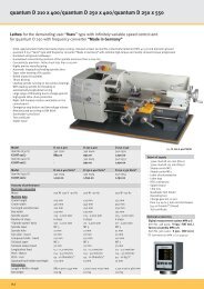
Pos: 13.26 /Stromquellen/CutFire/CutFire100i/Aufstellung @ 1\mod_1232435765086_19.doc @ 78985.4 Ranges of applicationMild steels, high-alloyed steels, nonferrous metals (e.g. aluminium), and special alloys can be cut. Air isused as plasma gas.The plasma torches can be used for flying cutting and hole piercing.Straight, bevel, contour, and position cuts can be carried out as well as fusion drilling. In this manner, semifinishedproducts such as sheet metal, pipes, profiles, metal blanks, forged and formed parts, sheet stacks,scrap products, and castings can be thermally separated or processed.Because of the continuously adjustable cutting current, the cutting power can be optimally adapted to thecutting task.5.5 Commissioning5.5.1 Transport, check, installation, storage, repack• Please check the delivery directly on the basis of the order and delivery documents on completeness andcorrectness. In the case of incompleteness or deviations please inform the supplier and the carrierimmediately.• Please check the delivery immediately on damages. Damages have to be announced immediately to thecarrier and supplier.A damage report has to be generated.The unit is designed for a service in explosion-proofed rooms or in the free air by using a roofing underfollowing conditions:• ambient temperature: -10 °C up to +40 °C• relative moisture: max. 90 % bei 20 °Cmax. 50 % bei 40 °CPlace the power source so that the air flow is not blocked. The unit is to be set up in such a way that thecooling air can enter and escape unhindered by the ventilation openings. A free distance of at least250 mm should be kept around all 4 sides of the unitThe Plasma Cutting Machine is designed acc. to the requirements of the protection class IP 21(DIN EN 60529), that means:• protection against penetration of solid parts above 12 mm size• protection against dripping waterThe unit has to be installed horizontally.25
5.5.2 InstallationWARNINGIt is not allowed to operate the machine with any of the housing cover plates not in place! Itis hazardous to the operator and other people in the area, and prevents the equipment fromproperly cooling the components! Generally the plasma cutting unit has to be switchedOFF and disconnected visibly from the mains (unplug supply cable) before opening anycover from the power source or from other components!5.5.2.1 Mains connectionThe CUTi 35C is equipped with a mains cable (3 x 1,5 mm 2 , 3 m long) and shock-proofed socket.The unit must be connected to the mains supply via a permanently installed socket. Mains fuses must beconnected in series up to the current socket according to the table “Technical Data of the Plasma cuttinginverter”. Connection to the mains supply must be carried out with the power source switched off.The plasma cutting inverter is suitable for operation at electric power generators, if the following minimumrequirements are met:• power output:mind. 10,0 kVA• max. voltage fluctuations at a rated load of: -10 % / +10 % with rapid change of load(arc ignition / arc interruption)5.5.2.2 Connection of the plasma torchFor the “Connection of the plasma torch” please refer to the service <strong>manual</strong> of the plasma torch !!!5.5.2.3 Workpiece connection / current return lineThe workpiece cable is connected to the welding cable socket on the rear panel. The workpiece clamp hasto be fastened firmly to the workpiece, component or equipment at which the cutting process is to be carriedout. Good contact must be established.WARNINGIt is not allowed to use conductive parts of building, like steel construction, pipes, trackways or similar devices for conducting the power back to the plasma cutting unit, as farcutting is not performed at those parts!26
5.5.2.4 Connection of gas supplyPlasma gas: Air (clean, oil, water and grease free)Gas pressure: 0.4 MPa (4 bar)Flow rate: 115 l/minWARNINGThe maximum input pressure may not exceed 0,7 MPa (7 bar)!Follow the conditions for using gas cylinders and the manufacturer's instructions ofpressure reducers!Using unclean gases can lead to dual arcs, increased wear of the nozzlesand cathodes, and damage the torch. The gas connection of the CUTi 35C isequipped with a filter pressure reducer to prevent soiling.1 Adjusting knob to adjust the pressure of the plasma gas- pull out unlock- turn clockwise pressure increase- turn the other way pressure decrease- push in arrest2 gas inlet3 gas outlet filter pressure reducer / gas inlet CUTi 35C4 manometer5 Condensate drain valve (semi-automatic, drainage is carried out withdepressurised filter pressure reducer.Fig. 4: filter pressure reducerGas supply using compressed air bottle:• Check cylinder valve to see if clean (free from oil and grease) and clean if necessary• Open the cylinder valve for a short time to blow out dust• Connect air pressure-reducer to cylinder• Connect pressure reducer to the filter pressure reducer with a gas hose• Open the valve, adjust the gas pressure at the pressure reducer to 0.5 to 0.6 MPa (5 to 6 bar)(control reserve for filter pressure reducer)• adjusting a pressure of 0.4 MPa (4 bar) at the filter pressure reducer at flowing gasGas supply using ring mains or compressor:• The use of an oil and water separator and a cold drier is necessary• It is to be connected between the ring mains and the filter pressure reducer• adjust the pressure to 0.6 MPa (6 bar) at the compressor• adjusting a pressure of 0.4 MPa (4 bar) at the filter pressure reducer at flowing gasWARNINGAn increase of gas pressure at the filter pressure reducer can degrade the ignition andcutting properties.27
5.5.3 Operation5.5.3.1 Control and display elementsFig. 5: control and display elements CUTi 35C (front panel)1 potentiometer “cutting current”adjust the cutting current to 15 - 25 A (internal compressor)15- 35A (external air pressure connection)The switchover of the maximum cutting current is carried out automatically.2 plasma torch3 workpiece cable4 LED signal lamp H1 green :- ON, mains voltage5 LED signal lamp H2 yellow:- LED on, when external air pressure is connected- at the same time the maximum cutting current is increased automatically to 35A6 LED signal lamp H3 yellow: temperature error- LED on, when the inverter is terminally overloaded (exceeded maximum duty cycle)- unit cooling by running fan7 filter pressure reducer8 main switch (at the rear panel)28
Switching ON the CUTi 35CBefore cutting, the following steps must be carried out:Inspection of the plasma hand torch• proper and undamaged condition• mounting of the consumables required for the process (see chapter “cutting operation“ and “consumablesand their exchange” at the instruction <strong>manual</strong> of the plasma hand torch)• proper condition of the Kjellberg consumablesInspection of the CUTi 35C• mandatory mains safeguard (see section “Mains connection”)• correct connection of the workpiece cable (see section “Connection of Gas Supply”)• functionality of the gas supply (see section “Protective installations”)Switching ONWARNINGImmediately after switching on, carry out the pressure setting of the filter pressure reducerto 0.4 MPA (4 bar) by flowing gas!• switch the mains switch (8) S1 at the front panel to position 1- fan ON- cooling air is discharged from the rear panel• green LED illuminated signal lamp H3 (4)• adjust potentiometer (1) to the desired cutting current5.5.3.3 Switching OFF the CUTi 35CBy switching the mains switch S1 on the front panel to position 0, the system is switched off. When theCUTi 35C is not in use for a longer period of time, it is to be visibly unplugged from the mains.5.6 Cutting operation(applications closer explained in the chapter “cutting operation“ of the plasma torch)WARNINGIt is not allowed to operate the machine with any of the housing cover plates not in place! Itis hazardous to the operator and other people in the area, and prevents the equipment fromproperly cooling the components! Generally the plasma cutting unit has to be switchedOFF and disconnected visibly from the mains (unplug supply cable) before opening anycover from the power source or from other components!The following applications and operations are possible:• cutting start and ignition of pilot arc• hole piercing• cutting with connecting cap• cutting with wheel guide• cutting with circular cutting attachment• cutting with long consumables29
5.7 Protective installationsThe plasma cutting inverter is switched OFF by the following installations• temperature monitoring in case of thermal overload of the inverterThe following protective installations protect the operator against high contact voltage:• Protection against accidentally touching the nozzle: The plasma hand torch can only be operated withthe protective cap screwed on5.8 Trouble shootingWARNINGWarning of dangerous electric voltageElectric shock can be deadly. Further personal and material damages can result fromimpact.Before opening (for example error search) or starting any maintenance and repair workprincipally the power supply source has to be switched off and visibly disconnected fromthe mains.Opening the plasma unit may be carried out only under responsibility of a qualifiedelectrician!If during the operation malfunctions are registered the cutting has to be stopped and the reason to be foundout.1. no full cutting power• workpiece is not connected• the adjusted current values for thicker materials are too low (readjust through a potentiometer)• wrong nozzle2. unit not ready for cutting, yellow LED signal lamp H3 (6) leuchtet, is on• the Inverter was thermally overload (maximum duty cycles exceeded)• cooling the CUTi through a running fan (do not switch OFF!)30
6 Plasma hand torch PHT-25 G/LThe plasma torch of the type PHT-25 G/L of Kjellberg Finsterwalde are determined for usewith power sources CUTi 35C by EN 60974-1.Only these Plasma torches and power sources are safety-related units in accordance withEN 60974-7!6.1 CommissioningBefore using the plasma torch, it must be checked whether the consumables for therespective method are inserted in the torch.WARNINGBefore starting any installation or maintenance work the power source has to be switchedoff and visibly disconnected from the mains(unplug mains cable)!Consumables are the cathode, nozzle, gas guide and the protection cap. The multiple wrench serves tomount the parts.The operating personal may change only consumables at the plasma torch!Repairs are only allowed by the service personal of the firm Kjellberg Finsterwalde andauthorised companies.You are only allowed to use ORIGINAL Kjellberg spare parts and consumables!The use of other manufacturer consumables leads to the loss of the warranty claim.6.2 Cutting operationWARNINGDo not level the plasma torch towards the eyes or other parts of the body! Do not touch thenozzle, because there is an electrical hazard by the high voltage ignition and a risk of burnsfrom the pilot arc!Avoid “flash burn” of the eyes by wearing safety glasses!The pilot arc can only be ignited if the protection cap is screwed on (safety circuit).31
6.2.1 Cutting start and ignition of pilot arcThe pilot arc is ignited by pressing the torch button after an initial flow of gas. The nozzle is put on directlyon the material to be cut.When the pilot arc touches the workpiece, the main arc is automatically started and cutting can begin. Theworkpiece is cut by guiding the torch as evenly as possible.The pilot and main arc go out when the torch button is released. At the end of the workpiece the main arcautomatically goes out.As this is a hand-held device, the quality of the cut is dependent in each case on the skill ofthe operator..6.2.2 Hole piercingWARNINGUpcoming hot material can lead to endangerments (risk of burns and fire)!For piercing the plasma torch can be directly placed on the workpiece with material thicknesses of up to3 mm.If the material is thicker than 3 mm, the plasma torch should be held at an angle and after the pilot arc isignited swayed into the workpiece. The molten material is thus blown out of the cutting joint in a better way,preventing the material from spraying to the nozzle.Fig. 6: hole piercing32
6.2.3 Cutting with wheel guideThe wheel guide facilitates to a considerable extent <strong>manual</strong> guidance of cutting by means of easy-runningwheels. The wheel guide is attached to the torch head to the limit stop and both hexagon sockets arefastened. The correct distance between torch head and workpiece is thus established. The adjustment ifnecessary is made by the dismantling of the lateral screws (hexagon socket and hexagon) and moving theheight of the wheel guidesFig. 7: cutting with wheel guide6.2.4 Cutting with circular cutting attachmentThe torch holder is attached to the torch head to the limit stop and fastened with the grub screw.With the compass rod, which can be detached from the holder, circular parts with a diameter of 100 to 1000mm can be cut.The torch head is rotatable in the holder.The tip of the compass can be shifted and arrestedFig. 8: cutting with circular cutting attachment.33
6.3 Consumables and their exchangeWARNINGIn order to change consumables, the plasma cutting machine shall be switched OFF andsecured against any accidental start. An unauthorised start-up is prevented by e.g. pullingout the key of the key-operated switch after switching off the plasma cutting unit!Under no circumstances pliers or other unsuitable tools have to be used for consumablechange, they entail inevitably the damage of the consumables, for example burr formationand thereby malfunctions of the plasma torch.The operator has to follow national and local regulations (for example Employer’s LiabilityInsurance Association)!Used or damaged consumables shall be replaced in due time.(Reference: visible change of the cutting quality)The life time of the cathode depends on the cutting time and the number of ignitions.The life time of the nozzle mainly depends on the cutting time, the number of ignitions and the handling ofthe torch (performing of hole piercing, upcoming spatter, etc.)Be sure that the consumables are suitable for the intended cutting procedure.Removal of consumables1. Screw off the protective cap2. <strong>manual</strong>ly pull off the nozzle3. <strong>manual</strong>ly pull off the gas guide4. Unscrew the cathodePlacement of consumables1. Screw in the cathode (fasten with multiple wrench)2. Plug in the gas guide3. Plug in the nozzle4. Screw on the protective capMake sure that all wearing parts are complete and correct installed!No other parts as mentioned before have to be changed unauthorised on the plasmamachine torch.A further opening of the torch from the front side is not possible.34
6.4 Accessoriesbasic equipment including:- 1 pcs. cathode- 3 pcs. nozzle 0,8 mmAvailable as optional accessories are the circle cutting attachment with wheel guide for cutting out circleswith a diameter of 100 to 1300 mm.6.5 Protective installationsThe following protective installations protect the operator against high contact voltage• Protection against accidentally touching the nozzle: The plasma hand torch can only be operated withthe protective cap screwed on35
Pos: 17.3.2 /Anlagen/Schaltpläne/Cutfire/Deckblatt CutFire 100i @ 2\mod_1234963259791_6.doc @ 8629Pos: 17.3.3 /--------------- Seitenumbruch --------------- @ 0\mod_1197390577023_6.doc @ 14527 Wiring diagramsfor the plasma inverter CUTi 35CWiring diagram of the power source.11.035.704 SP1 a.11.1136
Pos: 17.7.2 /Anlagen/Ersatzteiliste/CutFire/Deckblatt neu @ 2\mod_1236247074648_6.doc @ 93308 Spare parts listsfor the plasma cutting unitCUTi 35CPlasma machine torchPHT-25 G/LDear customer,with the plasma cutting system you have purchased a quality product fromthe Kjellberg Finsterwalde Plasma und Maschinen GmbH.When ordering spare parts, please mention the complete article no. of the torch and also the completedesignation with article no. of the spare parts according to this list.This information is required to be able to fulfil your wishes at short notice.We reserve ourselves for technical reasons conditioned changes in the quantity production.Claims of whatever kind can’t be derived from this spare parts list. Please direct your order straight to us orto your contractor.For more information we are always at your disposal.38
8.1 Consumables PHT-25 G/LFig. Kjellberg art.-no. Kjellberg designation.11.844.601.004 PHT-25 G/L 4m1 .11.844.601.081 protection cap PHT-25 G/L2 .11.844.601.408 nozzle 0,8 PHT-25 G/L3 .11.844.601.153 gas guide PHT-25 G/L4 .11.844.601.300 cathode PHT-25 G/Loption.11.844.601.880 wheel guide PHT-25 G/L.11.844.601.890 circular cutting attachment PHT-25 G/LFig. 9: consumables of plasma hand torch39