unisonic technologies co., ltd u74hct1g66
unisonic technologies co., ltd u74hct1g66
unisonic technologies co., ltd u74hct1g66

You also want an ePaper? Increase the reach of your titles
YUMPU automatically turns print PDFs into web optimized ePapers that Google loves.
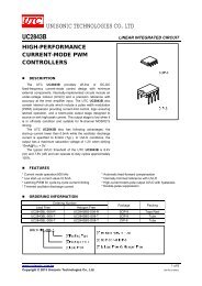
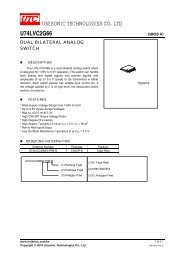
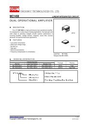
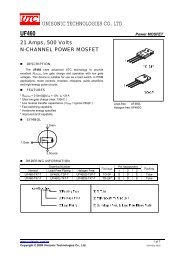
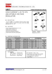
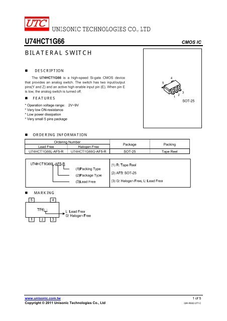
U74HCT1G66UNISONIC TECHNOLOGIES CO., LTDBILATERAL SWITCHCMOS IC• DESCRIPTIONThe U74HCT1G66 is a high-speed Si-gate CMOS devicethat provides an analog switch. The switch has two input/outputpins(Y and Z) and an active high enable input pin (E). When pin Eis low, the analog switch is turned off.• FEATURES* Operation voltage range: 2V~9V* Very low ON-resistance* Low power dissipation* Very small 5 pins package54123SOT-25• ORDERING INFORMATIONOrdering NumberPackagePackingLead FreeHalogen FreeU74HCT1G66L-AF5-R U74HCT1G66G-AF5-R SOT-25 Tape Reel• MARKINGwww.<strong>unisonic</strong>.<strong>co</strong>m.tw 1 of 5Copyright © 2011 Unisonic Technologies Co., LtdQW-R502-277.C
U74HCT1G66• PIN CONFIGURATIONCMOS ICV CC5E41 2 3Y Z GND• FUNCTION TABLEINPUT(EN)OUTPUT(Y/Z)HONLOFFNote: H: HIGH voltage level; L: LOW voltage level.• LOGIC DIAGRAMEYV DDV DDGNDZUNISONIC TECHNOLOGIES CO., LTD 2 of 5www.<strong>unisonic</strong>.<strong>co</strong>m.twQW-R502-277.C
U74HCT1G66CMOS IC• ABSOLUTE MAXIMUM RATINGS (unless otherwise specified)PARAMETER SYMBOL RATINGS UNITSupply Voltage V CC -0.5~11 VV CC or GND Current I CC ±50 mAInput Clamp Current I IK ±20 mASwitch Diode Current I SK ±20 mASwitch Current I S ±25 mAPower Dissipation200 mWP DDerate above T A >55°C 2.5 mW/KOperating Temperature T OPR -40 ~ + 125 ℃Storage Temperature T STG -65 ~ +150 ℃Note: Absolute maximum ratings are those values beyond which the device <strong>co</strong>uld be permanently damaged.Absolute maximum ratings are stress ratings only and functional device operation is not implied.• RECOMMENDED OPERATING CONDITIONSPARAMETER SYMBOL CONDITIONS MIN TYP MAX UNITSupply Voltage V CC 4.5 5.0 5.5 VInput Voltage V IN GND V CC VSwitch voltage V S GND V CC VInput Transition Rise or Fall Rate t R , t FV CC =2.0VV CC =10.0VV CC =4.5V 6 500V CC =6.0Vns• STATIC CHARACTERISTICS (T A =25°С)PARAMETER SYMBOL TEST CONDITIONS MIN TYP MAX UNITHigh-Level Input Voltage V IH V CC =4.5V~5.5V 2.0 VLow-Level Input Voltage V IL V CC =4.5V~5.5V 0.8 VInput Leakage Current I I(LEAK) V CC =5.5V, V IN =V CC or GND 0.1 1.0 μAQuiescent Supply CurrentI QV CC =4.5V~5.5V, V IN =V CC or GND,V IS =GND or V CC , V OS =V CC or GND1 10 μAAdditional supply current perinput∆ I Q V CC = 4.5 to 5.5V,V IN =V CC -2.1v 500 μAAnalog Switch OFF-stateV CC =5.5, V IN =V IH or V IL ;0.1 1I SCurrentON-state |V S |=V CC -GND0.1 1μAPEAK R V CC=4.5V, I S =1mA, V IS =V CC toON(PEAK)GND; V IN =V IH or V IL ;42 118V CC =4.5V, I S =1mA, V IS =GND;ON-Resistance29 95 ΩV IN =V IH or V IL ;RAIL R ON(RAIL)V CC =4.5V, I S =1mA, V IS =V CC ;35 106V IN =V IH or V IL ;• DYNAMIC CHARACTERISTICS (T A =25°С, C L =50pF, Input: t R =t F =6ns, unless otherwise specified )PARAMETER SYMBOL TEST CONDITIONS MINTYP(Note)MAX UNITPropagation Delay V IS to V OS t PHL /t PLH V CC =4.5V, R L =∞ 3 15 nsTurn-ON Time E to V OS t PZH /t PZL V CC =4.5V, R L =1KΩ 15 30 nsTurn-OFF Time E to V OS t PHZ /t PLZ V CC =4.5V, R L =1KΩ 13 44 nsNote : All typical values are measured at T A =25°СUNISONIC TECHNOLOGIES CO., LTD 3 of 5www.<strong>unisonic</strong>.<strong>co</strong>m.twQW-R502-277.C
U74HCT1G66CMOS IC• TEST CIRCUIT AND WAVEFORMSTest circuit for measuring ON-resistance (Ron)Test circuit for measuring OFF-state currentTest circuit for measuring ON-state currentUNISONIC TECHNOLOGIES CO., LTD 4 of 5www.<strong>unisonic</strong>.<strong>co</strong>m.twQW-R502-277.C
U74HCT1G66CMOS IC• TEST CIRCUIT AND WAVEFORMS(Cont.)Waveforms showing the Input (V IS ) to Output (V OS ) propagation delaysWaveforms showing the turn-on and turn-off times.E Input10%t F50%50%90%t PLZ10%Vos Outputt PHZVos Output90%Outputs enabledOutputs disabledNote: V IN =GND to V CCt Rt PZLt PZH50%50%OutputsenabledUTC assumes no responsibility for equipment failures that result from using products at values thatexceed, even momentarily, rated values (such as maximum ratings, operating <strong>co</strong>ndition ranges, orother parameters) listed in products specifications of any and all UTC products described or <strong>co</strong>ntainedherein. UTC products are not designed for use in life support appliances, devices or systems wheremalfunction of these products can be reasonably expected to result in personal injury. Reproduction inwhole or in part is prohibited without the prior written <strong>co</strong>nsent of the <strong>co</strong>pyright owner. The informationpresented in this document does not form part of any quotation or <strong>co</strong>ntract, is believed to be accurateand reliable and may be changed without notice.UNISONIC TECHNOLOGIES CO., LTD 5 of 5www.<strong>unisonic</strong>.<strong>co</strong>m.twQW-R502-277.C