Ultrasonic Sensors - TURCK USA
Ultrasonic Sensors - TURCK USA
Ultrasonic Sensors - TURCK USA

Create successful ePaper yourself
Turn your PDF publications into a flip-book with our unique Google optimized e-Paper software.
<strong>Ultrasonic</strong><br />
<strong>Sensors</strong><br />
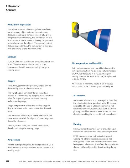
Principle of Operation<br />
The sensor emits an ultrasonic pulse that reflects<br />
back from any object entering the sonic cone.<br />
Because sound has a constant velocity at a given<br />
temperature and humidity, the time taken for this<br />
echo to return to the sensor is directly proportional<br />
to the distance of the object. The sensor’s output<br />
status is dependent on the comparison of this time<br />
with the setting of the detection zone.<br />
Medium<br />
<strong>TURCK</strong> ultrasonic transducers are calibrated for use<br />
in air. The sensors can also be used in other<br />
gaseous media with a corresponding change in<br />
sensing range.<br />
Targets<br />
Solid, fluid, granular and powdery targets can be<br />
detected by <strong>TURCK</strong> ultrasonic sensors.<br />
The variations of an “ideal” target should not<br />
exceed 0.15 mm (.006 in). Larger surface variations<br />
allow for larger alignment variations but may<br />
reduce sensing range.<br />
Target temperature affects the sensing range in<br />
that hot surfaces reflect sonic waves less than cold<br />
ones.<br />
The ultrasonic reflectivity of liquid surfaces is the<br />
same as that of solid, flat objects. Correct alignment<br />
should be observed.<br />
Textiles, foams, wool, etc. absorb sonic waves,<br />
thereby reducing the sensing range.<br />
Air pressure<br />
Normal atmospheric pressure changes of ±5% (at a<br />
fixed reference point) can cause a ±6% deviation in<br />
sensing range.<br />
Air temperature and humidity<br />
Both air temperature and humidity influence the<br />
sonic pulse duration. An air temperature increase<br />
of 20°C (68°F) results in a +3.5% change in<br />
sensing distance for M18, M30 or Q30 styles and<br />
+8% for CP40s.<br />
An increase in humidity results in an increased<br />
sound speed (max. 2%) compared with dry air.<br />
Air streams<br />
Air streams affect the echo propagation time, but<br />
the effects of air flow speeds of up to 10 m/s are<br />
negligible. The use of ultrasonic sensors is not<br />
recommended in turbulent areas such as above<br />
glowing metal because the sonic waves become<br />
distorted, making the echos difficult to evaluate.<br />
Dewing<br />
Normal concentrations of rain or snow falling in<br />
front of the sensor do not affect sensor operation.<br />
CP40 transducers are not protected against<br />
wetting. All other ultrasonic sensors are not<br />
damaged by water, but correct functionality may<br />
be impaired when wet. Therefore, the transducers<br />
should not be subjected to direct wetting during<br />
use.<br />
G5 <strong>TURCK</strong> Inc. 3000 Campus Drive Minneapolis, MN 55441 Application Support: 1-800-544-PROX Fax: (763) 553-0708 www.turck.com
Industrial<br />
Automation<br />
Sensor styles<br />
M18, M30 & Q30: these sensor styles have one<br />
transducer that functions both as emitter and<br />
receiver, which results in a larger blind zone. They<br />
have a narrow sonic cone (6°) and are especially<br />
suited for detection of small objects in a small area<br />
at a long distance.<br />
CP40 - these sensor styles have two transducers -<br />
one emitter and one receiver, which results in a<br />
smaller blind zone. They have a wide sonic cone<br />
(60°). The wide cone angle allows for a greater<br />
angle of inclination for the target. CP40 style<br />
sensors are especially suited for detecting objects in<br />
a large area.<br />
Simultaneous operation of several sensors<br />
When several ultrasonic sensors are used, mutual<br />
interference of the sonic cones may arise. To<br />
eliminate this problem, some of the sensors have<br />
synchronization and multiplexing features. For<br />
those sensors without these features, maintaining a<br />
minimum distance between sensors will also solve<br />
this problem.<br />
Synchronization<br />
Synchronization of ultrasonic sensors causes the<br />
sensors to emit their sonic pulses simultaneously.<br />
Using RUC...M30, RU..-Q30 or RU..-M18 sensors,<br />
up to six sensors may be synchronized by tying<br />
their X1 lines.<br />
Multiplexing<br />
Multiplexing the sensors causes them to emit their<br />
pulses at pre-defined intervals, independent of one<br />
another. This eliminates the possibility of mutual<br />
interference and of sensors seeing targets that are<br />
actually in front of other sensors. The more sensors<br />
that are operated alternately, the lower the<br />
switching frequency.<br />
The X1 line of sensors RUC..-M30, RU..-Q30 and<br />
RU..-M18 can be used as an enable input for<br />
multiplexing purposes. An X1 input of +24 V<br />
enables the sensor while an X1 input of 0 V<br />
disables it. Multiplexing via the X1 line instead of<br />
by powering down the sensors has the advantage<br />
that only the response time has to be considered<br />
and not the time delay before availability.<br />
<strong>TURCK</strong> Inc. 3000 Campus Drive Minneapolis, MN 55441 Application Support: 1-800-544-PROX Fax: (763) 553-0708 www.turck.com G6<br />
<strong>Ultrasonic</strong>
<strong>Ultrasonic</strong><br />
<strong>Sensors</strong><br />
Range adjustments<br />
M30 and CP40 style sensors have two<br />
potentiometers to enable both foreground and<br />
background suppression. Q30 and discrete M18<br />
style sensors have one potentiometer to enable<br />
background suppression only.<br />
Analog M18 sensors have a fixed range.<br />
Sensing ranges given are at nominal conditions,<br />
i.e. Tu = +20°C (68°F) using a standard target,<br />
vertically aligned, with reflective surface<br />
(metal, 1 mm thick).<br />
<strong>Sensors</strong> with two switch points<br />
RUC...2AP8X - the potentiometers on these<br />
sensors set the far limits of each detection zone.<br />
Potentiometer S1 sets the far limit of Zone 1,<br />
which begins at the end of the blind zone.<br />
Potentiometer S2 sets the far limit of Zone 2,<br />
which begins at the far limit of Zone 1 (Figure 1).<br />
Figure 1<br />
<strong>Sensors</strong> with one switch point<br />
CP40 - potentiometer S1 sets the near limit while<br />
potentiometer S2 sets the depth of the detection<br />
zone. This allows both foreground and background<br />
suppression. Changes to S1 will cause the far limit<br />
to follow (Figure 2).<br />
Figure 2<br />
Q30 and discrete M18 - one potentiometer sets<br />
the far limit of the detection zone. The near limit is<br />
not adjustable, and is determined by the blind<br />
zone. This allows for background suppression only<br />
(Figure 3).<br />
Figure 3<br />
M30 - potentiometers S1 and S2 set the near and<br />
far limits of the detection zone. This allows for<br />
foreground and background suppression. The pots<br />
are independent of each other (Figure 4).<br />
Figure 4<br />
G7 <strong>TURCK</strong> Inc. 3000 Campus Drive Minneapolis, MN 55441 Application Support: 1-800-544-PROX Fax: (763) 553-0708 www.turck.com
Industrial<br />
Automation<br />
Sensor Type e (cm) f (cm) g (cm) h (cm)<br />
RU20-M18K- 80 6 3 1.5<br />
RU70-M18K- 280 18 10 5.0<br />
RUN20-M18K 80 6 3 1.5<br />
RUN70-M18K- 280 18 10 5.0<br />
RUR20-M18K- 80 6 3 1.5<br />
RUR70-M18K- 280 18 10 5.0<br />
RU20-M18KS- 80 6 3 1.5<br />
RU70-M18KS- 280 18 10 5.0<br />
RUN20-M18KS- 80 6 3 1.5<br />
RUN70-M18KS- 280 18 10 5.0<br />
RUR20-M18KS- 80 6 3 1.5<br />
RUR70-M18KS- 280 18 10 5.0<br />
RU 30-M18- ≥120 ≥15 ≥6 ≥3<br />
RU100-M18- ≥400 ≥60 ≥30 ≥15<br />
RU 30-M30- ≥120 ≥15 ≥6 ≥3<br />
RU100-M30- ≥400 ≥60 ≥30 ≥15<br />
RU600-M3065- ≥2500 ≥250 ≥80 ≥40<br />
RUC 30-M30- ≥120 ≥15 ≥6 ≥3<br />
RUC130-M30- ≥400 ≥60 ≥30 ≥15<br />
RUC300-M3047- ≥1200 ≥150 ≥60 ≥30<br />
RUC600-M3065- ≥2500 ≥250 ≥80 ≥40<br />
RU 30-Q30 ≥120 ≥15 ≥6 ≥3<br />
RU100-Q30 ≥400 ≥60 ≥30 ≥15<br />
RU100-CP40-AP6X2 ≥600 ≥100 ≥120 ≥60<br />
RU100-CP40-LIUX ≥600 ≥100 ≥120 ≥60<br />
1) The greater the angle α, the larger the distance f. The minimum f values in the table refer to α = 0°.<br />
Mounting Considerations<br />
<strong>TURCK</strong> Inc. 3000 Campus Drive Minneapolis, MN 55441 Application Support: 1-800-544-PROX Fax: (763) 553-0708 www.turck.com G8<br />
<strong>Ultrasonic</strong>