Series CQM - Coast Pneumatics
Series CQM - Coast Pneumatics
Series CQM - Coast Pneumatics

Create successful ePaper yourself
Turn your PDF publications into a flip-book with our unique Google optimized e-Paper software.
<strong>Series</strong> Variations<br />
<strong>CQM</strong><br />
12, 16<br />
20, 25<br />
32, 40<br />
50<br />
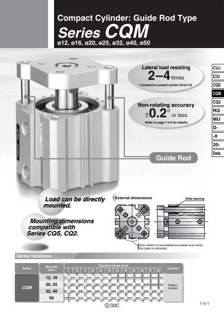
Compact Cylinder: Guide Rod Type<br />
<strong>Series</strong> <strong>CQM</strong><br />
ø12, ø16, ø20, ø25, ø32, ø40, ø50<br />
Load can can be be directly<br />
mounted.<br />
Mounting dimensions<br />
compatible with with<br />
<strong>Series</strong> CQS, CQ2.<br />
<strong>Series</strong><br />
Bore size<br />
(mm)<br />
Guide Rod<br />
External dimensions Slide bearing<br />
Standard stroke (mm)<br />
5 10 15 20 25 30 35 40 45 50 75 100<br />
Lateral load resisting<br />
2–4times<br />
∗ Compared to compact cylinder <strong>Series</strong> CQ<br />
Non-rotating accuracy<br />
±0.2° or less<br />
Refer to page 7-5-4 for details.<br />
Auto switch is mountable/removable even when<br />
the plate is retracted.<br />
Cushion<br />
Rubber<br />
bumper<br />
7-5-1<br />
CUJ<br />
CU<br />
CQS<br />
<strong>CQM</strong><br />
CQ2<br />
RQ<br />
MU<br />
D-<br />
-X<br />
20-<br />
Data<br />
1
B<br />
A<br />
7-5-2<br />
Compact Cylinder: Guide Rod Type<br />
Double Acting, Single Rod<br />
<strong>Series</strong> <strong>CQM</strong><br />
ø12, ø16, ø20, ø25, ø32, ø40, ø50<br />
With auto switch<br />
Mounting<br />
Through-hole (standard)<br />
Both end tapped style (ø32 to ø50)<br />
Note 1) Cylinder bodies of ø12 to ø25 are<br />
common for both B (Through-<br />
hole) and A (Both end tapped)<br />
types. Symbol to order is unified<br />
to “B” for those sizes.<br />
Note 2) Please contact SMC for the other<br />
mounting types.<br />
Symbol<br />
Nil<br />
TN<br />
TF<br />
NN<br />
M thread<br />
Rc<br />
NPT<br />
G<br />
M thread<br />
NPT<br />
<strong>CQM</strong><br />
CDQM<br />
12<br />
16<br />
20<br />
25<br />
32<br />
40<br />
50<br />
B<br />
B<br />
Bore size<br />
12 mm<br />
16 mm<br />
20 mm<br />
25 mm<br />
32 mm<br />
40 mm<br />
50 mm<br />
20<br />
20<br />
Thread type<br />
Port thread Mounting thread Bore size<br />
M thread<br />
Inch thread<br />
ø12 to ø25<br />
ø32 to ø50<br />
ø12 to ø25<br />
ø32 to ø50<br />
How to Order<br />
10<br />
10<br />
M9B<br />
Note 3) M thread to be used for without auto switch type of ø32, 5 stroke exceptionally.<br />
S<br />
Number of auto switches<br />
Nil<br />
S<br />
n<br />
2 pcs.<br />
1 pc.<br />
“n” pcs.<br />
Auto switch type<br />
Nil Without auto switch (Built-in magnet)<br />
∗ For the applicable auto switch model, refer to the table below.<br />
∗ Auto switches are shipped together, (but not assembled).<br />
(Except D-P5DWL type)<br />
Cylinder stroke (mm)<br />
For “Standard Stroke” and “Manufacuture of intermediate of<br />
Stroke”, refer to page 7-5-3.<br />
Applicable Auto Switch/Refer to page 7-9-1 for further inforrmation on auto switches.<br />
Type<br />
Special<br />
function<br />
Electrical<br />
entry<br />
Wiring<br />
(output)<br />
Load voltage<br />
DC AC<br />
Rail mounting<br />
Perpendicular In-line<br />
Direct mounting<br />
Perpendicular In-line<br />
Lead wire length (m)∗<br />
0.5 3 5<br />
(Nil) (L) (Z)<br />
Applicable<br />
load<br />
3-wire<br />
(NPN equiv.)<br />
5 V<br />
A76H A96V A96<br />
IC<br />
circuit<br />
Grommet<br />
12 V<br />
200 V A72<br />
A73<br />
A72H<br />
A73H<br />
Connector<br />
2-wire<br />
24 V<br />
5 V, 12 V<br />
12 V<br />
12 V<br />
5 V, 12 V<br />
100 V A80<br />
A73C<br />
A80C<br />
A80H A90V<br />
A93V<br />
A90<br />
A93<br />
IC circuit<br />
Relay,<br />
PLC<br />
IC circuit<br />
Diagnostic indication<br />
(2-color indication) Grommet Yes<br />
A79W<br />
Grommet<br />
3-wire (NPN)<br />
3-wire (PNP)<br />
5 V, 12 V<br />
F7NV<br />
F7PV<br />
F79<br />
F7P<br />
M9NV<br />
M9PV<br />
M9N<br />
M9P<br />
IC circuit<br />
Connector<br />
2-wire<br />
12 V<br />
F7BV<br />
J79C<br />
J79 M9BV M9B<br />
Diagnostic indication<br />
(2-color indication)<br />
Grommet<br />
Water resistant<br />
(2-color indication)<br />
3-wire (NPN)<br />
3-wire (PNP)<br />
2-wire<br />
24 V 5 V, 12 V<br />
12 V<br />
F7NWV<br />
F7BWV<br />
F7BAV<br />
F79W<br />
F7PW<br />
J79W<br />
F7BA<br />
F9NWV<br />
F9PWV<br />
F9BWV<br />
F9NW<br />
F9PW<br />
F9BW<br />
F9BA<br />
IC circuit<br />
Magnetic field resistant<br />
(2-color indication)<br />
5 V, 12 V<br />
P5DW<br />
Relay,<br />
ø32 to ø50 ø12 to ø50<br />
None<br />
(N)<br />
PLC<br />
Solid state switch Reed switch<br />
Without<br />
auto switch<br />
With auto switch<br />
Yes<br />
No<br />
No Yes<br />
Yes<br />
∗ Lead wire length symbols: 0.5 m�������� Nil (Example) A73C<br />
∗ Solid state switches marked with a “�” symbol are produced upon receipt of order.<br />
3 m�������� L A73CL<br />
5 m�������� Z A73CZ<br />
None.�������� N A73CN<br />
• In addition to the models in the above table, there are some other auto switches that are applicable. For more information, please refer to page 7-5-11.<br />
• D-P5DWL type: ø40 and ø50 only available.<br />
Made to Order Specifications<br />
• -50 Without indicator light<br />
• -61 Flexible lead wire<br />
• Pre-wire connector<br />
Indicator light<br />
Please contact SMC.<br />
2
Bore size<br />
(mm)<br />
12<br />
16<br />
20<br />
25<br />
32<br />
40<br />
50<br />
Caution<br />
This product should not be used as a stopper.<br />
Theoretical Output<br />
Operating<br />
direction<br />
IN<br />
OUT<br />
IN<br />
OUT<br />
IN<br />
OUT<br />
IN<br />
OUT<br />
IN<br />
OUT<br />
IN<br />
OUT<br />
IN<br />
OUT<br />
Unit: N<br />
Operating pressure (MPa)<br />
0.3 0.5 0.7<br />
25 42 59<br />
34 57 79<br />
45 75 106<br />
60 101 141<br />
71 118 165<br />
94 157 220<br />
113 189 264<br />
147 245 344<br />
181 302 422<br />
241 402 563<br />
317 528 739<br />
377 628 880<br />
495 825 1150<br />
589 982 1370<br />
Auto Switch Mounting Bracket Weight<br />
Mounting<br />
bracket part no.<br />
BQ-2<br />
BQP1-050<br />
Applicable cylinder<br />
bore size<br />
ø32 to ø50<br />
ø40, ø50<br />
Weight<br />
(g)<br />
1.5<br />
16<br />
Compact Cylinder: Guide Rod Type<br />
Double Acting, Single Rod<br />
Specifications<br />
Type<br />
Action<br />
Fluid<br />
Proof pressure<br />
Maximum operating pressure<br />
Minimum operating ø12, 16<br />
pressure<br />
ø20 to 50<br />
Ambient and fluid temperature<br />
Cushion<br />
Stroke length tolerance<br />
Mounting<br />
Piston speed<br />
Standard Stroke<br />
ø12 to 40<br />
ø50<br />
Manufacture of Intermediate Stroke<br />
Description<br />
Description<br />
<strong>Series</strong> <strong>CQM</strong><br />
Pneumatic (non-lube)<br />
Double acting, Single rod<br />
Air<br />
1.5 MPa<br />
1.0 MPa<br />
0.12 MPa<br />
0.1 MPa<br />
Without auto switch: –10°C to70°C (with no freezing)<br />
With auto switch: –10°C to 60°C (with no freezing)<br />
Rubber bumper on both ends<br />
+1.0 mm<br />
0<br />
Through-hole<br />
50 to 500 mm/s<br />
50 to 300 mm/s<br />
Bore size (mm) Standard stroke (mm)<br />
12, 16 5, 10, 15, 20, 25, 30<br />
20, 25 5, 10, 15, 20, 25, 30, 35, 40, 45, 50<br />
32, 40 5, 10, 15, 20, 25, 30, 35, 40, 45, 50, 75, 100<br />
50<br />
10, 15, 20, 25, 30, 35, 40, 45, 50, 75, 100<br />
Bore size (mm)<br />
Intermediate stroke range<br />
Bore size (mm) Intermediate stroke range (mm)<br />
12, 16<br />
1 to 29<br />
20, 25<br />
1 to 49<br />
12 to 32 Available in 1 mm stroke increments 32<br />
1 to 99<br />
40, 50 Available in 5 mm stroke increments 40, 50<br />
5 to 95<br />
Example) Part no.: <strong>CQM</strong>B32–57 It is produced by installing a 18 mm spacer in a standard stroke<br />
cylinder <strong>CQM</strong>B32-75. B dimension: 108 mm.<br />
Weight<br />
Without Auto Switch<br />
Bore size<br />
(mm)<br />
12<br />
16<br />
20<br />
25<br />
32<br />
40<br />
50<br />
5<br />
44<br />
56<br />
92<br />
125<br />
182<br />
269<br />
–<br />
Bore size<br />
(mm) 5<br />
12 52<br />
16 66<br />
20 122<br />
25 168<br />
32 241<br />
40 345<br />
50 –<br />
Spacers are installed in a<br />
standard stroke cylinder.<br />
10<br />
52<br />
67<br />
107<br />
143<br />
205<br />
295<br />
500<br />
10<br />
59<br />
77<br />
138<br />
186<br />
264<br />
371<br />
618<br />
15<br />
60<br />
77<br />
122<br />
162<br />
228<br />
320<br />
540<br />
15<br />
68<br />
87<br />
153<br />
205<br />
287<br />
396<br />
658<br />
20<br />
69<br />
87<br />
137<br />
180<br />
250<br />
345<br />
580<br />
20<br />
77<br />
97<br />
168<br />
223<br />
309<br />
421<br />
698<br />
25<br />
77<br />
97<br />
152<br />
198<br />
274<br />
370<br />
620<br />
25<br />
84<br />
107<br />
182<br />
240<br />
333<br />
447<br />
738<br />
Cylinder stroke (mm)<br />
30<br />
86<br />
108<br />
167<br />
216<br />
297<br />
396<br />
661<br />
With Auto Switch (Built-in magnet)<br />
30<br />
93<br />
118<br />
197<br />
258<br />
356<br />
473<br />
779<br />
35<br />
–<br />
–<br />
183<br />
234<br />
320<br />
421<br />
701<br />
Cylinder stroke (mm)<br />
Add each weight of auto switches and mounting brackets.<br />
For the auto switch weight, refer to page 7-9-1.<br />
35<br />
–<br />
–<br />
213<br />
277<br />
379<br />
498<br />
819<br />
40<br />
–<br />
–<br />
198<br />
252<br />
343<br />
446<br />
740<br />
40<br />
–<br />
–<br />
227<br />
295<br />
401<br />
523<br />
858<br />
45<br />
–<br />
–<br />
213<br />
270<br />
366<br />
471<br />
780<br />
45<br />
–<br />
–<br />
242<br />
313<br />
425<br />
548<br />
898<br />
50<br />
–<br />
–<br />
227<br />
288<br />
389<br />
497<br />
821<br />
50<br />
–<br />
–<br />
257<br />
331<br />
448<br />
574<br />
939<br />
75<br />
–<br />
–<br />
–<br />
–<br />
0553<br />
0692<br />
1133<br />
75<br />
–<br />
–<br />
–<br />
–<br />
0564<br />
0705<br />
1147<br />
Unit: g<br />
100<br />
–<br />
–<br />
–<br />
–<br />
0669<br />
0823<br />
1341<br />
Unit: g<br />
100<br />
–<br />
–<br />
–<br />
–<br />
0680<br />
0836<br />
1355<br />
7-5-3<br />
CUJ<br />
CU<br />
CQS<br />
<strong>CQM</strong><br />
CQ2<br />
RQ<br />
MU<br />
D-<br />
-X<br />
20-<br />
Data<br />
3
<strong>Series</strong> <strong>CQM</strong><br />
Plate Non-rotating Accuracy<br />
Non-rotating accuracy without load is designed to be same or less than the figures shown in the table below at the retracted cylinder end (plate).<br />
Plate Allowable Rotational Torque<br />
Plate allowable lateral load (N)<br />
Bore size<br />
(mm)<br />
12<br />
16<br />
20<br />
25<br />
32<br />
40<br />
50<br />
100<br />
10<br />
7-5-4<br />
Bore size (mm)<br />
12, 16<br />
20 to 50<br />
5<br />
0.11<br />
0.15<br />
0.37<br />
0.40<br />
0.66<br />
1.06<br />
–<br />
10<br />
0.10<br />
0.12<br />
0.32<br />
0.35<br />
0.59<br />
0.96<br />
1.70<br />
ø12, ø16<br />
15<br />
0.08<br />
0.11<br />
0.28<br />
0.31<br />
0.53<br />
0.88<br />
1.56<br />
Non-rotating accuracy<br />
±0.2°<br />
±0.1°<br />
Make sure to operate strictly within the allowable rotation<br />
torque range to the plate.<br />
Operation outside of this range may result in shorter service life or damage<br />
to the devise.<br />
Plate Allowable Lateral Load<br />
ø20, ø25<br />
20<br />
0.07<br />
0.10<br />
0.25<br />
0.28<br />
0.49<br />
0.81<br />
1.45<br />
1<br />
0 10 20 30 40 50 60 70 80 90 100<br />
Stroke + Eccentric distance (mm)<br />
25<br />
0.07<br />
0.09<br />
0.23<br />
0.25<br />
0.45<br />
0.75<br />
1.35<br />
Cylinder stroke (mm)<br />
30<br />
0.06<br />
0.08<br />
0.21<br />
0.23<br />
0.42<br />
0.70<br />
1.26<br />
Make sure to operate strictly within the allowable lateral load<br />
range to the plate.<br />
Operation outside of this range may result in shorter service life or damage<br />
to the devise.<br />
Lateral load<br />
Stroke<br />
Eccentric distance<br />
ø50<br />
ø40<br />
ø32<br />
35<br />
–<br />
–<br />
0.19<br />
0.21<br />
0.39<br />
0.65<br />
1.19<br />
40<br />
–<br />
–<br />
0.18<br />
0.20<br />
0.36<br />
0.61<br />
1.12<br />
45<br />
–<br />
–<br />
0.17<br />
0.18<br />
0.34<br />
0.58<br />
1.06<br />
50<br />
–<br />
–<br />
0.16<br />
0.17<br />
0.32<br />
0.55<br />
1.01<br />
75<br />
–<br />
–<br />
–<br />
–<br />
0.25<br />
0.43<br />
0.80<br />
Allowable Kinetic Energy<br />
Unit: N.m<br />
Make sure to operate strictly within the allowable range of<br />
the load weight and maximum speed.<br />
Operation outside of this range may cause excessive impact, which may<br />
result in the damage to the devise.<br />
Load weight (kg)<br />
100.0<br />
10.0<br />
1.0<br />
T<br />
100<br />
–<br />
–<br />
–<br />
–<br />
0.20<br />
0.36<br />
0.67<br />
0.1<br />
10 100 1000<br />
T<br />
Maximum speed (mm/s)<br />
+θ<br />
–θ<br />
Operating pressure: 0.5 MPa<br />
ø50<br />
ø40<br />
ø32<br />
ø25<br />
ø20<br />
ø16<br />
ø12<br />
4
Construction<br />
ø12 to 25<br />
o t !5!1 w !7 !2 q r !6 e !3<br />
ø32 to 50<br />
Compact Cylinder: Guide Rod Type<br />
Double Acting, Single Rod<br />
- -<br />
!0 u y<br />
o t !5 !1 wi<br />
!7 !2 q r !6 e !3<br />
!0 u y<br />
Component Parts<br />
With auto switch<br />
(Built-in magnet)<br />
With auto switch<br />
(Built-in magnet)<br />
No. Description<br />
Material<br />
q Cylinder tube<br />
Aluminum alloy<br />
w Collar<br />
Aluminum alloy<br />
Aluminum alloy casted<br />
e Piston<br />
Aluminum alloy<br />
r Piston rod<br />
Stainless steel<br />
Carbon steel<br />
t Plate<br />
Aluminum alloy<br />
y Guide rod<br />
Stainless steel<br />
u Bushing<br />
Oil-impregnated sintered alloy<br />
i Bushing<br />
Bronze casting<br />
o Hexagon socket head cap screw<br />
Carbon steel<br />
!0 Hexagon socket head cap screw<br />
Carbon steel<br />
!1 Snap ring<br />
Carbon tool steel<br />
!2 Bumper A<br />
Urethan<br />
!3 Bumper B<br />
Urethan<br />
!4 Magnet<br />
—<br />
!5 Rod seal<br />
NBR<br />
!6 Piston seal<br />
NBR<br />
!7 Gasket<br />
NBR<br />
<strong>Series</strong> <strong>CQM</strong><br />
!4<br />
!4<br />
Note<br />
Hard anodized<br />
ø12 to ø40 Anodized<br />
ø50 Chromated, Coated<br />
Chromated<br />
ø12 to ø25<br />
ø32 to ø50 Hard chrome plated<br />
Anodized<br />
Hard chrome plated<br />
ø50 only<br />
Nickel plated<br />
Nickel plated<br />
Phosphate coated<br />
7-5-5<br />
CUJ<br />
CU<br />
CQS<br />
<strong>CQM</strong><br />
CQ2<br />
RQ<br />
MU<br />
D-<br />
-X<br />
20-<br />
Data<br />
5
<strong>Series</strong> <strong>CQM</strong><br />
Mounting Bolt<br />
Mounting method: Mounting bolt for through-hole<br />
style of <strong>CQM</strong>B is available as an<br />
option.<br />
Ordering: Add the word “Bolt” in front of<br />
the bolts to be used.<br />
Example) Bolt M3 x 25 2 pcs.<br />
Mounting Bolt for <strong>CQM</strong>/Without Auto Switch<br />
7-5-6<br />
Model C D Mounting bolt<br />
<strong>CQM</strong>B12-5<br />
-10<br />
-15<br />
-20<br />
-25<br />
-30<br />
<strong>CQM</strong>B16-5<br />
-10<br />
-15<br />
-20<br />
-25<br />
-30<br />
<strong>CQM</strong>B20-5<br />
-10<br />
-15<br />
-20<br />
-25<br />
-30<br />
-35<br />
-40<br />
-45<br />
-50<br />
Note) To install a through-hole type mounting bolt, bore size 12 to 25 mm,<br />
make sure to use the flat washer that is provided.<br />
Mounting Bolt for CDQM/With Auto Switch (Built-in magnet)<br />
Mounting<br />
bolt<br />
OA thread<br />
Model C D Mounting bolt Model C D Mounting bolt<br />
Model C D Mounting bolt Model C D Mounting bolt Model C D Mounting bolt<br />
CDQMB12-5<br />
-10<br />
-15<br />
-20<br />
-25<br />
-30<br />
CDQMB16-5<br />
-10<br />
-15<br />
-20<br />
-25<br />
-30<br />
CDQMB20-5<br />
-10<br />
-15<br />
-20<br />
-25<br />
-30<br />
-35<br />
-40<br />
-45<br />
-50<br />
6.5<br />
6.5<br />
6.5<br />
6.5<br />
6.5<br />
6.5<br />
25<br />
30<br />
35<br />
40<br />
45<br />
50<br />
25<br />
30<br />
35<br />
40<br />
45<br />
50<br />
25<br />
30<br />
35<br />
40<br />
45<br />
50<br />
55<br />
60<br />
65<br />
70<br />
30<br />
35<br />
40<br />
45<br />
50<br />
55<br />
30<br />
35<br />
40<br />
45<br />
50<br />
55<br />
35<br />
40<br />
45<br />
50<br />
55<br />
60<br />
65<br />
70<br />
75<br />
80<br />
M3 x 25<br />
x 30<br />
x 35<br />
x 40<br />
x 45<br />
x 50<br />
M3 x 25<br />
x 30<br />
x 35<br />
x 40<br />
x 45<br />
x 50<br />
M5 x 25<br />
x 30<br />
x 35<br />
x 40<br />
x 45<br />
x 50<br />
x 55<br />
x 60<br />
x 65<br />
x 70<br />
M3 x 30<br />
x 35<br />
x 40<br />
x 45<br />
x 50<br />
x 55<br />
M3 x 30<br />
x 35<br />
x 40<br />
x 45<br />
x 50<br />
x 55<br />
M5 x 35<br />
x 40<br />
x 45<br />
x 50<br />
x 55<br />
x 60<br />
x 65<br />
x 70<br />
x 75<br />
x 80<br />
<strong>CQM</strong>B25-5<br />
-10<br />
-15<br />
-20<br />
-25<br />
-30<br />
-35<br />
-40<br />
-45<br />
-50<br />
<strong>CQM</strong>B32-5<br />
-10<br />
-15<br />
-20<br />
-25<br />
-30<br />
-35<br />
-40<br />
-45<br />
-50<br />
-75<br />
-100<br />
CDQMB25-5<br />
-10<br />
-15<br />
-20<br />
-25<br />
-30<br />
-35<br />
-40<br />
-45<br />
-50<br />
CDQMB32-5<br />
-10<br />
-15<br />
-20<br />
-25<br />
-30<br />
-35<br />
-40<br />
-45<br />
-50<br />
-75<br />
-100<br />
8.5<br />
9<br />
8.5<br />
9<br />
30<br />
35<br />
40<br />
45<br />
50<br />
55<br />
60<br />
65<br />
70<br />
75<br />
30<br />
35<br />
40<br />
45<br />
50<br />
55<br />
60<br />
65<br />
70<br />
75<br />
110<br />
135<br />
40<br />
45<br />
50<br />
55<br />
60<br />
65<br />
70<br />
75<br />
80<br />
85<br />
40<br />
45<br />
50<br />
55<br />
60<br />
65<br />
70<br />
75<br />
80<br />
85<br />
110<br />
135<br />
M5 x 30<br />
x 35<br />
x 40<br />
x 45<br />
x 50<br />
x 55<br />
x 60<br />
x 65<br />
x 70<br />
x 75<br />
M5 x 30<br />
x 35<br />
x 40<br />
x 45<br />
x 50<br />
x 55<br />
x 60<br />
x 65<br />
x 70<br />
x 75<br />
x 110<br />
x 135<br />
M5 x 40<br />
x 45<br />
x 50<br />
x 55<br />
x 60<br />
x 65<br />
x 70<br />
x 75<br />
x 80<br />
x 85<br />
M5 x 40<br />
x 45<br />
x 50<br />
x 55<br />
x 60<br />
x 65<br />
x 70<br />
x 75<br />
x 80<br />
x 85<br />
x 110<br />
x 135<br />
<strong>CQM</strong>B40-5<br />
-10<br />
-15<br />
-20<br />
-25<br />
-30<br />
-35<br />
-40<br />
-45<br />
-50<br />
-75<br />
-100<br />
<strong>CQM</strong>B50-10<br />
-15<br />
-20<br />
-25<br />
-30<br />
-35<br />
-40<br />
-45<br />
-50<br />
-75<br />
-100<br />
CDQMB40-5<br />
-10<br />
-15<br />
-20<br />
-25<br />
-30<br />
-35<br />
-40<br />
-45<br />
-50<br />
-75<br />
-100<br />
CDQMB50-10<br />
-15<br />
-20<br />
-25<br />
-30<br />
-35<br />
-40<br />
-45<br />
-50<br />
-75<br />
-100<br />
7.5<br />
12.5<br />
7.5<br />
12.5<br />
35<br />
40<br />
45<br />
50<br />
55<br />
60<br />
65<br />
70<br />
75<br />
80<br />
115<br />
140<br />
45<br />
50<br />
55<br />
60<br />
65<br />
70<br />
75<br />
80<br />
85<br />
120<br />
145<br />
45<br />
50<br />
55<br />
60<br />
65<br />
70<br />
75<br />
80<br />
85<br />
90<br />
115<br />
140<br />
55<br />
60<br />
65<br />
70<br />
75<br />
80<br />
85<br />
90<br />
95<br />
120<br />
145<br />
M5 x 35<br />
x 40<br />
x 45<br />
x 50<br />
x 55<br />
x 60<br />
x 65<br />
x 70<br />
x 75<br />
x 80<br />
x 115<br />
x 140<br />
M6 x 45<br />
x 50<br />
x 55<br />
x 60<br />
x 65<br />
x 70<br />
x 75<br />
x 80<br />
x 85<br />
x 120<br />
x 145<br />
M5 x 45<br />
x 50<br />
x 55<br />
x 60<br />
x 65<br />
x 70<br />
x 75<br />
x 80<br />
x 85<br />
x 90<br />
x 115<br />
x 140<br />
M6 x 55<br />
x 60<br />
x 65<br />
x 70<br />
x 75<br />
x 80<br />
x 85<br />
x 90<br />
x 95<br />
x 120<br />
x 145<br />
6
Dimensions<br />
ø12 to ø25<br />
Bore size<br />
(mm)<br />
12<br />
16<br />
20<br />
25<br />
Bore size<br />
(mm)<br />
12<br />
16<br />
20<br />
25<br />
øIA<br />
KA<br />
V<br />
KA<br />
Stroke range<br />
(mm)<br />
5 to 30<br />
5 to 30<br />
5 to 50<br />
5 to 50<br />
KA<br />
10<br />
14<br />
17<br />
22<br />
V<br />
KB<br />
7.1<br />
9.9<br />
12<br />
15.6<br />
ø12<br />
(�KB)<br />
M<br />
EB<br />
EA<br />
ø20, ø25<br />
Without auto switch<br />
A<br />
26.5<br />
26.5<br />
32<br />
35.5<br />
L<br />
3.5<br />
3.5<br />
4.5<br />
5<br />
B<br />
17<br />
17<br />
19.5<br />
22.5<br />
M<br />
15.5<br />
20<br />
25.5<br />
28<br />
N<br />
3.5<br />
3.5<br />
5.4<br />
5.4<br />
Compact Cylinder: Guide Rod Type<br />
Double Acting, Single Rod<br />
With auto switch<br />
A B<br />
EA EB F<br />
—<br />
HA<br />
NN —<br />
OA<br />
NN<br />
31.5 22 25 24 5 M3 x 0.5 4-40UNC M4 x 0.7 8-32UNC<br />
31.5 22 29 28 5 M3 x 0.5 4-40UNC M4 x 0.7 8-32UNC<br />
42 29.5 36 34 5.5 M4 x 0.7 6-32UNC M6 x 1.0 1/4-20UNC<br />
45.5 32.5 40 38 5.5 M5 x 0.8 10-32UNF M6 x 1.0 1/4-20UNC<br />
OB<br />
6.5<br />
6.5<br />
9<br />
9<br />
ø16<br />
2 x 2-øOB counterbore with depth RB<br />
V<br />
2-øHB through<br />
2-øHA through<br />
M<br />
EB<br />
EA<br />
Flat washer<br />
Q<br />
7.5<br />
7.5<br />
9<br />
11<br />
Note) For the following bore/stroke sizes, the through-hole is threaded.<br />
Standard without auto switch: ø12 and ø16; 5 stroke, ø25; 5 to 10 stroke<br />
Built-in magnet with auto switch: ø20; 5 stroke<br />
øIB<br />
T<br />
RA<br />
7<br />
7<br />
10<br />
10<br />
RB<br />
4<br />
4<br />
7<br />
7<br />
T<br />
0.5<br />
0.5<br />
1<br />
1<br />
L<br />
V<br />
Q<br />
14.9<br />
20<br />
26<br />
30<br />
Note)<br />
2 x 2-RA<br />
W B + Stroke<br />
A + Stroke<br />
W<br />
6<br />
6<br />
8<br />
8<br />
2-M5 x 0.8<br />
<strong>Series</strong> <strong>CQM</strong><br />
Auto switch<br />
F<br />
HB<br />
3<br />
3<br />
4<br />
5<br />
2-øN through<br />
2 x 2-OA<br />
(RB)<br />
IA<br />
32<br />
38<br />
47<br />
52<br />
(mm)<br />
IB<br />
31.5<br />
37<br />
45.5<br />
50.5<br />
7-5-7<br />
CUJ<br />
CU<br />
CQS<br />
<strong>CQM</strong><br />
CQ2<br />
RQ<br />
MU<br />
D-<br />
-X<br />
20-<br />
Data<br />
7
<strong>Series</strong> <strong>CQM</strong><br />
Dimensions<br />
ø32 to ø50<br />
Auto switch<br />
D-A7/A8<br />
7-5-8<br />
22<br />
11<br />
Min. lead wire<br />
bending radius 10<br />
Bore size<br />
(mm)<br />
32<br />
40<br />
50<br />
Bore size<br />
(mm)<br />
32<br />
40<br />
50<br />
V<br />
KA<br />
øIA<br />
KA<br />
U<br />
øIB<br />
(�KB)<br />
M<br />
EC<br />
EB<br />
EA<br />
S<br />
HA<br />
—, TN, TF NN<br />
OA<br />
—, TN, TF NN<br />
HB<br />
M5 x 0.8 10-32UNF M6 x 1.0 1/4-20UNC 5<br />
M5 x 0.8 10-32UNF M6 x 1.0 1/4-20UNC 5<br />
M6 x 1.0 1/4-20UNC M8 x 1.25 5/16-18UNC 6<br />
IA<br />
2-øHA through<br />
2-øHB through<br />
J<br />
60<br />
69<br />
86<br />
2-øN through<br />
2 x 2-øOB counterbore with depth RB<br />
Z<br />
IB<br />
58.5<br />
67.5<br />
84.5<br />
M<br />
EC<br />
EB<br />
EA<br />
Stroke<br />
Without auto switch<br />
range<br />
(mm) A B F Q<br />
—<br />
P<br />
TN TF NN<br />
5<br />
10 to 50<br />
75, 100<br />
40<br />
50<br />
23<br />
33<br />
5.5<br />
7.5<br />
11.5<br />
10.5<br />
M5 x 0.8<br />
Rc1/8<br />
—<br />
NPT1/8<br />
—<br />
G1/8<br />
M5 x 0.8<br />
NPT1/8<br />
5 to 50<br />
75, 100<br />
46.5<br />
56.5<br />
29.5<br />
39.5<br />
8 11 Rc1/8 NPT1/8 G1/8 NPT1/8<br />
10 to 50<br />
75, 100<br />
50.5<br />
60.5<br />
30.5<br />
40.5<br />
10.5 10.5 Rc1/4 NPT1/4 G1/4 NPT1/4<br />
J<br />
4.5<br />
5<br />
7<br />
KA<br />
28<br />
33<br />
42<br />
A<br />
50<br />
56.5<br />
60.5<br />
KB<br />
19.8<br />
23.3<br />
29.7<br />
B<br />
33<br />
39.5<br />
40.5<br />
L<br />
7<br />
7<br />
8<br />
F<br />
7.5<br />
8<br />
10.5<br />
W<br />
L<br />
2 x 2-RA<br />
M<br />
34<br />
40<br />
50<br />
Q<br />
2-P<br />
B + Stroke<br />
A + Stroke<br />
2 x 2-OA<br />
Both ends tapped style (<strong>CQM</strong>A)<br />
With auto switch<br />
Q<br />
— TN<br />
P<br />
TF<br />
10.5<br />
11<br />
10.5<br />
N<br />
5.5<br />
5.5<br />
6.6<br />
Rc1/8<br />
Rc1/8<br />
Rc1/4<br />
OB RA<br />
9<br />
9<br />
11<br />
NPT1/8<br />
NPT1/8<br />
NPT1/4<br />
10<br />
10<br />
14<br />
RB<br />
7<br />
7<br />
8<br />
G1/8<br />
G1/8<br />
G1/4<br />
S<br />
58.5<br />
66<br />
80<br />
NN<br />
NPT1/8<br />
NPT1/8<br />
NPT1/4<br />
U<br />
31.5<br />
35<br />
41<br />
Auto switch<br />
EA<br />
45<br />
52<br />
64<br />
V<br />
38<br />
46<br />
58<br />
F<br />
EB<br />
43<br />
50<br />
62<br />
W<br />
10<br />
10<br />
12<br />
(mm)<br />
EC<br />
34.4<br />
41.4<br />
53.4<br />
Z<br />
14<br />
14<br />
19<br />
8
Compact Cylinder: Guide Rod Type<br />
Double Acting, Single Rod<br />
<strong>Series</strong> <strong>CQM</strong><br />
Proper Auto Switch Mounting Position (Detection at stroke end) and Its Mounting Height<br />
Reed switch<br />
D-A9�<br />
Reed switch<br />
D-A7�H<br />
D-A80H<br />
Solid state switch<br />
D-P5DW<br />
ø40, 50<br />
Solid state switch<br />
D-M9�<br />
D-F9BAL<br />
D-F9�W<br />
≅Hs<br />
∗ Mounting height “Hs” exists only<br />
for the D-F9BAL type.<br />
Solid state switch<br />
D-F7�<br />
D-J79<br />
D-F7�W<br />
D-J79W<br />
D-F7BAL<br />
D-F79F<br />
D-F7NTL<br />
ø12<br />
ø16/20/25<br />
ø32/40/50<br />
ø32/40/50<br />
A B<br />
A B<br />
A B<br />
A B<br />
Auto switch model<br />
D-A9<br />
D-M9<br />
D-F9 W<br />
D-F9BAL<br />
Symbol A B W A B W A B W<br />
12 1.5 0 1.5 (4) 5.5 4.5 5.5 4.5 3.5 14.5<br />
16 2 0 2 (4.5) 6 4 6 5 3 15<br />
Bore size<br />
(mm)<br />
20<br />
25<br />
32<br />
6<br />
7<br />
8<br />
3.5<br />
5.5<br />
5<br />
-1.5 (1)<br />
-3.5 (-1)<br />
-3 (-0.5)<br />
10<br />
11<br />
12<br />
7.5<br />
9.5<br />
9<br />
2.5<br />
0.5<br />
1<br />
9<br />
10<br />
11<br />
6.5<br />
8.5<br />
8<br />
11.5<br />
9.5<br />
10<br />
40 12 7.5 -5.5 (-3) 16 11.5 -1.5 15 10.5 7.5<br />
50 10 10.5 -8.5 (-6.5) 14 14.5 -4.5 13 13.5 4.5<br />
The dimension inside ( ) is for D-A93.<br />
A B<br />
Auto switch model<br />
D-A7 H<br />
D-A80H<br />
D-F7 D-J79W<br />
D-J79 D-F7BAL<br />
D-F7 W D-F79F<br />
(mm)<br />
D-F7NTL<br />
Symbol A B Hs A B Hs A B Hs<br />
Bore size<br />
(mm)<br />
32<br />
40<br />
50<br />
9.5<br />
13.5<br />
11.5<br />
6.5<br />
9<br />
12<br />
32.5<br />
36<br />
42<br />
9.5<br />
13.5<br />
11.5<br />
6.5<br />
9<br />
12<br />
32.5<br />
36<br />
42<br />
14.5<br />
18.5<br />
16.5<br />
11.5<br />
14<br />
17<br />
32.5<br />
36<br />
42<br />
HS<br />
HS<br />
Auto switch model<br />
Symbol<br />
Bore size<br />
(mm)<br />
40<br />
50<br />
W<br />
(mm)<br />
A B Hs<br />
9<br />
7<br />
W<br />
W<br />
D-P5DW<br />
4.5<br />
7.5<br />
(mm)<br />
HS<br />
16.5<br />
18.5<br />
22<br />
24<br />
26.5<br />
30<br />
36<br />
44<br />
50<br />
7-5-9<br />
CUJ<br />
CU<br />
CQS<br />
<strong>CQM</strong><br />
CQ2<br />
RQ<br />
MU<br />
D-<br />
-X<br />
20-<br />
Data<br />
9
<strong>Series</strong> <strong>CQM</strong><br />
Proper Auto Switch Mounting Position (Detection at stroke end) and Its Mounting Height<br />
Reed switch<br />
D-A9� V<br />
Reed switch<br />
D-A7�<br />
D-A80<br />
D-A73C<br />
D-A80C<br />
D-A79W<br />
7-5-10<br />
Solid state switch<br />
D-M9�V<br />
D-F9�WV<br />
Solid state switch<br />
D-F7�V<br />
D-J79C<br />
D-F7�WV<br />
D-F7BAVL<br />
Auto switch model<br />
Symbol<br />
Bore size<br />
(mm)<br />
32<br />
40<br />
50<br />
ø12<br />
ø16/20/25<br />
ø32/40/50<br />
ø32/40/50<br />
9 (9.5)<br />
13 (13.5)<br />
11 (11.5)<br />
The dimension inside ( ) is for D-A72.<br />
Auto switch model D-A9 V<br />
D-M9 V,<br />
D-F9 WV<br />
Symbol A B Hs A B Hs<br />
12 1.5 0 17 5.5 4.5 19<br />
16 2 0 19 6 4 21<br />
Bore size<br />
(mm)<br />
20<br />
25<br />
32<br />
6<br />
7<br />
8<br />
3.5<br />
5.5<br />
5<br />
22.5<br />
24.5<br />
27<br />
10<br />
11<br />
12<br />
7.5<br />
9.5<br />
9<br />
24<br />
26<br />
29<br />
40 12 7.5 30.5 16 11.5 32.5<br />
50 10 10.5 36.5 14 14.5 42<br />
D-A7<br />
D-A80<br />
D-A73C<br />
D-A80C<br />
D-A79W<br />
D-F7 V<br />
D-F7BAVL<br />
D-F7 WV<br />
D-J79C<br />
A B Hs A B Hs A B Hs A B Hs A B Hs<br />
6 (6.5)<br />
8.5 (9)<br />
11.5 (12)<br />
31.5<br />
35<br />
41<br />
A B<br />
A B<br />
A B<br />
9.5<br />
13.5<br />
11.5<br />
A B<br />
6.5<br />
9<br />
12<br />
38.5<br />
42<br />
48<br />
6.5<br />
10.5<br />
12<br />
3.5<br />
6<br />
8.5<br />
(mm)<br />
34<br />
37.5<br />
43.5<br />
HS<br />
9.5<br />
13.5<br />
11.5<br />
HS<br />
HS<br />
HS<br />
6.5<br />
9<br />
12<br />
35<br />
38.5<br />
44.5<br />
9.5<br />
13.5<br />
11.5<br />
6.5<br />
9<br />
12<br />
(mm)<br />
38<br />
41.5<br />
47.5<br />
10
Compact Cylinder: Guide Rod Type<br />
Double Acting, Single Rod<br />
<strong>Series</strong> <strong>CQM</strong><br />
Number of surfaces and grooves where an auto switch can be mounted (as direct mounting).<br />
The number of the surfaces and grooves where an auto switch can be mounted, by switch type, are shown in the table below.<br />
Switch type D-A9�, M9�, F9� D-A7�, A8�, F7�, J7�<br />
A<br />
Port aperture<br />
Bore size<br />
(mm)<br />
12<br />
A<br />
(Mounting<br />
groove no.)<br />
B<br />
(Mounting<br />
groove no.)<br />
(1)<br />
C<br />
(Mounting<br />
groove no.)<br />
(1)<br />
D<br />
(Mounting<br />
groove no.)<br />
(1)<br />
A<br />
(Mounting<br />
groove no.)<br />
B<br />
(Mounting<br />
groove no.)<br />
C<br />
(Mounting<br />
groove no.)<br />
D<br />
16<br />
(2) (2) (2)<br />
D<br />
B<br />
20<br />
(2) (2) (2)<br />
View from<br />
piston rod end<br />
25<br />
(2) (2) (2)<br />
C<br />
32<br />
(2)<br />
40<br />
(2)<br />
50<br />
(2)<br />
Operating Range Auto Switch Mounting Bracket Part No.<br />
Auto switch model<br />
D-F7�, D-F7�V<br />
D-J79, D-J79C<br />
D-F7�W, D-F7�WV<br />
D-J79W<br />
D-F7BAL, D-F7BAVL<br />
D-F7NTL, D-F79F<br />
D-F9�W, D-F9�WV<br />
D-F9BAL<br />
12 16 20<br />
Bore size<br />
25 32<br />
6<br />
40<br />
3 4 5 5.5 5.5 5.5<br />
D-A7�, D-A80<br />
12 11 10<br />
D-A9�(V) 6 7.5 10 10 9.5 9.5 9.5<br />
D-M9�, D-M9�V 2 2.5 3.5 3.5 4 4 4<br />
∗ The operating ranges are provided as guidelines including hystereses and<br />
are not guaranteed values (assuming approximately ±30% variations).<br />
They may vary significantly with ambient environments.<br />
Minimum Auto Switch Mounting Stroke<br />
Bore size<br />
(mm)<br />
12 to<br />
25<br />
32, 40,<br />
50<br />
Auto switch model<br />
Number of auto switch<br />
2 pcs.<br />
1 ps.<br />
2 pcs.<br />
1 pc.<br />
6<br />
(mm)<br />
50<br />
6<br />
5.5<br />
D-A9� D-A9�V D-M9� D-F9�W D-M9�V D-F9�WV D-F9BAL<br />
10<br />
10<br />
10<br />
10<br />
10<br />
5<br />
10<br />
5<br />
15<br />
15<br />
10<br />
10<br />
15<br />
15<br />
15<br />
15<br />
5<br />
5<br />
5<br />
5<br />
10<br />
10<br />
15<br />
10<br />
(mm)<br />
25<br />
25<br />
20<br />
20<br />
Bore size<br />
(mm)<br />
32, 40<br />
50<br />
40, 50<br />
Mounting bracket<br />
part no.<br />
BQ-2<br />
BQP1-050<br />
Note<br />
Switch mounting<br />
screw<br />
(M3 x 0.5 x 10 )<br />
Switch spacer<br />
Switch mounting<br />
nut<br />
Switch mounting<br />
bracket<br />
Switch mounting nut<br />
Hexagon socket<br />
head cap bolt (M3 x<br />
0.5 x 14 spring<br />
wasdher 2 pcs.)<br />
Round head Phillips<br />
screw (M3 x 0.5 x<br />
16 spring washer<br />
2 pcs.)<br />
Applicable auto switch<br />
Reed switch Solid state switch<br />
D-A7 , A80<br />
D-A73C, A80C<br />
D-A7 H, A80H<br />
D-A79W<br />
D-F7 , J79<br />
D-F7 V<br />
D-J79C<br />
D-F7 W, J79W<br />
D-F7 WV<br />
D-F7BAL, F7BAVL<br />
D-F79F<br />
D-F7NTL<br />
D-P5DWL<br />
[Mounting screws set made of stainless steel]<br />
The following set of mounting screws (nut included) made of stainless steel is<br />
also available. Use it in accordance with the operating environment. (Please<br />
order the auto switch spacer separately, since it is not included.)<br />
For BBA2: D-A7/A8/F7/J7<br />
“D-F7BAL/F7BAVL” switch is set on the cylinder with the stainless steel screws<br />
above when shipped. When a switch is shipped independently, “BBA2” screws<br />
are attached.<br />
Bore size<br />
(mm)<br />
32, 40,<br />
50<br />
Number<br />
of auto<br />
switch<br />
Auto<br />
switch<br />
model<br />
2 pcs.<br />
1 pc.<br />
D-F7�V<br />
D-J79C<br />
5<br />
5<br />
D-A7�<br />
D-A8�<br />
D-A73C<br />
D-A80C<br />
10<br />
5<br />
D-F7�W<br />
D-A7�H<br />
D-J79W<br />
D-F7�WV D-A80H<br />
D-A79W D-F7BAL<br />
D-F7BAVL D-F7�<br />
D-F7NT<br />
D-J79<br />
D-F79F<br />
15 15 20 20<br />
10 15 15 20<br />
Other than the applicable auto switches listed in “How to Order”, the following auto switches can be mounted.<br />
For detailed specifications, refer to page 7-9-1.<br />
Type Model Electrical entry Features<br />
Applicable bore size<br />
(mm)<br />
Solid state switch D-F7NTL Grommet (In-line) With timer<br />
32 to 50<br />
∗ With pre-wire connector is available for D-F7NTL type, too. Please contact SMC for details.<br />
∗ Please contact SMC for detailed normally closed solid (N.C. = b contact) state auto switches such as D-F9G and D-F9H.<br />
—<br />
(Mounting<br />
groove no.)<br />
(mm)<br />
D-P5DW<br />
15<br />
15<br />
7-5-11<br />
CUJ<br />
CU<br />
CQS<br />
<strong>CQM</strong><br />
CQ2<br />
RQ<br />
MU<br />
D-<br />
-X<br />
11<br />
20-<br />
Data
<strong>Series</strong> <strong>CQM</strong><br />
Mounting of Auto Switch<br />
To mount auto switches, follow the instruction illustrated below.<br />
ø12 to ø50/Direct mounting ø32 to ø50/Rail mounting ø40, ø50/D-P5DWL<br />
Mounting screw for switch<br />
mounting bracket<br />
Watchmakers' screw driver<br />
Auto switch mounting screw<br />
Hexagon hole cap bolt<br />
(M3 x 0.5 x 10 )<br />
(M3 x 0.5 x 14 )<br />
Auto switch mounting screw<br />
• Use a watchmakers screwdriver with<br />
a handle 5 to 6 mm in diameter when<br />
tightening the auto switch mounting<br />
screw.<br />
Tightening torque should be set 0.10<br />
to 0.20 N.m.<br />
7-5-12<br />
Auto switch<br />
Auto switch<br />
mounting nut<br />
Auto switch spacer<br />
• Tightening torque of auto switch<br />
mounting screw should be set 0.5<br />
to 0.7 N.m.<br />
∗ In the case of cylinders with built-in<br />
magnets, unassembled auto switch<br />
mounting brackets are packed<br />
together when shipped.<br />
Spring washer<br />
Switch mouting bracket<br />
Switch<br />
mouting nut<br />
Anti-strong magnetic<br />
field switch<br />
Switch mounting screw<br />
Cross-recessed round<br />
head screw with spring<br />
washer<br />
M3 x 0.5 x 16<br />
1. Mount the switch mounting bracket onto the switch mounting<br />
nut by tightening mounting screw for bracket fixing lightly<br />
through the mounting hole on the top of bracket.<br />
2. Insert the switch mounting bracket assembly (bracket + nut)<br />
into the mounting groove and set it at the auto switch<br />
mounting position.<br />
3. Push the auto switch mounting screw lightly into the auto<br />
switch through the mounting hole to fix switch mounting<br />
bracket tentatively.<br />
4. After reconfirming the detecting position, tighten the mounting<br />
screw for switch mounting bracket and switch mounting<br />
screw, and fix the auto switch. (Tightening torque should be<br />
0.5 to 0.7 N.m.)<br />
12
Warning<br />
<strong>Series</strong> <strong>CQM</strong><br />
Specific Product Precautions<br />
Be sure to read before handling.<br />
Mounting<br />
1. Do not put hands or fingers between the plate<br />
and cylinder tubing.<br />
Never put hands or fingers in the gap between the plate and<br />
cylinder tubing when the piston rods are retracted. Due to the<br />
heavy power output of the cylinder, failure to comply with this<br />
directive may result in trapping and subsequent injury to the<br />
human body.<br />
Caution<br />
1. Do not scratch or dent the sliding parts of the<br />
piston rod and guide rods.<br />
Damage to seals may cause air leakage or faulty operation.<br />
2. Mounting of workpiece<br />
When screwing a bolt onto the threaded portion of the plate<br />
surface, be certain that the guide rods are fully extended - to<br />
the end.<br />
Also, be careful that the tightening torque is not applied to the<br />
guide rods.<br />
Caution<br />
Others<br />
1. This product should not be used as a stopper.<br />
7-5-13<br />
CUJ<br />
CU<br />
CQS<br />
<strong>CQM</strong><br />
CQ2<br />
RQ<br />
MU<br />
D-<br />
-X<br />
13<br />
20-<br />
Data